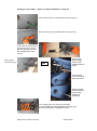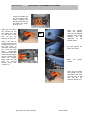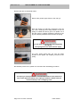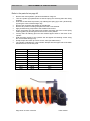
1
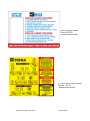
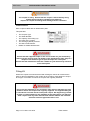
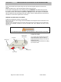
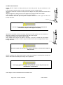
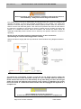
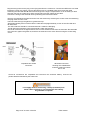
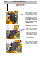
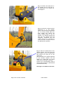
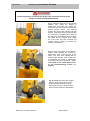
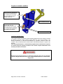
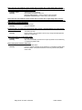
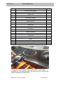
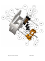
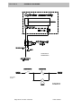
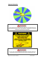
Hill Engineering Limited Unit 6 Carnbane Business Park Newry BT35 6QH Northern Ireland Tel +44(0)28 3025 2555 Fax +44(0)28 3026 4020 www.hillattach.com Installation and User Manual This manual must be kept within the cab of the machine to which the coupler is fitted at all times and be available to all personnel who require this manual. Ensure that the manual is read and understood BEFORE using or performing any work upon the coupler. The information in this document can be subject to change without prior notice and should not be regarded as an undertaking from Hill Engineering Limited. Hill Engineering Limited assumes no responsibility for errors that can appear in this document. Hill Engineering Limited cannot anticipate all dangers and hazards that may arise in the fitting and use of the coupler. Therefore the warnings and safety information included within this document and on any labels provided is not inclusive. Any item or method not specifically recommended by Hill Engineering Limited may be unsafe to yourself or others. It is therefore the responsibility of the customer or his representative to assess the risk and ascertain that it is safe before proceeding. The customer or his representative must also ensure that the safety of the product is not damaged or made unsafe by the operation, maintenance or repair of the coupler. Hill Engineering Limited is not responsible for damage incurred by the use of this document or the quick coupler described in this document. The document, or parts thereof, may not be reproduced or copied without prior permission from Hill Engineering Limited. It may neither be imparted to a third party nor otherwise used without authorisation. Infringement will be subject to action in accordance with applicable laws. Further copies of this document can be obtained from Hill Engineering Limited. ©Copyright Hill Engineering Limited. Document TEF – RO Issued 24-04-15 Hill Engineering Limited Unit 6 Carnbane Business Park Newry County Down BT35 6QH Northern Ireland IMPORTANT INFORMATION The Tefra coupler must only be fitted, used or maintained by personnel who have undertaken the correct and appropriate training and have attained the necessary skill level to safely perform that specific function. Operators must undergo instruction on the correct use of the coupler before using the Tefra coupler. Hill Engineering Limited cannot be held responsible for hazards, damage or injuries caused through the fitting, maintenance, or use of the Tefra coupler by personnel who have not undergone the required training and reached a skill level appropriate for safely carrying out their appointed task. It is the responsibility of the customer to ensure that correct and adequate training has been given to all personnel and that they can perform their appointed tasks in a safe and competent manner. Any personnel working, installing, using or maintaining the Tefra coupler must fully read and understand this manual before commencing. Page 2 of 47 Issue 1O 04/15 Tefra manual HILL ENGINEERING LIMITED TEFRA INFORMATION PREFACE INTRODUCTION 4 SECTION 1 PREPARATION FOR INSTALLATION 7 SECTION 2 INSTALLATION OF THE COUPLER SECTION 2.1 INSTALLATION OF THE COUPLER TO THE EXCAVATOR SECTION 2.2 INSTALLATION OF THE HYDRAULIC HOSES SECTION 2.3 INSTALLATION OF THE SOLENOID VALVE SECTION 2.4 INSTALLATION OF THE CONTROL BOX AND WIRING 8 9 11 13 15 SECTION 3 TESTING THE COUPLER 17 SECTION 4. BUCKET OR ATTACHMENT PICKUP 18 SECTION 5 BUCKET OR ATTACHMENT RELEASE 20 SECTION 6 CONNECTION TEST 21 SECTION 7 USE OF THE COUPLER FOR LIFTING 23 SECTION 8 USE OF THE LIFTING EYE 24 SECTION 9 THE RATED VALUES OF THE COUPLER FOR LIFTING PURPOSES 25 SECTION 10 LIFTING OPERATIONS & LIFTING EQUIPMENT REGULATIONS 27 SECTION 11 SUITABILITY OF ATTACHMENTS 29 SECTION 12 MAINTENANCE 30 SECTION 13 TROUBLESHOOTING 31 SECTION 14 EXTRAORDINARY MAINTENANCE SECTION 14.1 REMOVAL OF THE HYDRAULIC CYLINDER SECTION 14.2 REFITTING OF THE HYDRAULIC CYLINDER SECTION 14.3 REPLACEMENT OF THE COIL SPRING SECTION 14.4 REPLACEMENT OF THE FLAT SPRING SECTION 14.5 REPLACEMENT OF THE PILOT OPERATED CHECK VALVE 33 34 36 37 38 39 SECTION 15 WARRANTY 40 SECTION 16 CONTENTS OF FITTING KIT 42 SECTION 17 SPARE PARTS LIST 43 SECTION 18 STORAGE AND DISPOSAL 45 SECTION 19 SCHEMATIC DIAGRAMS 46 Page 3 of 47 Issue 1O 04/15 Tefra manual PREFACE Introduction and Safety Information General information We take this opportunity to thank you for purchasing a Hill Coupler. The coupler has been tailored to the operator’s needs. The coupler provides a quick and efficient changeover of buckets and attachments. The coupler is a quality engineered, well-designed product capable of providing years of good service, thereby increasing the productivity of your excavator. Please read this manual and any other enclosed documentation fully before commencing installation. This manual should be made available to all persons who may use or maintain the coupler. If any additional information is required then please contact the service department at Hill Engineering Limited or the nearest authorised distributor. Safety All personnel working with the equipment must be well conversed with all of the applicable safety directives/regulations, procedures and precautions. Particular attention should be paid to personal safety while installing, using or maintaining the coupler. Please ensure that all the correct procedures are followed at all times. The user of the coupler is responsible for all precautionary measures concerning personnel working within the excavator risk area. Think Safety, Work Safely, Be Safe In this manual there are parts tagged with one of the following safety warnings. Particular care must be exercised with regard to these statements when performing the work described within that section. DANGER This warning is used where there is a high probability of death or serious injury if the instructions are not followed correctly. ! WARNING This warning is used where there is a possibility of injury to yourself or others if the instructions are not followed correctly. ! This warning is used where there is a possibility of damage to the machine if the instructions are not followed correctly. ! CAUTION Page 4 of 47 Issue 1O 04/15 Tefra manual Revisions The contents of the manual may be subject to revision where necessary. The memo accompanying the revision information should be kept with this manual at all times. Copyright The contents of the manual can be subject to change without prior notice. Hill Engineering Limited is not responsible for damages arising from the use of the manual or the equipment described in the manual. The manual may not be reproduced or otherwise imparted, neither electronic, nor mechanical, without written permission from Hill Engineering Limited. Additional copies of the manual can be obtained from Hill Engineering Limited. ©Copyright 2010. Hill Engineering Limited, Sole right. ! DANGER The value stamped on the lifting eye of the coupler may well exceed the manufacturers rating for the machine at a given radius. The actual capacity the machine will lift at a given radius is given in the manufacturer’s handbook and is not the value stamped on the lifting eye. The load radius may be affected by the fitting of a coupler. This must be taken into account when lifting. The Nett weight of the coupler must be subtracted from the lifting capacity as quoted by the manufacturer i.e. the coupler must be considered as part of the load to be lifted. Always refer to the manufacturer’s specification for the safe load to be lifted at a specific radius. Always use tested and certified lifting chains and shackles. Always use the coupler with the lifting eye pointing downwards when performing any lifting operation. Remove the attachment prior to using the lifting eye. Page 5 of 47 Issue 1O 04/15 Tefra manual SWITCH BOX LABEL Part No STI 20 Location Drivers Cab ATTACH & RELEASE LABEL. Part No. STI 14 Location Drivers Cab. Page 6 of 47 Issue 1O 04/15 Tefra manual SECTION 1 PREPARATION FOR INSTALLATION ! WARNING The coupler is heavy. Ensure that the coupler is lifted carefully using suitable approved lifting equipment and methods. Inspect the coupler and fitting kit for damage before installation. Identification Each coupler is fitted with an identification plate. This plate lists The Coupler Type. The Serial Number. The capacity of the lifting eye. The mass of the coupler. The working hydraulic pressure. The date of manufacture. Details of suitable attachments. ! DANGER Ensure that the supplied coupler is the correct model for your machine by referring to the machine type and model on the identification plate. Only fit a coupler to the machine type as specified upon the serial plate. Ensure that the attachments used are suitable for your machine by reference to the serial plate. Fitting Kit Where the coupler has been delivered with a fitting kit, this kit will contain all the parts for the full installation of the coupler to the machine. Each fitting kit is unique to the type of excavator for which the coupler was originally intended. ! DANGER Do not use the fitting kit for any excavator other than the machine type and model for which the coupler was originally supplied. The supplied fitting kit is intended for use with the Hill Tefra quick coupler. Hill Engineering Limited accepts no responsibility for the suitability of the fitting kit for use with any other coupler from any other manufacturer whether fitted to the intended excavator machine type and model or not. Page 7 of 47 Issue 1O 04/15 Tefra manual SECTION 2 INSTALLATION OF THE COUPLER ! WARNING Installation should only be attempted by skilled and competent personnel who have read fully and understood the information contained within this manual. The coupler installation within the manual is broken down into basic steps, which must be followed. These are as follows: The coupler must be fitted to the end of the excavator’s arm. The hoses must be routed from the coupler to the excavator’s arm. The hoses must be routed from the coupler up the excavator arm and along the boom and down into the engine compartment. The control valve must be installed within the engine compartment affording protection from the elements. The control valve must be connected into the hydraulic pressure and return lines using the T-pieces provided. The switch box must be installed within the excavator cab and the control wiring routed down to the hydraulic valve within the engine compartment, if there is no OEM coupler switch box and wiring. Finally, the function of the coupler must be tested. BEFORE BEGINNING THE INSTALLATION Read all the relevant sections within this manual before beginning the installation. Determine where you will need to mount the hydraulic valve within the main engine compartment close to the excavator’s main pressure pipework. Determine where you will mount the switch box inside the excavator cab, if applicable. Determine the best place to affix the ‘Attach & Release’ safety label as illustrated on page 6 so that it is clearly visible to the excavator operator. Make sure you have the proper fittings needed to tee in to the main hydraulic pressure system and also to the hydraulics return system. Determine the best route for running the hoses on the excavator where they will not contact or interfere with other excavator parts and linkages. Determine the best route for running the wiring harness from the cab to the engine compartment. Pay particular attention to the risk of mechanical damage or chafing. Determine the best location to obtain a connection to the excavator positive and negative electrical terminals. Pay particular attention to the risk of mechanical damage or chafing. Page 8 of 47 Issue 1O 04/15 Tefra manual SECTION 2.1 INSTALLATION OF THE COUPLER TO THE EXCAVATOR ARM Place the excavator and coupler along with any tools and supplies required on flat secure ground. Place the safety lever in the locked position before leaving the cab. If the coupler is shipped with a set of attachment pins REMOVE these attachment pins from the coupler. These attachment pins are NOT case-hardened pins. These pins are designed to be used in the ears of the bucket or attachment. DO NOT connect the coupler to the machine with the attachment pins that shipped with the coupler. Use the original pins that came with the excavator to connect the coupler to the excavator. REMOVE THE EXISTING ATTACHMENT Position the attachment securely on the ground. Remove the nuts from the locking bolts and withdraw the locking bolts from the bushes on the attachment ears. Withdraw both the attachment pins thereby disconnecting the excavator from the attachment. Operate the excavator controls to lift the excavator arm from between the ears of the attachment. ! WARNING The attachment pins are heavy. Get assistance to remove them if necessary Lifting the coupler. Link Hole Dipper Hole (Stick Hole) Lifting Eye The coupler may be lifted using a sling passed through the link pin holes or passed around a dummy pin secured in the link pin holes. Alternatively a shackle fitted in the lifting eye may be used. Front Hook Rear Hook Page 9 of 47 Issue 1O 04/15 Tefra manual FITTING THE COUPLER Ensure that the coupler is resting securely on firm level ground. No pins should be in the coupler. If your machine requires bucket o-rings, install these onto the coupler bosses. Operate the excavator controls to slowly lower the dipper arm (stick) between the ears of the coupler. Align the dipper arm (stick) pin hole to the dipper arm (stick) pin hole of the coupler. Insert the dipper arm (stick) machine pin and any shims if fitted. Use a mallet to drive the pin in to place if required. Ensure the hole aligns with the hole through the bush. Fit dipper pin ! CAUTION Use the original dipper arm (stick) pin that came with the machine to connect the coupler to the dipper arm (stick). Operate the excavator controls to slowly operate the bucket cylinder on the excavator to align the excavator’s pivot link hole with the link-side of the coupler. Insert the link machine pin and any shims if fitted. Use a mallet to drive the pin into place if necessary. A pry bar or similar may be required to help adjust the pivot link in order to align the holes. Ensure the hole aligns with the hole through the bush. Fit link pin ! CAUTION Use the original link pin that came with the machine to connect the coupler to the pivot link. Secure the dipper arm (stick) and link pins in place by inserting the retaining bolts through the holes in the bushes and fitting the locking nuts if applicable. ! CAUTION Thoroughly grease the dipper arm (stick) pin and the link pin as per the manufacturer’s instructions. The coupler is now connected to the excavator arm. Page 10 of 47 Issue 1O 04/15 Tefra manual SECTION 2.2 INSTALLATION OF THE HYDRAULIC HOSES ! WARNING Lock off excavator using plant procedure before commencing work. Before connecting any hoses always flush with clean hydraulic oil to prevent contamination of the hydraulic system. Do not allow hydraulic oil to come into contact with the eyes or skin. Wear safety glasses and gloves at all times. Take steps to minimise oil leakage and prevent spills. Do not pollute drains, waterways, or the environment. Fit the two wire guarded hydraulic hoses to the cylinder and place in a safe position within the coupler body. The BLUE hose fits the A port, the YELLOW hose fits the B port. Start machine and curl coupler into fully crowded position, (i.e. extend crowd cylinder fully). Lower the boom and place the coupler onto the ground in front of the machine. Place the safety lever in the locked position before leaving the cab. Secure a DO NOT OPERATE label to the control console to inform users that the machine is inoperable. Release the hydraulic tank pressure by operating the release valve on the hydraulic tank if applicable. ! DANGER The hydraulic system MUST be depressurised before commencing installation, safety equipment must be worn while carrying out this operation ! WARNING Before proceeding with any welding, battery leads must be removed from the battery. Always check with the excavator dealer to take appropriate measures when welding on the machine. Welding may cause fires. Always remove combustible materials from the vicinity. Protect all hoses and wiring from weld spatter. Keep a fire extinguisher available in case of fire. Always use the correct personal protective equipment. Page 11 of 47 Issue 1O 04/15 Tefra manual Reverse Hose Kit Position the manifold close to the bottom of the dipper stick. This dimension is approximately 60 mm for a 3T series machine up to 300 mm on the largest machines. This is only a guide and may vary between machines. It is recommended that the block is temporarily fastened in position and the coupler moved through its full range of travel with the pipes connected to optimise the block position). In this position, the spring-guarded hoses should be in a neat position with minimal slack around bottom of dipper arm (stick) when in the fully crowded position. Once the optimum position for the block is determined, weld only in the areas shown below. Attachment of clamps The clamps are supplied with a bottom weld on plate. The hose clamps may be welded in position by a qualified person using the correct materials and procedures. Before welding the bottom plate should be unbolted from the clamp assembly. The plate should be allowed to cool following welding before refitting the clamp assembly. Main Hoses The hose kit will consist of two blue hoses and two yellow hoses (marked with coloured tape at each end). Connect the shorter yellow hose to port “B” of the manifold block and the shorter blue hose to port “A” of the manifold block. Secure the hoses to the dipper arm using the hose clamps. The remaining length of these 2 hoses should then be fastened to the existing hydraulic pipes that run along the boom using the cable ties provided. Attach the two longest hydraulic pipes and cable tie to existing hydraulic pipes that run down the boom. Route the hoses into the engine bay ensuring they cannot become trapped or chaffed by movement of the boom or vibration of the machine. Page 12 of 47 Issue 1O 04/15 Tefra manual SECTION 2.3 INSTALLATION OF THE SOLENOID VALVE ! WARNING Lock off excavator using plant procedure before commencing work. Before connecting any hoses always flush with clean hydraulic oil to prevent contamination of the hydraulic system. Do not allow hydraulic oil to come into contact with the eyes or skin. Wear safety glasses and gloves at all times. The solenoid valve will arrive with all 4 ports bare; the following fittings should be connected: Port P fit 3/8” BSP male with bonded seal to ¼” BSP male. Port T fit 3/8” BSP male with bonded seal to 3/8” BSP male. Port A fit 3/8” BSP male with bonded seal to ¼” BSP male. Port B fit 3/8” BSP male with bonded seal to 7/16” JIC male. In order for the coupler and smart valve to function correctly a non-return valve must be fitted in the P (Red) line to the solenoid valve. Screw the non-return valve onto the ¼” BSP male on the “P” port using a dowty seal, the arrow on the body of the non-return valve MUST face towards the solenoid valve. Screw the supplied ¼ BSP x ¼ BSP M-M fitting into the INLET port of the non-return valve using a dowty seal. Mount the solenoid valve in a safe and dry position close to the main hydraulic pump by drilling and tapping two holes in a suitable position and fitting two bolts through the mounting holes provided within the valve body. Alternatively if the kit contains a mounting plate this can be used to match bolts available in the engine bay. ! WARNING Wear eye protection when drilling and tapping. Beware of sharp edges and hot metal particles. Ensure loose clothing or hair cannot become entangled If mains powered equipment is used use suitable precautions to avoid the danger of electrocution Locate a return pipe leading to the hydraulic oil tank. Connect into this line using the T-piece provided. Connect the solenoid valve port T to this T-piece using the GREEN hose for the return of hydraulic oil to the tank Connect the hoses coming from the coupler to the solenoid valve, the blue hose is connected to Port A, the yellow hose to Port B. Port P on the solenoid valve must be connected into the MAIN PUMP PRESSURE between the MAIN PUMP and the valve bank for the excavator cylinders using the RED hose and Tpiece provided. On some models of excavator, the connection to the main pump pressure can be achieved by removing the test port on the main pump and replacing it by using a suitable fitting. ! DANGER The coupler requires full machine pressure to operate Do not use anything other than full machine pressure. Page 13 of 47 Issue 1O 04/15 Tefra manual A Summary of the connections including diagram and picture are shown below Pipe from pump to port P on valve – ¼” BSP colour RED. Pipe from tank return to port T on valve – 3/8” BSP colour GREEN. Pipe from port A to coupler – ¼” BSP colour BLUE. Pipe from port B to coupler – 7/16” JIC colour YELLOW. ! WARNING Reversal of the A and B connections to the coupler will result in incorrect operation of the coupler. Page 14 of 47 Issue 1O 04/15 Tefra manual SECTION 2.4 INSTALLATION OF THE CONTROL BOX AND WIRING ! WARNING Before proceeding with the installation, the battery leads must be removed from the battery. Always disconnect the ground lead first. Find a safe place in the cab to install switch and buzzer/control box, where it is visible to the operator and where it will not be contacted accidentally by the operator. The control box should be mounted using the double-sided adhesive pads provided. Clean the area first to ensure it is free from dust and grease. Then remove the protective film from the outer side of the pad that is provided on the bottom of the box. Position the box carefully and press into position on a suitable flat surface within the excavator cab. Ensure the switch cannot be contacted accidentally and the buzzer can be heard by the operator whilst the machine is operating. NOTE. The pad provided provides a permanent fixture. It does not allow for repositioning so select the mounting position carefully. Always fuse the live supply with a 5 Amp maximum fuse and follow wiring diagram illustrated below. The switch box incorporates a power on self test for the buzzer function. When the ignition is turned on then the buzzer sounds for 3 to 5 seconds while its function is tested. Should this test fail or a fault develop at any time during use then the red light within the switch will illuminate and unlocking of the coupler is inhibited by the control box. In the event of a switch box failure the box must be unplugged and replaced as a complete unit. ! CAUTION Do not attempt to service the control box. In case of a fault the control box must be replaced as a complete unit Page 15 of 47 Issue 1O 04/15 Tefra manual Plug the wiring loom into the plug on the flying lead from the control box. Connect the RED wire to a fused (maximum 5 amp) live supply. Connect the BLACK wire to a suitable earth point. Route the cable containing the YELLOW and BLACK wires through to the engine compartment. If it is necessary to drill a hole then remove any sharp burrs and fit a grommet to prevent chafing of the cable. Connect the wiring to the solenoid valve by following the instructions below. Remove and dismantle the DIN Connector from the solenoid by removing the centre screw and extracting the plug insert from the cover. Pass the cable through the gland nut, glands and cap. Strip approximately 25 mm of the multicore cable and strip approximately 10 mm of the YELLOW and BLACK cores. The YELLOW wire should be connected terminal 1 within the DIN plug. The BLACK wire should be connected terminal 2 within the DIN plug. Ensure all connections are tight and there are no loose strands of wire from the terminals. Re-assemble the connector, tighten the gland nut, and fit to the solenoid on the valve. Secure using the centre fixing screw. 1-Yellow 2-Black Exploded view of DIN Connector Wired DIN connector showing YELLOW/BLACK multicore cable from switch box in cab Check all connections are completed and reconnect the excavator battery. Connect the positive lead first followed by the earth lead. ! WARNING Live supply must be fused using a 5-amp (maximum) fuse. Route cables carefully to prevent damage and chafing. Fit grommets if required. Page 16 of 47 Issue 1O 04/15 Tefra manual SECTION 3 1. TESTING THE COUPLER Check Buzzer and Warning lamp within control box for correct operation. This can be done as follows: Turn on the ignition and the buzzer should sound for 3 – 5 seconds as a self test. Operate the Bucket Release switch and check the buzzer sounds Return the Bucket Release switch to the off position. NOTE. If either the warning lamp within the switch illuminates or the buzzer fails to function contact Hill Engineering Service for advice and do not use the coupler. 2. Start the excavator. 3. Increase the engine RPM to no more than 50% of the maximum. 4. Crowd the coupler fully i.e. fully extend the crowd cylinder. 5. Visually check from a safe distance that the hook is forward i.e. the cylinder is fully extended rear hook fully forward and the front hook is in the down (closed) position. 6. Operate Bucket Release to withdraw hook. Keep the hydraulic system under pressure by continuing to extend the crowd cylinder. Check that front hook also moves into the coupler, i.e. clear of the front pin aperture. 7. Open and close the coupler several times to assist with bleeding air from the system by operating the Bucket Release switch. 8. Allow time for the hooks to open and close fully before reversing switch position. 9. Turn off the excavator and check all hydraulic fittings on the coupler system and rectify any hydraulic oil leaks. 10. Finally, stick the warning sticker to a suitable surface within the drivers cab. (See Page 6) 11. To apply remove the backing paper and checking that the surface is clean and dry, apply using firm pressure. ! WARNING Hydraulic fluid under pressure can penetrate the skin. Do not test for leaks with bare hands. Wear overalls, gloves and a full-face shield. Use containers and absorbent materials to contain any leakage. Page 17 of 47 Issue 1O 04/15 Tefra manual SECTION 4 BUCKET OR ATTACHMENT PICK UP ! DANGER Ensure all persons are outside the danger area and remain outside of the danger area while changing attachments. Fig. 1: With the bucket release switch in the off position the front hook will be clearly visible from the operator’s position inside the cab. Ensure the area is clear from personnel and obstructions. When releasing or picking up an attachment ensure that the machine RPM is no more than 50% of the maximum. Release the crowd lever before operating the switch. Fig. 2: Move the dipper arm into the vertical position and fully crowd the coupler. Release the crowd lever. Operate the bucket release switch. The warning buzzer will sound and warning light will display. Pressurise the link crowd control for 5 seconds to withdraw the front and rear hooks. Ensure the coupler is crowded BEFORE operating the bucket release switch otherwise the Hill Smart Valve will prevent the coupler opening. If this occurs turn off the switch and start from the beginning. Fig. 3: When the rear hook has withdrawn the front hook will rotate into the coupler body. When the front hook has fully retracted the coupler will be ready to pick up the bucket or attachment. Page 18 of 47 Issue 1O 04/15 Tefra manual Fig. 4: Position the fixed jaw of the coupler over the front pin of the attachment to be picked up and engage it. Fig. 5: Crowd the coupler until the attachment is in the position shown. Check that the front bucket pin is correctly located within the front coupler jaw. Return the bucket release switch to the off position. The warning buzzer will stop and the warning light will extinguish. Pressurise the link crowd control for 5 seconds to move the hooks forward and lock the attachment in position. Fig. 6: Move the attachment to the position shown. The front hook will have rotated out of the coupler body and around the front pin of the attachment. The front hook is the visible indication to the machine operator that the safety is in effect and it is clearly visible from the operator’s position. Perform the recommended tests to ensure that the bucket or attachments are attached securely. See Page 21 for details of the tests Page 19 of 47 Issue 1O 04/15 Tefra manual SECTION 5 BUCKET OR ATTACHMENT RELEASE ! DANGER Ensure all persons are outside the danger area and remain outside of the danger area while changing attachments. Fig. 7: With the dipper arm in the vertical position fully crowd the bucket or attachment. Take care not to crash the bucket into the cab or tracks. Operate the bucket release switch. The warning buzzer will sound and warning light will display. Pressurise the link crowd control for 5 seconds to withdraw the hooks. As the rear hook is withdrawn the front hook will rotate into the coupler body. When the front hook has fully retracted the coupler will be ready to release the bucket or attachment. Fig. 8: Move the coupler to the position shown while keeping the bucket or attachment close to the ground at all times. The front hook should not be visible to the operator. Find a safe area to discharge the bucket or attachment well away from other personnel. If the front hook is still visible please refer to the troubleshooting section on page 31. Fig. 9: Rotate the rear of the coupler until it is clear of the rear pin of the bucket and then slide the coupler clear of the front pin. Lift the coupler away from the bracket or attachment. Page 20 of 47 Issue 1O 04/15 Tefra manual SECTION 6 CONNECTION TEST ! DANGER Before commencing work with a changed attachment, always perform the connection test to ensure coupling has been successful. Always perform connection tests away from any personnel. COUPLER CONNECTION TEST Test the connection to the attachment by completely crowding the coupler inward and then uncurling fully. Perform this test two or three times. Watch the coupled attachment carefully for any sign of instability or unusual movement. If the connection to the attachment appears correct having performed the above test then place the attachment in contact with the ground and try to force the coupler away from the attachment. Make use of the weight of the excavator when performing this final test. ! DANGER If the attachment fails any of the above tests then release the attachment following the correct procedure and repeat the pick-up procedure. Never swing coupled attachments over the heads of personnel. Never allow personnel to work under the coupled attachment. This is true whether the excavator is working or not. The front orange hook should be visible at the front of the coupler from the cab in the locked condition and fully enclose the front pin. Page 21 of 47 Issue 1O 04/15 Tefra manual Coupler in locked condition Front hook fully closed and enclosing front attachment pin retaining the pin within the front aperture of the coupler as shown. Front attachment pin Rear hook forward and in contact with the rear attachment pin forcing the rear attachment pin against the coupler body within the rear aperture as shown. Rear attachment pin Locking mechanism The coupler locking mechanism is automatically applied when the coupler is closed by switching off the coupler release switch within the cab of the machine. The locking mechanism is removed automatically by hydraulic pressure when the coupler is fully crowded and the release switch operated allowing the coupler to be opened. The locking mechanism is automatically applied and released and requires no action from the operator outside of the normal coupler attachment and release procedure to function. ! DANGER Before turning off the machine or leaving the machine idling for an extended period, always lower the boom so the coupled attachment is in contact with the ground. Page 22 of 47 Issue 1O 04/15 Tefra manual SECTION 7 USE OF THE COUPLER FOR LIFTING ! DANGER Not all excavators are equipped for lifting. Attention should be paid to the manufacturers instructions as supplied with the machine. Hill Engineering accepts no liability for lifting operations performed on machines not equipped for lifting. The presence of a lifting eye upon the coupler does not mean that the machine is approved for lifting operations. Never use a coupler to transport or lift persons if the machine is not designed and equipped for this purpose The Tefra coupler is supplied as a lifting accessory and under the Lifting Operations and Lifting Equipment Regulations (LOLER) regulations must be thoroughly inspected by a competent person at intervals not exceeding six months. If the coupler is removed from the machine for any reason then it must undergo a full examination, once fitted to the excavator, before being put back into service to comply with the LOLER regulations. Every coupler leaves the factory with a full CE certificate of conformity and a certificate as to the safe working load of the coupler. This CE certificate of conformity is valid for LOLER purposes for six months from the date of first fitting the coupler to the excavator provided the coupler is first fitted within twelve months of the date of manufacture. If the coupler is used with a dedicated lifting attachment, the maximum lifting capacity is the same as that marked on the lifting eye. Any moment loads seen by the coupler must be taken into account when calculating the lifting capacity. Page 23 of 47 Issue 1O 04/15 Tefra manual SECTION 8 USE OF THE LIFTING EYE The working load limit of a coupler is stamped into the rear plate of the coupler close to the lifting eye. This working load limit applies to a load applied directly to the lifting eye or any total load applied to the coupler through the use of a lifting attachment. The lifting eye is not designed to have loads exerted upon it in any other direction and this must be avoided. Chains etc. attached to the lifting eye and used for lifting must be attached via the use of a certified shackle. ! DANGER Never exceed the rated capacity of the lifting eye. Always remove attachments before using the lifting eye. Use only certified and tested lifting accessories. Remove any attachment before using the lifting eye. Always fit the correct sized shackle to the hole in the lifting eye for attachment of the chain or sling. Always place the coupler flat on the floor and turn off the excavator when fitting or removing chains and slings. The lifting eye is intended for straight lifts only as indicated. Do not use the lifting eye for pulling at an angle. Remove any attachments prior to using the lifting eye for lifting. Always allow for the weight of the coupler and the effect it may have on the load radius when calculating the lifting capacity from the machine manufacturer’s specification chart. ! DANGER Never use any other part of the coupler for lifting. Never use any part of the coupler for pushing or prying. Only use tested and certified chains or slings for lifting. Do not swing suspended loads over the heads of other personnel. The use of a coupler for lifting may affect the load radius. Remember to reduce the lifting capacity by the mass of the coupler. The WLL (working load limit) is the maximum load the lifting eye can lift. The WLL may exceed the rated capacity of the machine at a specific radius. Always use the lower of the manufacturers figure (reduced by the weight of the coupler) or the WLL of the lifting eye when calculating the lifting capacity. Page 24 of 47 Issue 1O 04/15 Tefra manual SECTION 9 THE RATED VALUES OF THE COUPLER FOR LIFTING PURPOSES When an attachment is used for lifting it must be ensured that the attachment pins within the head of the attachment are the correct size for the coupler and that the attachment pin centre distances (pin spread) within the head of the attachment are within the correct pick up range for the coupler. Only attachments with double pin heads must be used, Single pin heads are NOT allowed under any circumstances. Excavator mounted vibratory (EMV) equipment or similar require a suitable bracket, so as equipment can be used as originally intended by the manufacturer. Coupler capacity guide chart These values may be in excess of the machine capacity. Refer to manufacturers lifting chart for the machine capacity. Machine size (typical) 3 tonne 5 tonne 7 tonne 13 tonne 16/20 tonne 25 tonne 30 tonne + Attachment pin diameter (mm) (bottom of coupler pick up) 35 40 38 40 45 50 45 50 60 60 65 70 80 90 100 110 120 120+ Minimum pin centres (mm) 162 162 216 216 218 221 279 281 279 345 345 386 386 455 517 517 517 Maximum pin centres (mm) 217 217 272 272 270 267 356 353 356 435 435 510 510 572 650 650 650 Front Pin Capture Rated Capacity Rear Pin Capture Rated Capacity 1 tonne 1 tonne 2 tonne 2 tonne 2 tonne 2 tonne 2.5 tonne 2.5 tonne 2.5 tonne 4 tonne 4 tonne 6 tonne 6 tonne 8.5 tonne 10.5 tonne 10.5 tonne 13.5 tonne 1 tonne 1 tonne 2 tonne 2 tonne 2 tonne 2 tonne 2.5 tonne 2.5 tonne 2.5 tonne 4 tonne 4 tonne 6 tonne 6 tonne 8.5 tonne 10.5 tonne 10.5 tonne 13.5 tonne Total Capacity of Lift using Front and Rear Pin Captures 2 tonne 2 tonne 4 tonne 4 tonne 4 tonne 4 tonne 5 tonne 5 tonne 5 tonne 8 tonne 8 tonne 12 tonne 12 tonne 17 tonne 21 tonne 21 tonne 27 tonne Lifting Eye Rated Capacity Coupler proof load 2 tonne 2 tonne 4 tonne 4 tonne 4 tonne 4 tonne 5 tonne 5 tonne 5 tonne 8 tonne 8 tonne 12 tonne 12 tonne 17 tonne 21 tonne 21 tonne 21 tonne 4 tonne 4 tonne 8 tonne 8 tonne 8 tonne 8 tonne 10 tonne 10 tonne 10 tonne 16 tonne 16 tonne 24 tonne 24 tonne 34 tonne 42 tonne 42 tonne 42 tonne Note: The above chart is for reference only. To determine the correct values for your coupler model please refer to either the certificate of conformity as delivered with the coupler or the value stamped on the front of the coupler adjacent to the lifting eye. The values quoted are for central loads with the coupler in the horizontal position. When using the bottom of the coupler for lifting care must be exercised to consider any moment or offset loading which may be seen by the coupler. ! DANGER Never overload the coupler or machine. Overloading may result in permanent damage and personal injury. The use of a coupler for lifting may affect the load radius. Remember to reduce the lifting capacity by the mass of the coupler. Page 25 of 47 Issue 1O 04/15 Tefra manual Example of a lifting attachment Excavator mounted vibratory bracket Double Pin Head Suitable for use ! Single Pin Head DO NOT USE DANGER Single pin attachment heads must not be used under any circumstances. Page 26 of 47 Issue 1O 04/15 Tefra manual SECTION 10 LIFTING OPERATIONS AND LIFTING EQUIPMENT REGULATIONS STATUTORY INSPECTION IN ACCORDANCE WITH LIFTING OPERATIONS AND LIFTING EQUIPMENT REGULATIONS 1998 The coupler requires inspection at six monthly intervals to comply with the LOLER requirements Guide line notes to be used for the LOLER inspection. 1. Coupler Body. 1.1. 1.2. 1.3. 1.4. Body must be free from any major damage or distortion. Coupler body must be sound and free from distress or fractures. Lifting eye must be free from damage and excessive wear. Front aperture or gub must be free from damage distortion or excessive wear. 1.5. Check for wear in or cracking from the machine attachment bores. 1.6. Check for wear in or cracking from the hook pivot holes. 1.7. Check for wear in or cracking from the cylinder rear mounting holes. Pay particular attention to the coupler front plate, rear plate and lifting eye. 2. Rear hook 2.1. 2.2. 2.3. 2.4. 2.5. 2.6. Hook must be free from any major damage or distortion. All must be sound and free from fractures. Check for wear in or fractures from the hook pivot bore. Check for wear in or fractures from the cylinder pivot bore. Check for excessive wear on the pin clamping face. Check for wear in mounting holes and pins. 3. Hydraulic cylinder 3.1. Check for oil leaks. 3.2. Check for full range of movement. 3.3. Check for wear in mounting holes and pins. 4. Pivot bars 4.1. Check for wear. 4.2. Check circlips are present and secure. 5. Switch box 5.1. 5.2. 5.3. 5.4. 5.5. Check for correct operation of self test at ignition on if applicable. Check for correct operation in use. Check for lock function if applicable. Check for illumination of switch if applicable. Check buzzer operation. 6. Wiring 6.1. Check for damage/chafing. Page 27 of 47 Issue 1O 04/15 Tefra manual 7. Hydraulic system 7.1. 7.2. 7.3. 7.4. 7.5. Check for oil leaks. Check hoses for damage/chafing. Check for corrosion of hose fittings. Check for security of solenoid valve. Check for correct pressures in the coupler supply lines in the two valve states :7.5.1. Valve de-energised machine pressure in A-line, minimal pressure in the B-line. 7.5.2. Valve energised machine pressure in B-line, minimal pressure in the A-line 8. Instruction/safety labels 8.1. Check for presence. 8.2. Check for legibility. 9. Creep test. 9.1. Position a fully locked attachment just clear of the floor with the coupler in the attitude shown. Observe normal safety procedures when approaching coupler. Measure the position of the attachment relative to the coupler or measure the main cylinder ram extension if possible. Turn off the machine and leave for 30 minutes. After this time approach the coupler with caution and recheck the measurement between the datum points. If the measurement remains the same the coupler has passed the creep test. Any movement of the attachment or change in the main cylinder ram extension signifies a failure. ! DANGER The attachment may become loose in the event of a creep test failure. Exercise caution when approaching and examining the attachment. Page 28 of 47 Issue 1O 04/15 Tefra manual SECTION 11 SUITABILITY OF ATTACHMENTS Most excavator attachments with a two pin connection system are suitable for use with Tefra coupler. These include: Buckets – Trenching, Ditching, Grading, Rock, Riddle etc.* Clamshell buckets with two pin attachments* Rippers – all types* Compactors – Wheel and plate* Rakes, Breakers – See Note Hydraulic grabs and grapples with two pin attachment plates Hydraulic Shears with two pin attachment plates Flail Mowers, kerb lifters. *Note. Where stiff arm attachments are used then the stiff arm must be pivoted on the main dipper (stick) pin of the machine, NOT the front pin within the jaw of the attachment. Hydraulic thumbs or similar with pressure reduction/relief valves incorporated may be used if correctly set. If a hammer or breaker is to be used for an extended period then it is recommended that the coupler is removed and the hammer mounted directly to the machine. The hammer should ALWAYS be used in the vertical position and NEVER use the hammer as a lever. The coupler frame and parts should be inspected frequently. If in doubt please call Hill Engineering Limited or your authorised dealer/supplier for advice. Page 29 of 47 Issue 1O 04/15 Tefra manual SECTION 12 MAINTENANCE ! DANGER Never neglect the daily maintenance. Failure to perform the daily maintenance correctly could lead to dangerous undetected faults that could result in the unexpected disengagement of the attachment during normal working. Daily 1. Always ensure that Health and Safety regulations are followed. 2. Grease the rear hook pivot pin, front hook pivot pin, spring pivot pin, and both hydraulic cylinder pivot pins as necessary with general purpose grease. 3. Check the coupler, coupler cylinder and hydraulic pipes for damage and replace or repair as necessary. 4. Check the coupler for any dirt or debris and clean regularly. 5. Check the coil spring fitted to the cylinder for integrity and damage. 6. Check all safety labels in the cab interior are in place and legible. Replacement labels are available from Hill Engineering Service Department. 7. Check Buzzer and Warning lamp within control box for correct operation. This can be done as follows: 1 Operate the Bucket Release switch and check the buzzer sounds and the lamp illuminates. 2 Return the Bucket Release switch to the off position. 8. Check that the pin circlips are all present and located in the pin grooves provided. 9. Check that the flat spring bolts are tight (see Section 14.4 for torque settings). 10. The orange hooks should be repainted when necessary and must be visible to the machine operator from a seated position within the cab. Weekly Thoroughly clean the coupler and closely inspect all the coupler body for fatigue fractures. If any distressed welds are detected on a fabricated coupler then they must be repaired immediately to prevent propagation of the damage. Check the Bucket pins for wear and replace if necessary. Check the hook for wear in the bucket pin area this can be built up by welding on certain coupler models. Contact Hill Engineering for advice before attempting repair. Failure to comply with the Daily and Weekly Maintenance listed above or any attempt of an unauthorised repair will invalidate the warranty. Page 30 of 47 Issue 1O 04/15 Tefra manual SECTION 13 TROUBLESHOOTING Hydraulic leaks: Probable cause: Remedy: Loose or damaged hoses. Check, tighten/replace as necessary. No buzzer when operating switch box: Probable cause: Remedy: No power, check supply fuse. Check supply fuse – see section 2.4. Red light illuminates on switch box: Probable cause: Remedy: Switch box faulty. Replace switch box – see section 2.4 Rear hook does not withdraw and front hook does not rotate into coupler body when switch is operated (buzzer on): Probable cause: Remedy: Machine RPM too high and/or incorrect coupler position. Reduce RPM - return switch to the off position, fully crowd coupler, operate switch. Rear hook withdraws then closes when machine rpm falls (buzzer on): Probable cause: Remedy: Check valve not working in the P line of the solenoid valve. Fit or replace check valve. Rear hook does not withdraw and front hook does not rotate into coupler body when switch is operated (buzzer on, coupler fully crowded) - Hydraulic pressure can be seen to swop from one spring hose to the other when the switch is operated: Probable cause: 1. Air in hydraulic system. 2. Cylinder valve stuck. 3. Inlet strainers blocked. Remedy: 1. Bleed hydraulic system. 2. Crowd coupler and isolate the machine. Remove the smart valve cap and ball. In extreme cases it may be necessary to give the block a sharp tap to dislodge the ball. Clean ball and refit. Bleed the system. 3. Remove hoses from cylinder block. Inspect ports internally and clean out any debris if necessary. Smart Valve Cap Take care not to lose steel ball when removing. Remove cap with coupler in the crowded position so the ball enters the recess in the cap. Strainers within inlet ports Remove hoses from cylinder block. Inspect ports internally and clean out any debris if necessary. ! DANGER Always place the attachment securely on a flat level surface that it cannot become unintentionally detached before approaching/examining the coupler. Isolate and lock off machine and controls. Troubleshooting procedures should only be performed by a competent person. Call Hill Engineering Service or an appointed agent for advice/assistance if necessary. The rear hook is closed by a powerful spring. Be aware that the rear hook will close if hydraulic power is removed from the coupler. Keep hands clear of moving parts when hydraulic power is removed from the coupler by disconnecting pipes or turning off the machine. The check valve will keep oil supplied to the coupler under pressure. To discharge this pressure, operate the coupler release switch a few times with the ignition on but engine off. Page 31 of 47 Issue 1O 04/15 Tefra manual Rear hook does not withdraw and front hook does not rotate into coupler body when switch is operated (buzzer on, coupler fully crowded) - Hydraulic pressure does not swop from one spring hose to the other when the switch is operated: Probable cause: Remedy: Solenoid valve not operating Check wiring to solenoid valve coil. Power at solenoid coil – replace solenoid valve assembly. No power at solenoid coil – check wiring and switchbox. Rear hook does not withdraw and front hook does not rotate into coupler body when switch is operated (coupler fully crowded) - Hydraulic pressure does not swop from one spring hose to the other when the switch is operated Red Indicator in switch illuminates: Probable cause: Remedy: Switch box fault. Replace switchbox. Front hook does not rotate into coupler body when switch is operated (buzzer on) hook retracts, coupler fully crowded: Probable cause: Remedy: Jammed front hook. Return switch to the off position. Remove any foreign materials jammed within the coupler body. Attachment rattles on coupler when used: Probable cause: Remedy: Hydraulic failure. Stop work immediately and have the coupler hydraulic circuit checked by a competent hydraulic fitter. Rear hook/cylinder retracts under load: Probable cause: Remedy: Check valve/seal failure. Have the coupler hydraulic circuit checked by a competent hydraulic fitter. Ensure cylinder is de-pressurised before removing the internal cylinder check valve. Page 32 of 47 Issue 1O 04/15 Tefra manual SECTION 14 EXTRAORDINARY MAINTENANCE ! WARNING Work within this section should only be attempted by skilled and competent personnel who have read fully and understood the information contained within this manual. ! CAUTION Contamination entering the hydraulic system of the excavator through the disconnected pipes may do serious damage to the hydraulic system. Take steps to minimise oil leakage and prevent spills. Do not pollute drains or waterways, or the environment. Replacement of hoses ! WARNING Take care to prevent oil spills. Hydraulic fluid under pressure can penetrate the skin. Wear overalls, gloves and a full-face shield. Use containers and absorbent materials to contain any leakage. Beware of residual hydraulic pressure. Do not re-use hose fittings. Ensure hoses used comply with current legislation and are rated for the pressure of the machine. Uncouple any attachment if possible. Place the coupler/attachment on firm level ground using the excavator controls. Turn off the excavator and place the safety lever into the locked position. Lock out the excavator according to plant rules. Release the hydraulic tank pressure by operating the release valve on the hydraulic tank if applicable. Clean the area around the hydraulic pipe to be disconnected with a clean rag. Unscrew the hose connections catching any escaping oil in a suitable container. Replace the damaged hose with an identical hose. Tighten firmly. Start machine and check for leaks. Retighten if necessary. Dispose of old hose and oil conforming to current local/national bye laws/legislation on disposal. Page 33 of 47 Issue 1O 04/15 Tefra manual SECTION 14.1 REMOVAL OF THE HYDRAULIC CYLINDER ! WARNING Take care to prevent oil spills. Hydraulic fluid under pressure can penetrate the skin. Wear overalls, gloves and a full-face shield. Use containers and absorbent materials to contain any leakage. Beware of residual hydraulic pressure Uncouple any attachment. Place the coupler on firm level ground using the excavator controls. Ensure the cylinder is fully extended. Turn off the excavator and place the safety lever into the locked position. Lock out the excavator according to plant rules. Release the hydraulic tank pressure by operating the release valve on the hydraulic tank if applicable. Remove the nuts from the bolts securing the dipper arm (stick) and link pins in place. Remove the bolts securing the dipper arm (stick) and link pins in place. Remove the link machine pin and any shims if fitted. Use a mallet to drive the pin out if necessary. Remove the dipper arm (stick) machine pin and any shims if fitted. Use a mallet to drive the pin out if necessary Clean the area around the cylinder hydraulic pipes with a clean rag. ! CAUTION Contamination entering the hydraulic system of the excavator through the disconnected pipes may do serious damage to the hydraulic system. Disconnect and cap the hydraulic pipes. Suitable caps can be obtained via your dealer or distributor. Using the excavator controls remove the dipper arm (stick) and link from the coupler. Turn off the excavator and place the safety lever into the locked position. Lock out the excavator according to plant rules. ! WARNING The attachment pins are heavy. Get assistance to remove them if necessary Page 34 of 47 Issue 1O 04/15 Tefra manual Working on the coupler: - (Refer to coupler breakdown on page 44) Remove the circlip (11) retaining the ram pivot pin (7) Remove the circlip (10) retaining the ram rod pin (9). Use the correct dummy pin, for the size of coupler, drive out the ram rod pin (9) so that the dummy pin is flush with outside faces of the rod eye. Drive out the ram pivot pin (7) OR Remove the grease nipple from the ram retaining sleeves (16A). Unscrew and remove retaining Allen cap screw. Extract cylinder retaining sleeves using a slide hammer or similar tool. The cylinder (2) is now free to be removed. It may be lifted clear while guiding the flat spring (5) from the slot within the spring pivot pin (7) Page 35 of 47 Issue 1O 04/15 Tefra manual SECTION 14.2 REFITTING OF THE HYDRAULIC CYLINDER Lower the cylinder (2) into the coupler body whilst engaging the flat spring (5) into the slot within the spring pivot pin (17). Align the hole within the cylinder rod eye hole within rear hook (4) and drive in the ram rod pin (9). Replace circlips (10). Align the cylinder within the aperture and refit the retaining sleeves (16A) paying attention to the alignment of the grease nipple. OR Using a pry bar as shown apply pressure centrally to the top of the ram block to pretension flat spring (5). Force the ram block downwards until the pivot pin hole within the block aligns with the mating hole within the coupler body. Refit the ram pivot pin (16).and secure using new circlips (11). Fit and tighten the Allen cap screws Refit the nipples # Page 36 of 47 Issue 1O 04/15 grease Align the hole within the cylinder rod eye hole within rear hook (4) and drive in the ram rod pin (9). Replace circlips (10). Tefra manual SECTION 14.3 REPLACEMENT OF THE COIL SPRING Remove the ram as described earlier. Remove the grease nipple from the ram rod eye. Drive the dummy pin half way through the ram rod eye. Use a small pry bar to keep tension on the coil spring to enable the dummy pin to be pulled out of the ram rod eye. Carefully release the tension on the pry bar until the preload is removed from the spring. ! DANGER Do not allow yourself to become trapped by the spring. The spring force can cause serious injury. The inner spring guide tube can now be pulled forward off the piston rod enabling removal of the spring. Re-assembly of the main cylinder is a reversal of the dismantling procedure. ! . DANGER The spring is under pretension. Uncontrolled release of the pretension may cause rapid movement of the spring or retainer. Always exercise caution and keep clear of trapping areas. Page 37 of 47 Issue 1O 04/15 Tefra manual SECTION 14.4 REPLACEMENT OF THE FLAT SPRING Refer to the parts list on page 43 Remove the main hydraulic cylinder as detailed on Page 34. Turn the cylinder (2) upside down so that the spring and securing bolts are facing upwards. Undo the socket head cap screws (14) retaining the spring (5) to the cylinder body (2) using the correct sized hexagon key. Remove the old spring and helpers (5) and discard. Remove any traces of locking compound from the screw threads. Apply thread locking compound to the threads of all screws. Fit the new spring (5) and helpers into position and align the holes in the spring retaining plate (15) ensuring the bevel is in the correct position. Loosely start all retaining pins into their relative tapped holes in the base of the cylinder. Hold the spring square to the cylinder axis and tighten all retaining screws using the correct sized hexagon key. Finally torque all screws up to their correct value (see table below). The cylinder is identified by a part number stamped into the upper side of the block beside the hose connection ports. Cylinder size Screw size Torque wrench setting (Nm) 3T M8 40 5T M10 77 7T M12 135 13T M14 215 20T M16 325 25T M16 325 35T M20 640 65T M16 325 100T M16 325 Page 38 of 47 Issue 1O 04/15 Tefra manual SECTION 14.5 REPLACEMENT OF THE PILOT OPERATED CHECK VALVE ! DANGER The pilot operated check valve locks hydraulic pressure into the cylinder. Always relieve the hydraulic pressure within the cylinder by following the procedure described below. Failure to follow the procedure will result in damage to the check valve and may result in injury. Always wear skin and eye protection when working on hydraulics The pilot operated check valve is a very reliable unit and it is unlikely that repair or replacement will be required during the life of the coupler. Remove any attachment. Crowd and fully retract/open the coupler. Turn off the machine with the coupler in the retracted/open position. Isolate and lock off machine. Using a 22 mm socket unscrew the check valve from the rear of the cylinder block. Inspect all seals and replace if suspect. Note. If replacing seals ALL seals must be replaced. When fitting replacement seals take great care not to overstretch the seals as this will irreparably damage the seals and the check valve may not function as intended. Replacement is simply achieved by carefully inserting the body of the check valve into the cavity and tightening to the correct torque of 40 Nm. ! WARNING Take care to prevent oil spills. Hydraulic fluid under pressure can penetrate the skin. Wear overalls, gloves and a full-face shield. Use containers and absorbent materials to contain any leakage. Beware of residual hydraulic pressure ! CAUTION Always oil the check valve seals before reassembling into the cavity. Do not start the machine with the check valve removed as oil will escape from the open cavity. Contamination entering the hydraulic system of the excavator through the disconnected pipes may do serious damage. Take steps to minimise oil leakage and prevent spills. Do not pollute drains or waterways, or the environment. Page 39 of 47 Issue 1O 04/15 Tefra manual SECTION 15 WARRANTY General Application Hill Engineering Limited (as defined in the General Conditions of Sale) warrants that Hill Products, supplied by Hill Engineering Ltd shall be free from defects in design, materials and workmanship and shall be fit for their purpose. All warranty, repair and replacement actions are contingent on verification of the defect(s) or malfunction(s). Should any such defect occur within the warranty period, as stated below, Hill will repair or replace the unit free of charge. Any repair or replacement shall not result in an extension of the original warranty period. Hill’s sole and exclusive liability for defects in materials and workmanship shall be limited to repair or replacement of the unit. Hill shall not be liable for incidental, contingent or consequential damages. Warranty period In the case of Tefra couplers only, the period of warranty against frame defects in design, materials or manufacture is 12 months or 2000 hours; whichever occurs first. Internal coupler components are 12 months. External parts such as solenoid valve and switch, associated components such as hydraulic pipe work will carry a 6 month warranty. The warranty does not cover: 1. Normal wear and tear or failure to follow the manufacturer’s recommended maintenance and operating instructions. Neither shall the warranty apply to any failures or defects which arise from work carried out by any fitter or engineer who has not been appointed or authorised by the Hill Engineering service department. 2. Consumable parts such as, but not limited to, nuts, bolts & washers, grease, oil, cable ties wielding rods etc. 3. Parts which can be repaired or corrected with minimum action such as but not limited to, changing of seals, tightening or adjustment. 4. Damaged Check valves. These can only be damaged when removed from the cylinder under pressure. Attachment must be removed, ram pressure must be released and machine switched off before check valve is removed. 5. Damage caused by the Purchaser’s failure to store, maintain or operate the equipment properly, or due to overloading or failure to pay proper attention to service and operating instructions or caused by accident by working beyond rated capacities. 6. If the product becomes inoperable due to material not being cleared from the coupler daily. 7. Any direct or indirect consequential damage including but not limited to loss of revenue or profit, loss of production or loss of any equipment. 8. Product improvements/updates made available by Hill Engineering, unless otherwise specified. 9. Warranty claims less than Fifty Pounds (GBP 50) or equivalent in another currency are not considered by Hill Engineering. 10. Warranty will be invalid where the original parts are found to have been replaced with non-Hill supplied parts or where product specification has been altered without Hills agreement. Page 40 of 47 Issue 1O 04/15 Tefra manual 11. Warranty claims must be sent in writing (email) to the contact below. Claims should include digital photographs of the failure where appropriate. The claim shall be delivered to Hill Engineering Ltd within fourteen (14) days from the time when the purchaser discovered or should have discovered the alleged defect. Claims lodged after this period will be declined. 12. The warranty of a replaced or repaired part expires at the same time as the original warranty of the supplied equipment. 13. Diagnostic time. Hill Engineering will not cover excessive time required to diagnose a warranty problem. This includes labour, travel and mileage. 14. Any costs such as accommodation, meals, flights, transportation or other similar costs. 15. If the damage or defect is the result of an accident, act of God, customer abuse, misuse or operation of the product beyond the capacity for which it was designed, unauthorised alteration or repair by third parties, or vandalism. 16. If deteriorated or failed components such as: electrical wiring and connections, hoses, seals and hydraulic cylinder caused by chemicals, falling objects, dirt, salt and sand, rust, corrosion, moisture or extreme environmental temperatures. 17. The warranty shall not be suspended on the grounds of non use, intermittent use or for any other reason. 18. The warranty provided herein does not apply when failure to return failed equipment to Hill Engineering Ltd for investigation does not occur. It is the responsibility of the dealer to return failed equipment with freight prepaid. Parts are only to be returned to Hill Engineering if requested by Hill Engineering personal. Hill Engineering provide a period of appeal for each decision in warranty claim, which is fourteen (14) days as of the date of decision, after which the said decision is final. Notification/Warranty Procedure Any warranty issues must be notified to the Service Manager by email. The Warranty Claim must include information such as the date of purchase, serial number and detail of the problem experienced unless the potential repair is of such magnitude as to render the product likely to require replacement. Hill Engineering shall not be obligated to service or supply parts for any unit after 6 years from date of purchase. All warranty claims must be submitted to Service Manager, Hill Engineering at [email protected]. Full contact details are located in the Service Level Agreement. Product Recall If a repetitive defect or an otherwise significant problem in the products or any range becomes apparent, an investigation shall be instigated to determine the cause of the defect, to evaluate any safety effects, and to establish any required remedial action If it is determined that the relevant defect affects machine safety or general function, Hill Engineering shall implement an adequate recall or service action campaign. If necessary, such products as are or may prove to be defective shall be repaired or replaced as appropriate. Page 41 of 47 Issue 1O 04/15 Tefra manual SECTION 16 Item Quantity CONTENTS OF FITTING KIT Description Torque value 1 One Solenoid Valve Block 2 One Solenoid Valve mounting bracket 3 Two Solenoid mounting bolts 4 One Control Box 5 One Hydraulic Pump To Solenoid Valve Hose RED ¼ BSP * 27 Nm 3 6 One Solenoid Valve To Hydraulic Tank Hose GREEN /8 x ¼ BSP 7 One Solenoid Valve To Quick Coupler Feed Hose (2 Joins) BLUE ¼ BSP 8 One Solenoid Valve To Quick Coupler Return Hose (2 Joins) YELLOW 9 One Spring Guard Hose for Coupler. BLUE ¼ BSP - ¼ BSP MALE 7/ 10 One Spring Guard Hose for Coupler. YELLOW 11 Quantity Weld on Clamps (depends on machine type) 12 One Packet Of Cable Ties 13 One 3 One 3 14 16 JIC - 7/ 16 SAE MALE 75 Nm 7/ 16 JIC (cylinder end) 35 Nm (cylinder end) 20 Nm /8 BSP x 3/8 BSP 75 Nm /8 BSP x 7/16 JIC 75 Nm 3 15 Two Solenoid Valve Adapters ( /8 BSP x ¼ BSP) 16 Four Dowty Washers (3/8) 17 Six Dowty Washers (1/4) 18 One Fitting for pressure port on pump 19 One Fitting/T Piece suitable for return to Hydraulic Tank 20 One Non return valve (¼ BSP x ¼ BSP 21 One Reverse Hose Block 22 Three Male adaptor (¼ BSP x ¼ BSP) 7/ 23 Two Male adaptor ( 24 One Sticker/warning label 16 JIC 25 One Instruction Manual - 7/ 75 Nm * 34 Nm * 34 Nm 34 Nm 34 Nm 16 SAE) 20 Nm * Components may vary from machine to machine. Page 42 of 47 Issue 1O 04/15 Tefra manual SECTION 17 SPARE PARTS LIST Number Description Quantity 1 COUPLER FRAME ASSEMBLY 1 2 CYLINDER ASSEMBLY 1 3 FRONT HOOK 1 4 REAR HOOK 1 5 LEAF SPRING ASSEMBLY 1 6 REAR HOOK PIVOT PIN 1 7 SPRING PIVOT PIN 1 8 FRONT HOOK PIVOT PIN 1 9 RAM ROD PIN 1 10 RAM ROD CIRCLIP 2 11 RAM CIRCLIP 2 12 FRONT HOOK CIRCLIP 2 13 REAR HOOK CIRCLIP 2 14 FLAT SPRING BOLT 2 15 COIL SPRING 1 16* RAM PIVOT PIN 1 16A* RAM RETAINING SLEEVES COMPRISING SLEEVE, WASHER AND CAP SCREW 2 17 CHECK VALVE 1 18 SMART VALVE VERTICAL CAP AND BALL 1 19 SMART VALVE HORIZONTAL CAP 1 * ITEM 16A REPLACES ITEM 16 ON SMALL SERIES COUPLERS TO ENSURE THE CORRECT PART IS SUPPLIED, THE FRAME NUMBER OF THE COUPLER MUST BE QUOTED IN ALL INSTANCES WHEN ORDERING SPARE PARTS. Page 43 of 47 Issue 1O 04/15 Tefra manual Page 44 of 47 Issue 1O 04/15 Tefra manual SECTION 18 STORAGE AND DISPOSAL Storage If the coupler is to be stored for any period the following procedure should be followed. Remove coupler from machine. Fit blanking plugs/caps to all open hydraulic ports/hoses. Remove any oil, grease, debris from the coupler e.g. by power hosing. ! CAUTION Do not pollute drains or waterways Grease all greasing points thoroughly using a grease gun containing general purpose grease. Apply a smear of grease to all exposed/unprotected metal surfaces e.g. bushes to prevent rusting. The coupler should be placed in a secure position where it cannot fall or be knocked off/over and kept in a cool dry environment. Disposal If the coupler is to be disposed of the following procedure should be followed. Drain all hydraulic oil from the cylinders into suitable containers. Remove any oil, grease, debris from the coupler e.g. by power hosing. The coupler can then be returned to Hill Engineering Limited for recycling. Page 45 of 47 Issue 1O 04/15 Tefra manual SECTION 19 SCHEMATIC DIAGRAMS HYDRAULIC SCHEMATIC Fused supply 10A Max ELECTRICAL SCHEMATIC Page 46 of 47 Issue 1O 04/15 Tefra manual Important Information ! DANGER Keep all personnel out of the machine danger area indicated above at all times that the machine is in use. If the machine is stopped then ensure the attachment is placed upon the ground. ! DANGER The use of the coupler increases the reach of the attachment. Beware of contact between the attachment and the machine, particularly the cab. Page 47 of 47 Issue 1O 04/15 Tefra manual