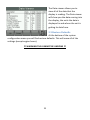
1
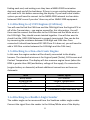
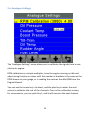
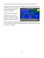
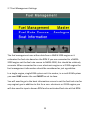
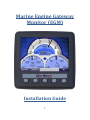
Marine Engine Gateway
Monitor (EGM)
Installation Guide
1
Contents
1.
Installing the Displays ............................................................................... 3
1.1 Mounting the Display .............................................................................. 3
1.2 Power Connections to the Display (all engine types) ............................. 3
1.3 Attaching to NMEA 2000 (optional) ........................................................ 3
1.4 Attaching to a J1939 Engines (CAN-bus) ................................................. 4
1.5 Attaching to an Engine via Analogue Signals .......................................... 4
1.6 Attaching to a Rudder Angle Sender ....................................................... 4
1.7 Attaching to a Fuel Level Sender............................................................. 5
1.8 Attaching to a Trim/Tilt Sender............................................................... 5
1.9 Attaching to a GPS NMEA 0183 Signal .................................................... 5
2 Commissioning the System ............................................................................ 6
2.1 ‘System Configuration’ Menu ................................................................. 6
2.2 Engine ID ............................................................................................. 7
2.2 Data Sources ....................................................................................... 7
2.3 NMEA 2000 Settings............................................................................ 9
2.4 J1939 Settings ................................................................................... 10
2.5 Analogue Settings ............................................................................. 11
2.6 Fuel Management Settings ............................................................... 13
2.7 Diagnostics ........................................................................................ 14
2
1. Installing the Displays
The EGM supports up to three engine types (Non-electric, J1939 or NMEA
2000) and each display can be allocated to be Port (or single), Starboard or
Centre. When mounting the displays the allocation of position is not
important as this is done during the commissioning sequence. Multi station
capability is a built-in feature and is provided across the NMEA 2000 network
using the gateway function. Adjustable items like language selection and
backlight are shared across the network so that all displays are synchronised
with the same settings.
1.1 Mounting the Display
Contained in the box you have received is a Fixing template, place this on the
area where the display is to be fitted, and use it to mark the holes in the
Dash, Fit the studding, from the “Fitting Kit” supplied, into the four positions
at the rear of the display. Make sure the Rubber Seal is securely in place at
the rear of the display over the USB Port access and then feed the studding
through the four holes and use the nuts to fix the display in place. The display
has an integrated rubber gasket to help seal the display to the dash.
Depending on access you may also need to fit the supplied cable harness to
the display before mounting the display.
1.2 Power Connections to the Display (all engine types)
The display can be powered from the engine battery, this way the display will
be able to monitor the engine battery voltage, however, while the engine is
cranking the display may cut out. Alternatively you can connect the display to
the domestic battery supply; this will prevent cut outs while the engine is
cranking. In either case the supply is fed via the black and red wires on the
harness (there are two blacks and either can be used). The supply should be
fused at 500mA or 1A max to protect the wiring.
1.3 Attaching to NMEA 2000 (optional)
Find the NMEA 2000 backbone if already fitted on the vessel, and use a TPiece to connect the NMEA 2000 Cable from the display to the backbone. You
should check that the NMEA backbone is properly terminated, you do this by
3
finding each end, and making sure they have a NMEA 2000 termination
device at each end of the backbone. If there is no pre-existing backbone you
will need to fit this before connecting the display. If you have a dual station
system you will need to connect to the NMEA 2000 network to share data
between EGM’s even if you don’t have any other NMEA 2000 equipment.
1.4 Attaching to a J1939 Engines (CAN-bus)
You will need to find the CAN-Low and the CAN-High from the Engine ECU or
off of the Transmission – see engine manual for this information. You will
then need to connect the Blue wire to the CAN-Low and the White wire to
the CAN-High. They should remain twisted together. You will also want to
check that the J1939 CAN Network is properly terminated. (You can do this
by measuring the resistance between CAN-High and CAN-Low. Once
connected it should read around 90-150 Ohms if it does not, you will need to
add a 120 Ohm resistor between the CAN-High and the CAN-Low).
1.5 Attaching to a Non-electronic Engine
In this case the engine senders will be directly connected to the display
harness. The standard minimum is for Engine Speed (Tacho), Oil Pressure and
Coolant Temperature. The display will also measure engine hours (when the
RPM is greater than 400) and battery voltage of the supply it’s connected to
(engine battery or domestic) without additional connections as these are
Automatic.
Wire
Black/White
Brown/White
Red/White
Yellow
Violet
Sensor Signal
Oil Pressure
Coolant Temperature
Boost Pressure
Oil Temperature
Tachometer (from Alternator W)
1.6 Attaching to a Rudder Angle Sender
The rudder angle can be measured from the Veethree rudder angle sender.
Connect the signal from the sender to the Yellow/White wire of the display
4
harness. The rudder sensor ground is connected to the spare black wire from
the display (used for all analogue senders).
1.7 Attaching to a Fuel Level Sender
The fuel level (one tank per display) can be measured from standard two wire
fuel senders. The sender signal should be connected to the blue wire of the
display harness. The sender ground is connected to the spare black wire from
the display (used for all analogue senders).
1.8 Attaching to a Trim/Tilt Sender
The tilt/trim (one per display) can be measured from standard two wire
tilt/trim senders. The sender signal should be connected to the orange wire
of the display harness. The sender ground is connected to the spare black
wire from the display (used for all analogue senders).
1.9 Attaching to a GPS NMEA 0183 Signal
A NMEA 0183 GPS can be attached to the unit to allow is to display SOG
(speed over ground) and COG (course over ground). The NMEA 0183 transmit
of the GPS should be linked with the green wire of the display harness.
5
2 Configuring System Settings
On completion of section 1, you are now ready to commission the system
which will involve accessing the menu items described below to configure the
various options.
But first you will apply power to the system and check that the display(s) all
power up correctly. Refer to the user manual to set up standard user settings.
For installation settings hold key 5 and enter the system configuration menu.
2.1 ‘System Configuration’ Menu
The ‘System Configuration’ menu is used to set up where the display will
receive all of its information and how the display will respond to the
information it receives.
The ‘System Configuration’ menu also contains several sub-menus, including:
•
•
•
Data Sources.
NMEA 2000 Settings.
J1939 settings.
6
•
•
•
•
Analogue Settings.
Fuel Management.
Diagnostics.
Restore defaults.
2.2 Engine ID
The engine ID can be changed to either port/single engine, starboard engine
or a centre engine, select the option that correctly describes the engine that
the display is connected to.
2.3 Data Sources
The ‘Data Source’ menu allows you to change where the display receives its
data from. You are able to change these data types; engine, battery, fuel
level, speed and rudder angle to read information from; NMEA 2000 (0183
for Speed), J1939 or analogue senders and also an option for a demo mode
on each data group. (Not all options are available for each setting)
To configure the display you will need to select the correct data source for
each sub heading by scrolling through the options with key 4. For example, if
you have an analogue engine but speed is transmitted over NMEA 0183, you
7
will need to set the engine settings to analogue and the speed setting to
NMEA 0183.
8
2.4 NMEA 2000 Settings
In this menu you can choose the fluid level instance that is read from the
NMEA 2000 network by the display. You can also, choose whether the
gateway will be enabled or disabled, if enabled it transmits based on its
Engine ID.
The fluid level is used to ‘tag’ the fuel level reading if you have multiple fuel
tanks and fuel senders. Instance 1 is used for Port or Single Tank and Instance
2 is used for Starboard tank.
9
2.5 J1939 Settings
Source Address One: This is the Address of the J1939 Engine, and is used to
Restrict what sources the EGM will accept J1939 from. It can also be set to
GLB which means it will accept data from any source.
Source Address Two: this functions the same way as Source Address one, but
is normally used for the Alternator.
SPN VERSION: Set the Suspect Parameter Number [Version 1, 2 or 3]. Version
4 is automatically detected, but older engines will have to be set to 1, 2 or 3.
Note. Consult your engine supplier to establish which SPN version is
appropriate if you have problems reading alarm data.
DISPLAY ADDRESS: As mentioned previously, every device has a unique
address and the Engine Monitor is no different. In single engine setups the
default display address is 40 (SAE recommendation). If the Engine Monitor
does not display all necessary data (which is supported) please contact your
engine manufacturer for advice on the value of this setting.
10
2.6 Analogue Settings
The ‘Analogue Settings’ menu allows you to calibrate the signals from a nonelectronic engine.
RPM calibration is a simple multiplier, have the engine running on idle and
adjust using the plus or minus until the number in brackets is the same as the
RPM shown on your gauge, or is reading the same as the idle RPM from the
Engine Manual.
You can use the arrow key’s to select, and the plus key to enter the next
screen to calibrate the rest of the channels. Once in the calibration screen,
for convenience, you can push Key 1, and it will move to the next channel.
11
The screen title shows you which channel you have selected at the top.
You then have three settings you can change, it also shows you the raw value
the EGM is measuring, as well as
the final data value, based on
the chosen calibration.
The first setting is if there is a
Gauge present. The second
setting is a description of the
calibration table. This should be
changed to match your setup.
The last setting is only really applicable if you have a gauge connected, and
can be used once the table is selected to adjust the output value until it reads
the same as your gauge.
12
2.7 Fuel Management Settings
The fuel management uses either data from a NMEA 2000 engine or it
estimates the fuel rate based on the RPM if you are connected to a NMEA
2000 engine set the fuel rate source to NMEA 2000, this should be relatively
accurate. When connected to a non- electronic engine or a J1939 engine the
fuel management information should be considered as just a guideline.
In a single engine, single EGM system set it to master, in a multi EGM system
you need ONE master the rest MUST be set to slave.
You will need to go to the boat information screen to set the fuel tank size for
any engine type in addition to this for a non- electronic or J1939 engine you
will also need to input a known RPM and an estimated fuel rate at that RPM.
13
2.8 Diagnostics
The ‘Diagnostics Menu’ allows you to view all of the information that your
display is receiving from every network input.
The CAN viewer will allow you to check if and where the raw CAN data is
being received and sent to.
The UART viewer will allow you to view the raw NMEA 0183 data that is being
received.
The IO Debug Screen will allow
you to view all of the inputs and
outputs, this screen can be used
to check the display for any bugs.
You can change between
analogue and digital
inputs/outputs by selecting
between buttons 1-3.
14
The Data viewer allows you to
view all of the data that the
display is reading. The Data viewer
will show you the data coming into
the display, the units the data is
displayed in and where the unit is
getting its data from.
2.9 Restore Defaults
At the bottom of the system
configuration menu you will find restore defaults. This will erase all of the
settings (except engine hours).
!!! WARNING THIS CANNOT BE UNDONE !!!
15