1
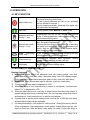
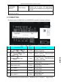
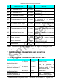
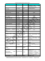
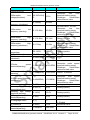
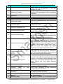
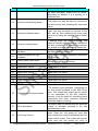
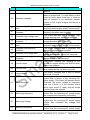
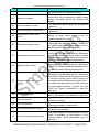
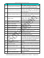
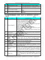
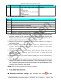
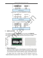
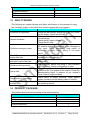
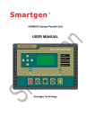
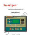
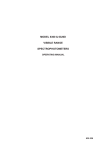
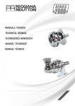
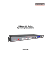
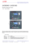
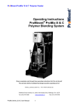
HGM6310D/6320D
AUTOMATIC GENERATOR MODULE
USER MANUAL
SMARTGEN ELECTRONIC
Smartgen Electronic Equipment Co., Ltd
No. 28 Jinsuo Road
Zhengzhou
Henan Province
P.R.China
Tel: 0086-371-67988888/67981888
0086-371-67991553/67992951/67992952
0086-371-67981000(overseas)
Fax: (0086)-371-67992952/67981000
Web:
http://www.smartgen.com.cn
http://www.smartgen.cn
Email: [email protected]
All rights reserved. No part of this publication may be reproduced in any material
form (including photocopying or storing in any medium by electronic means or other)
without the written permission of the copyright holder.
Applications for the copyright holder‟s written permission to reproduce any part of
this publication should be addressed to Smartgen Electronics at the address above.
Any reference to trademarked product names used within this publication is owned
by their respective companies.
Smartgen electronics reserves the right to change the contents of this document
without prior notice.
Software Version
Date
Version Note
2008-12-24 1.0
Original release.
2010-10-13 2.1
Modify the case images and the typical applications.
HGM6310D/6320D Automatic generator module
CONTENT
1
SUMMARY ...................................................................................................... 4
2
PERFORMANCE AND CHARACTERISTICS ................................................. 4
3
SPECIFICATION ............................................................................................. 6
4
OPERATION ................................................................................................... 7
4.1 KEY FUNCTION .................................................................................. 7
4.2 AUTOMATIC OPERATION .................................................................... 7
4.3 MANUAL OPERATION.......................................................................... 8
4.4 VIEWING THE EVENT LOG .................................................................. 9
5
PROTECTION ................................................................................................. 9
5.1 WARNINGS ......................................................................................... 9
5.2 SHUTDOWN ALARM .......................................................................... 10
5.3 ELECTRICAL TRIPS .......................................................................... 11
6
CONNECTING .............................................................................................. 12
7
PROGRAMMING PARAMETERS AND DEFINITION.................................... 14
7.1 CONFIGURABLE PARAMETERS AND SCOPE TABLE ........................... 14
7.2 PROGRAMMABLE OUTPUT PORT 1-6 DEFINITION CONTENT TABLE ... 18
7.3 PROGRAMMABLE INPUT PORT 1-6 DEFINITION CONTENT TABLE ...... 24
7.4 USER-DEFINED ITEMS ...................................................................... 25
7.5 SENSORS SELECT ........................................................................... 26
7.6 START-UP SUCCESS ........................................................................ 27
8
PARAMETER EDITING ................................................................................. 27
9
COMMISSIONING ......................................................................................... 29
10
TYPICAL WIRING DIAGRAMS ..................................................................... 30
11
INSTALLATION ............................................................................................. 31
12
FACTORY DEFAULT VALUES ..................................................................... 32
13
FAULT FINDING ........................................................................................... 34
14
PRODUCT PACKAGE .................................................................................. 34
HGM6310D/6320D Auto generator module
ISSUE2010-10-13 Version2.1
Page 3 of 34
HGM6310D/6320D Automatic generator module
1 SUMMARY
HGM6310D/6320D is an automatic genset controller, which assembles
digitization, intelligentization and networked techniques. It is used in automatic
and monitor control system of unit set diesel genset to achieve automatic
start/stop, data measure, alarm protection and „three remote‟ functions (remote
control, remote monitoring, remote communication). The controller adopts large
liquid crystal display (LCD) and selectable Chinese and English interface with
easy and reliable operation.
HGM6310D/6320D genset automatic controllers adopt microprocessor technique
with precision measurement of multi-parameters, fixed value adjustment, time
setting and threshold adjusting and etc.. It can be widely used in all types of
automatic genset control system with compact structure, advanced circuits,
simple connections and high reliability.
2 PERFORMANCE AND CHARACTERISTICS
◙
HGM6300D series controller has two types:
HGM6310D: ASM (Automatic Start Module)
HGM6320D: Based on HGM6310D, it adds mains AC monitoring,
Mains/Genset automatic switching control functions (AMF), especially suitable
for the automatic system composed by Mains and Genset.
◙ Microprocessor control, big screen LCD with back-lit display, selectable
Chinese and English interface, touch button operation.
◙ Power supply range: (8~35) VDC, can adapt to12/24V start battery voltage
environment.
◙ With dual water temperature, dual oil pressure sensor input.
◙ Precise testing function: almost can realize all the related electricity parameter
and nonparametric detection.
Mains electric quantity items:
3 phase voltage Ua, Ub, Uc
V
3 phase current Ia, Ib, Ic
A
Frequency F1 Hz
Active power PA kW
Apparent power PR
kVA
Power factor
PF
Generator electric quantity items:
3 phase voltage Ua, Ub, Uc V
3 phase current Ia, Ib, Ic A
Frequency F1 Hz
Active power PA kW
Apparent power PR kVA
Power factor PF
HGM6310D/6320D Auto generator module
ISSUE2010-10-13 Version2.1
Page 4 of 34
HGM6310D/6320D Automatic generator module
Accumulate electric energy kWh
Engine parameter items:
Coolant temperature WT ºC/ºF display sync
Oil pressure OP kPa/Psi/Bar display sync
Speed RPM
Plant battery voltage V
Hour count (HC) can accumulate 999999 hours.
Starting up can accumulate Max.999999 times.
The abnormal condition of mains and generating electricity:
Over voltage
Under voltage
Over frequency
Under frequency
Loss of phase
Loss of electricity
Fault display and protection function items:
High temperature pre-alarm
High temperature shutdown alarm
Low oil pressure pre-alarm
Low oil pressure shutdown alarm
Over speed shutdown alarm
High cabinet temperature warn
Low fuel level warn
High voltage warn
Low voltage warn
Over current shutdown alarm
Fail to start alarm
Shutdown failure
Emergency stop alarm
Oil pressure sensor open circuit shutdown alarm
◙ Integrity of protection function can realize diesel genset Auto start/stop, load
transfer and alarm protection.
◙ With real calendar, clock and accumulation of running time, can save 99 sets
of history records to make facilities faults diagnosis possible. This history
record can detect in locale, or via PC to detect and print.
◙ Can set a regular time in each month or each week to startup or shutdown.
◙ Display electric energy of genset cumulated output, can manage oil
consumption of genset.
◙ The controller can be set for engine controller via software, that is, no
monitor/display generator electricity parameter; it is fit for controlling pump
unit.
◙ Multiple temperature, pressure and oil level sensor can be used, and
parameter can be defined by users.
◙ With international standard MODBUS communication protocol, better fault
HGM6310D/6320D Auto generator module
ISSUE2010-10-13 Version2.1
Page 5 of 34
HGM6310D/6320D Automatic generator module
◙
checking capability, and with RS232/RS485 communication interface, can
realized functions of remote control, remote measure, remote message of
genset, to achieve remote centralization monitoring.
Modular design, anti-flaming ABS plastic shell, inserted-type connection
terminals and built-in mounting. Structure compact with easy mounting.
3 SPECIFICATION
ITEM
CONTENT
Operating voltage
DC8. 0V to 35. 0V, Continuous Power Supply
Power consumption
<3W(Standby mode: ≤2W)
Alternator Input Range
3-Phase 4 Wire
3-Phase 3 Wire
Single-Phase 2 Wire
2-Phase 3 Wire
20V AC - 360 VAC (ph-N)
30V AC - 600 VAC (ph- ph)
20V AC - 360 VAC (ph-N)
20V AC - 360 VAC (ph-N)
Alternator Input Frequency
50Hz - 60Hz
Magnetic Volt Input Range
1.0V to 24.0V (RMS)
Magnetic Input Frequency
10,000 Hz (max)
Start Relay Output
16 Amp DC28V at DC supply output.
Fuel Relay Output
16 Amp DC28V at DC supply output.
Auxiliary Relay Output (1-4)
(1-3)16Amp DC28V at DC supply
(4)16Amp 250VAC passive output.
output,
Close Generator Relay
16Amp 250VAC passive
Programmable Relay Output 5
Close Mains Relay
16Amp 250VAC passive
Programmable Relay Output 6
Overall Dimensions
240mm x 172mm x 57mm
Panel Cutout
214mm x 160mm
C. T. Secondary
5A (rated)
Operating Temp. Range
Temperature: (-25~70)°C
Humidity: (20~90)%
Storage Condition
Temperature: (-40~+70)°C
Protective Level
IP55: when with waterproof rubber ring added
between controller and its panel.
IP42: when without waterproof rubber ring between
controller and its panel.
Insulation Intensity
Object: between input/output/power
Quote standard: IEC688-1992
Test way: AC1.5 kV/1min 3mA leakage current
Weight
0.85kg
HGM6310D/6320D Auto generator module
ISSUE2010-10-13 Version2.1
Page 6 of 34
HGM6310D/6320D Automatic generator module
4 OPERATION
4.1 KEY FUNCTION
Stop/ Reset key
Can stop generator under mode of Manual/Auto;
Can reset alarming under Stop;
To test if panel indicators are OK or not,( pressing
this key at least 3 seconds );
During stopping process, pressing this again can
stop generator immediately.
Start key
To start genset under Manual or Auto mode.
Manual mode key/
Config. „-‟ key
Pressing this key will set the module into manual
mode. In setting parameter status, pressing this key
will decrease setting value.
Pressing this key when the mains are on load will
open the mains load switch.
Manual test mode/ Pressing this key when the generator is on load and
Config. „+‟ key
the mains are healed will open the generator load
switch. Wait for the duration of the transfer delay,
then close the mains load switch.
Pressing this key will set the module into automatic
Auto
key/config.
mode. In setting parameter status, pressing this key
„enter‟ key
will shift cursor or confirm setting value.
Pressing this key will view shutdown history
View event log
records. Again pressing this key will quit.
Page down
/decrease
Page down, or in setting parameter status, pressing
this key will decrease setting value.
4.2 AUTOMATIC OPERATION
Starting Sequence
1) HGM6320D, When Mains are abnormal (over and under voltage, over and
under frequency), enter into mains “abnormal delay” and LCD display begins
count down time. When mains abnormal delay is over, enter into “start delay”.
2) HGM6310D, when remote start input is effective, enter into “start delay”.
3) “Count-down” of start delay is displayed in LCD.
4) When start delay is over, preheat relay is output (if configured), “pre-heat start
delay XX s” is displayed in LCD.
5) When pre-heat relay is over, fuel relay is output 1s and then start relay-output; if
genset starting fails during “cranking time”, the fuel and start relays stop output
and enters into “crank interval time” to wait for next attempt.
6) If genset fails in starting within setting times, the first line of LED will turn black
and start failure alarm will be displayed.
7) If it starts successfully, it will enter into “safe runtime”. During this period, alarms
of low oil pressure, high temperature, under speed, charge failure and etc. are
inactive. Enter into “start idle delay” after safety run delay (if start idle delay is
HGM6310D/6320D Auto generator module
ISSUE2010-10-13 Version2.1
Page 7 of 34
HGM6310D/6320D Automatic generator module
configured).
8) During “start idle delay”, alarms of under speed, under frequency, under voltage
alarm are inactive. As soon as this start idle delay is over, genset will enter into
“warming up delay” (if high speed warming delay is configured).
9) When “warming up delay” is over, if generator normal, then indicator lamp
illuminates. If generator voltage and frequency reach load requirement, genset
close relay is output, genset is on load, generator supply power indicator lamp
illuminates, then genset will enter into normal running status; if genset voltage or
frequency is abnormal, the controller will alarm to shutdown (gens alarm is
displayed in LCD).
Stopping Sequence
HGM6320D, if mains turns normal during genset is running, enter into mains
voltage “normal delay” and its indicator illuminates after mains is confirmed
normally, “Start delay” is beginning.
1) HGM6310D, genset enters into “stop delay” as soon as “Remote Start” input is
inactive.
2) After stop delay ends, enter “high speed coolant delay”, and generator close
relay is disconnected, after “switch transfer delay”, mains close relay output,
mains is on-load, generator power supply indicator lamp isn‟t illuminating, and
mains power supply indicator lamp illuminates.
3) Idle relay is power-on output when the controller enters “idle stop delay”.
4) Enter into “ETS relay”, ETS shutdown relay is power-on output. Fuel relay
output is disconnected.
5) Genset can automatically judge if it is steady when the controller enters “Genset
stop steady time”.
6) After genset stops steadily, enter generator standby status; if genset does not
stop, then controller will alarm (LCD screen display shutdown failure warn).
4.3 MANUAL OPERATION
1) HGM6320D Auto start mode is active when press
illuminates. Press
key and its indicator
key, then controller enters “Manual Test Mode” and
indicator illuminates. Under the both modes, press
key to start genset, and
it automatically detects if it starts successfully and accelerate high speed
running. With high temperature, low oil pressure, over speed and voltage during
diesel genset running, controller can protect genset to stop effectively and
quickly (please refer to No.4~9 of auto start operation for more details). Under
“Manual Test Mode
”, genset on-load is decided by whether mains are
normal or not. If mains are normal, loading switch isn‟t transferred; while mains
HGM6310D/6320D Auto generator module
ISSUE2010-10-13 Version2.1
Page 8 of 34
HGM6310D/6320D Automatic generator module
are abnormal, loading switch is transferred into gens side. Under “Manual Test
Mode
“, after genset runs well in high speed, no matter mains is normal or
not, loading switch must be transferred into Gens.
2) HGM6310D Auto start mode is active when press
illuminates. Then press
key, and its indicator is
key to start generator, it automatically detects if it is
started successfully and genset automatically accelerates high speed running.
With high temperature, low oil pressure, over speed and voltage abnormal
during diesel genset running, controller can protect genset to stop effectively
and quickly (please refer to No.4~9 of Auto start operation for more details).
After genset runs well in high speed, controller will send signal of Gens close.
3) Manual stop, press
key can shutdown the running genset (please refer to
No.3~7 of AUTO stop operation for more details).
4.4 VIEWING THE EVENT LOG
In the control panel, press
key to view previous abnormal shutdown records of
the controller, including shutdown warning and corresponding time. Press
to view back records. Again press
key
key to return real time display status of the
controller. HGM6310D/6320D controller can save recent 99 pieces of abnormal
shutdown records.
5 PROTECTION
5.1 WARNINGS
Warnings are non-critical alarm conditions and do not affect the operation of
the generator system. They serve to draw the operators‟ attention to an
undesirable condition.
DISPLAY
REASON
The module detects that the engine coolant temperature has
ENGINE HIGH
exceeded the high engine temperature pre-alarm setting level
TEMPERATURE
after the Safety On timer has expired.
The module detects that the engine oil pressure has fallen
LOW
OIL
below the low oil pressure pre-alarm setting level after the
PRESSURE
Safety On timer has expired.
The engine speed has risen above the over speed pre-alarm
OVERSPEED
setting
HGM6310D/6320D Auto generator module
ISSUE2010-10-13 Version2.1
Page 9 of 34
HGM6310D/6320D Automatic generator module
DISPLAY
REASON
The engine speed has fallen below the under speed pre alarm
UNDERSPEED
setting.
LOSS
OF If the speed sensing signal is lost during cranking, a warning
SPEED SIGNAL will occur.
GENERATOR
The generator output frequency has risen above the pre-set
OVER
pre-alarm setting.
FREQUENCY
GENERATOR
The generator output frequency has fallen below the pre-set
UNDER
pre-alarm setting after the Safety On timer has expired.
FREQUENCY
GENERATOR
The generator output voltage has risen above the pre-set
OVER
pre-alarm setting.
VOLTAGE
GENERATOR
The generator output voltage has fallen below the pre-set
UNDER
pre-alarm setting after the Safety On timer has expired.
VOLTAGE
GENERATOR
If the module detects a generator output current in excess of
OVER
the pre-set trip a warning alarm initiates.
CURRENT
The module has detected a condition that indicates that the
FAIL TO STOP
engine is running when it has been instructed to stop.
LOW
FUEL The level detected by the fuel level sensor is below the low
LEVEL
fuel level setting.
The auxiliary charge alternator voltage is low as measured
CHARGE
from the W/L terminal. “Charging failure warning” will display
FAILURE
in LCD screen.
BATTERY
The DC supply has fallen below the low volts setting level for
UNDER
the duration of the low battery volts timer.
VOLTAGE
BATTERY OVER The DC supply has risen above the high volts setting level for
VOLTAGE
the duration of the high battery volts timer.
AUXILIARY
Auxiliary inputs can be user configured and will display the
INPUT
message as written by the user.
5.2 SHUTDOWN ALARM
When controller detects shutdown alarms, it will shut down immediately and
disconnect Gens close relay signals to disengage load. The alarms are displayed in
LCD.
DISPLAY
REASON
The emergency stop button has been depressed. This is
EMERGENCY STOP a failsafe input and will immediately stop the genset. It
will be displayed in LCD.
HGM6310D/6320D Auto generator module
ISSUE2010-10-13 Version2.1
Page 10 of 34
HGM6310D/6320D Automatic generator module
DISPLAY
REASON
The engine coolant temperature has exceeded the high
ENGINE
HIGH engine temperature trip setting level after the Safety On
TEMPERATURE
timer has expired, and it will be displayed in LCD.
The engine oil pressure has fallen below the low oil
OIL pressure trip setting level after the Safety On timer has
expired, and it will be displayed in LCD.
LOW
PRESSURE
OVERSPEED
UNDERSPEED
LOSS OF
SIGNAL
The engine speed has exceeded the pre-set trip, and it will
be displayed in LCD.
The engine speed has fallen below the pre-set trip after
the Safety On timer has expired, and it will be displayed in
LCD.
SPEED The speed signal from the magnetic pickup is not
being received by the DSE controller.
GENERATOR OVER The generator output frequency has risen above the
FREQUENCY
preset level, and it will be displayed in LCD.
GENERATOR
The generator output frequency has fallen below the
UNDER
preset level.
FREQUENCY
GENERATOR OVER The generator output voltage has risen above the preset
VOLTAGE
level.
GENERATOR
UNDER VOLTAGE
GENS
CURRENT
OVER
FAIL TO START
The generator output voltage has fallen below the preset
level.
When controller detects that genset current is over
pre-set alarm or delay is not 0, it will send stop alarm
signal and it will be displayed in LCD.
The engine has not fired after the preset number of start
attempts.
OIL
PRESSURE
The oil pressure sensor is detected as not being present
SENSOR
OPEN
(open circuit).
CIRCUIT
An active auxiliary input configured as a shutdown will
AUXILIARY INPUTS cause the engine to shut down. The display shows the text
as configured by the user.
5.3 ELECTRICAL TRIPS
Electrical trips are latching and stop the Generator but in a controlled manner. On
initiation of the electrical trip condition the module will de-energies the ‘Close
Generator’ Output to remove the load from the generator.
DISPLAY
RANGE
REASON
If a generator output in excess of the high
current alarm point, a warning alarm
GENERATOR
occurs. If this high current condition
OVER
Always active
continues for an excess period, then the
CURRENT
alarm escalates to either a shutdown or
electrical trip condition.
HGM6310D/6320D Auto generator module
ISSUE2010-10-13 Version2.1
Page 11 of 34
HGM6310D/6320D Automatic generator module
If an auxiliary input configured as an
electrical trip is active, the appropriate
User settings
message will be displayed as configured by
the user.
Note:-Types of input trip alarm quantity must be configured by users, and then
input port is active.
AUXILIARY
INPUTS
6 CONNECTING
The back panel of HGM6310D and HGM6320D controller is shown as follows:
PIN
DESCRIPTION
CABLE
SIZE
1
DC Plant Supply Input (B-)
2.5mm
2
DC Plant Supply Input (B+)
2.5mm
3
Emergency Stop input
2.5mm
4
Fuel output relay
2.5mm
5
Start output relay
2.5mm
6
Aux. output 1
2.5mm
7
Aux. output 2
2.5mm
8
Aux. output 3
2.5mm
HGM6310D/6320D Auto generator module
NOTES
System DC negative input.
(Battery negative).
System DC positive input.
(Battery positive). (Recommended
maximum fuse 20A)
Plant supply +ve. Also supplies fuel
& start outputs. (Recommended
maximum fuse 32A)
Plant supply +ve from pin 3.
16 Amp rated.
Plant supply +ve from pin 3.
16 Amp rated.
Plant supply +ve.
16 Amp rated.
Plant supply +ve.
16 Amp rated.
Plant supply +ve.
16 Amp rated.
ISSUE2010-10-13 Version2.1
Page 12 of 34
HGM6310D/6320D Automatic generator module
PIN
DESCRIPTION
CABLE
SIZE
NOTES
Do not connect to ground (battery
–ve)
Switch to -ve
Switch to -ve
Switch to -ve
Switch to -ve
Switch to -ve
Switch to -ve
Connect to a good clean GND
point.
9
Charging fail / excite
1.0mm
10
11
12
13
14
15
Aux. input 1
Aux. input 2
Aux. input 3
Aux. input 4
Aux. input 5
Aux. input 6
1.0mm
1.0mm
1.0mm
1.0mm
1.0mm
1.0mm
16
Magnetic common GND
1.0mm
17
Magnetic pickup B +
1.0mm
18
19
20
21
22
23
Magnetic pickup BOil Pressure sensor 2 input
1.0mm
1.0mm
Aux. output 4
2.5mm
RS485 common GND
0.5mm
24
25
26
RS485 +
RS485 Not connected
0.5mm
0.5mm
-
27
28
48
Aux. output 6
(Close mains relay output)
2.5mm
Free voltage contacts, N/C, 16 Amp
rated.
Aux. output 5
(Close generator output)
2.5mm
Free voltage contacts, N/O, 16 Amp
rated.
29
30
31
32
33
34
35
36
37
Mains A voltage
monitoring
Mains B voltage
monitoring
Mains C voltage
monitoring
Mains Neutral input
Generator A voltage
monitoring
Generator B voltage
monitoring
Generator C voltage
monitoring
1.0mm
1.0mm
1.0mm
1.0mm
1.0mm
1.0mm
1.0mm
38
Generator Neutral input
1.0mm
39
CT Secondary for A
2.5mm
HGM6310D/6320D Auto generator module
Connect to magnetic pickup device.
Connect to oil pressure sensor 2.
Free voltage
rated.
contacts.
16Amp
Use only 120Ω RS485 approved
cable.
Connect to mains A output
(Recommend 2A fuse)
Connect to mains B output
(Recommend 2A fuse)
Connect to mains C output
(Recommend 2A fuse)
Connect to mains neutral terminal
Connect to generator A output
(Recommend 2A fuse)
Connect to generator B output
(Recommend 2A fuse)
Connect to generator C output
(Recommend 2A fuse)
Connect to generator N line
terminal.
Connect to secondary of A
monitoring CT.
ISSUE2010-10-13 Version2.1
Page 13 of 34
HGM6310D/6320D Automatic generator module
PIN
DESCRIPTION
CABLE
SIZE
40
CT Secondary for B
2.5mm
41
CT Secondary for C
2.5mm
42
CT Secondary common
2.5mm
43
Temperature sensor 2 input
1.0mm
44
Oil Pressure sensor1 input
1.0mm
45
Temperature sensor 1 input
1.0mm
46
Liquid Level sensor input
1.0mm
47
Sensor common
1.0mm
RS232 connectors
0.5mm
RJ45 network
NOTES
Connect to secondary of B
monitoring CT.
Connect to secondary of C
monitoring CT.
Connect to secondary of all
monitoring CT‟s.
The temperature sensor input, can
be connected to an external
resistance sensor.
Oil pressure sensor input, can be
connected to an external resistance
sensor.
Temperature sensor 1 input can be
connected to an external resistance
sensor.
Liquid level sensor input, can be
connected to an external resistance
sensor.
Sensors common GND can connect
to casing or starting battery
cathode.
Communication with the computer
(2-RXD, 3-TXD, 5-GND)
Software
upgrades
port
(Manufacturers use)
Note: Prohibit removing starting battery when the engine is running, or it will
damage the control system because of over DC input voltage.
7 PROGRAMMING PARAMETERS AND DEFINITION
HGM6310D / 6320D generator controllers set parameters as follows:
7.1 CONFIGURABLE PARAMETERS AND SCOPE TABLE
Parameter
Range
01Low oil pressure 1
(1-399)kPa
threshold(warning)
02Low oil pressure 1
(0-398)kPa
threshold (shutdown) *3
03High temperature 1
(81-139)ºC
threshold(warning)
04 High temperature 1
(82-140)ºC
threshold (shutdown)*4
HGM6310D/6320D Auto generator module
Default
Remark
124kPa
Return: 138kPa
103kPa
Low
oil
pressure
1
threshold setting range:
Shutdown value < Warn
value<Return value
90ºC
Return: 88ºC
95ºC
High
temperature
threshold setting range:
ISSUE2010-10-13 Version2.1
Page 14 of 34
1
HGM6310D/6320D Automatic generator module
Parameter
05Fuel level threshold
(warning)
06 Start delay
07 Pre-heat delay
08 Crank time
09 Crank rest time
10 Safety run time
11Over
speed/
over
shoot delay
12 Start idle time
13 Warming up time
14 Transfer switch time
15 Return time
16 Coolant time
17 Stop idle time
18ETS Solenoid hold
time
19Waiting for steady stop
time
20Generator
transient
delay
21Mains transient delay
*1
Range
Default
Remark
Shutdown value > Warn
value>Return value
(0-100)%
10%
Analog quantity
(0-9999s)
(0-300s)
(3-60s)
(3-60s)
(5-60s)
5s
0s
8s
10s
10s
timer
timer
timer
timer
timer
(0-10s)
2s
timer
(0-3600s)
(0-3600s)
(0-600s)
(0-9999s)
(0-3600s)
(0-3600s)
10s
30s
2s
30s
60s
10s
timer
timer
timer
timer
timer
timer
(0-120s)
20s
timer
(10-120s)
30s
timer
(0-30s)
5s
timer
(0-30s)
2s
22Mains under voltage (50-360V/624)
(trip) *1
*2
184V
23Mains
(trip) *1
276V
over
voltage (50-360V/624)
*2
24Mains low frequency
(0-75Hz )
(trip) *1
45.0Hz
25Mains high frequency
(0-75Hz)
(trip) *1
55.0Hz
26Generator
voltage
(shutdown)
184V
27Generator
voltage(warning)
28Generator
under
(50-360V/624)
*2
under (50-360V/624)
*2
196V
over (50-360V/624)
265V
HGM6310D/6320D Auto generator module
Return: 207V
Return value>Under volts
trip value
Return: 253V
Return value<High volts
trip value
Return: 48.0Hz
Return value>Low freq. trip
value
Return: 52.0Hz
Return value<High freq. trip
value
Return: 207V
Generator
under
volts
threshold setting range:
Shutdown
value<Warn
value<On-load value
Return: 253V
ISSUE2010-10-13 Version2.1
Page 15 of 34
HGM6310D/6320D Automatic generator module
Parameter
voltage(warning)
29Generator
voltage(shutdown)
Range
*2
over (50-360V/624)
*2
30Generator
low
(0-74.8Hz)
frequency (shutdown)
Default
Remark
273V
Generator
over
volts
threshold setting range:
Shutdown
value>Warn
value>Return value
40.0Hz
31Generator
low
(0.1-74.9Hz)
frequency (warning)
42.0Hz
On-load value:45.0Hz
Generator
low
freq
threshold setting range:
Shutdown
value<Warn
value<On-load value
32Generator
high
(0.1-74.9Hz)
frequency (warning)
55. 0Hz
Return: 52. 0Hz
57.0Hz
Generator
high
freq
threshold setting range:
Shutdown
value>Warn
value>Return value
100%
Analog quantity
33Generator
high
(0.2-75Hz)
frequency(shutdown)
34Over
current
(50-120%)
percentage
35 Flywheel teeth
(10-500)
36Under speed threshold
(0-5998 RPM)
(shutdown)
118 teeth
1270RPM
37Under
speed
(1-5999 RPM)
threshold(warning)
1350 RPM
Return : 1380RPM
Generator under speed
threshold setting range:
Shutdown
value<Warn
value<On-load value
38 Over speed threshold
(warning)
1650 RPM
Return: 1620RPM
(1-5999 RPM)
(2-6000RPM)
1710RPM
40Over shoot percentage
41Battery low voltage
threshold(warning)
42Battery high voltage
threshold (warning)
43Charge
failure
threshold(warning)
(0-10%)
0
Generator
over
speed
threshold setting range:
Shutdown
value>Warn
value>Return value
Analog quantity
(0-39.9 V)
8.0V
Analog quantity
(0.1-40V)
33.0V
Analog quantity
(0-39V)
6.0V
Analog quantity
44 Language select
(0-1)
0
39 Over speed threshold
(shutdown)
45 Password
(0-9999)
46Low oil pressure 2
(1-399)kPa
threshold(warning)
HGM6310D/6320D Auto generator module
1234
0: Chinese
1: English
Numerical value
Not used
ISSUE2010-10-13 Version2.1
Page 16 of 34
HGM6310D/6320D Automatic generator module
Parameter
Range
Default
47Low oil pressure 2
(0-398)kPa
threshold(shutdown)
Not used
48High temperature
threshold (warning)
Not used
49High temperature
threshold (shutdown)
2
2
50 Current transformer
51Select oil pressure
sensor 1
52Select
temperature
sensor 1
53Select
fuel
level
sensor
54Select oil pressure
sensor 2
55Select
temperature
sensor 2
56 Module address
(81-139)ºC
(82-140)ºC
Not used
5-6000:5A
500A
1-14
VDO10 bar
1-13
VDO120ºC
1-11
VDO ohm
(10-180)
1-14
Not used
1-13
Not used
1-254
1
57 Select temperature
unit
0-1
ºC
58 Select pressure unit
0-1
kPa
Remark
Low
oil
pressure
2
threshold setting standard:
Shutdown value< Warn
value< Return value.
High
temperature
2
threshold setting standard:
Shutdown value> Warn
value > Return value.
Load value:500A
The controller is active
when temperature sensor 2
is configured.
The controller is active
when oil pressure sensor 2
is configured.
Note:
*1: HGM6310D controller doesn‟t possess the item.
*2: 360V for phase voltage, 624V for line voltage (3- phase 3 wire).
*3: Low oil pressure (shutdown) setting value is 0 without shutdown.
*4: High temperature (shutdown) setting value is 140 without shutdown.
Other parameters configuration: They can be only configured via PC software (as
follows).
Parameter
Default
Alternator AC voltage sensing
Yes
Generator pole number
4
Magnetic Pickup Select
Yes
AC system
3-phase 4 wire
Fast on load mode
No
Crank times
3
Open mains breaker when
Inactive(only HGM6320D use)
Mains is short-time abnormal
Voltage transformer
No
HGM6310D/6320D Auto generator module
ISSUE2010-10-13 Version2.1
Page 17 of 34
HGM6310D/6320D Automatic generator module
Parameter
Fuel pump control
Digital input1
Digital input2
Digital input3
Digital input4
Digital input5
Digital input6
Digital output1
Digital output2
Digital output3
Digital output4
Digital output5
Digital output6
LED1
LED2
LED3
LED4
Over Current Delay multiplier
Action (over current)
Generator frequency
(crank disconnect)
Engine speed
(crank disconnect)
Oil pressure
(crank disconnect)
Detect oil pressure during
cranking
Schedule start genset
Default
No
Remote start on load, close to activate.
High temperature input, shutdown, close to activate
(activate from safety on).
Low oil pressure input, shutdown, close to activate
(activate from safety on).
Low oil pressure inputs, warning, close to activate,
(always activate).
High oil temperature input, shutdown, close to
activate (activate from safety on).
Exterior alarm input, shutdown, close to activate
(always activate).
Pre-heat output (during pre-heat timer).
Common alarm
ETS solenoid output
Idle /Run speed control
Close generator
Close mains (HGM6320D)
Not used (HGM6310D)
System in Auto mode
Fail to start
Common shutdown alarm
Common alarm
36
Electrical trip
15Hz
450RPM
Not used
Yes
No
7.2 PROGRAMMABLE OUTPUT PORT 1-6 DEFINITION CONTENT
TABLE
NUM
CONTENT
1
Not Used
2
Air flap control
3
Audible alarm
4
Battery high voltage
HGM6310D/6320D Auto generator module
DESCRIPTION
When over speed alarm shutdown and
emergency stop is active, can turn off air flap.
When warning, shutdown, electrical trip is
active, can connect exterior alarm, can
configure input port “Audible alarm”.
The DC supply has risen above the high volts
ISSUE2010-10-13 Version2.1
Page 18 of 34
HGM6310D/6320D Automatic generator module
NUM
CONTENT
5
Battery low voltage
6
7
8
Reserved
Reserved
Reserved
9
Crank relay output
10
Fuel relay output
11
Calling for scheduled run
12
Charging alternator fails
13
Close Generator output
14
Close Generator pulse output
15
Close Mains output
16
Close Mains pulse output
17
18
19
20
21
Common
under
&
over
Frequency shutdown
Common
under
&
over
Frequency warning
Common under & over voltage
shutdown
Common under & over voltage
warning
Common alarm
HGM6310D/6320D Auto generator module
DESCRIPTION
setting level for the duration of the high
battery volts timer
The DC supply has fallen below the low volts
setting level for the duration of the low battery
volts timer
Operation of generator start, disconnect after
start success.
When generator start is active, disconnect of
waiting stop steady.
The controller operates when scheduler start
is active, or inactive.
The controller is active when generator
charges failure alarm.
This output source is intended to be used to
control the load switching device. Whenever
the 6300D module selects the generator to be
on load this control source will be active.
This output source is intended to be used to
control the load switching device. Whenever
the 6300D module selects the mains to be on
load, this control source will be active for the
duration of the „Breaker Close Pulse Timer‟.
Once this timer has expired, the output
source will once again become in-active.
This output source is intended to be used to
control the load switching device. Whenever
the 6320D module selects the mains to be on
load this control source will be active.
Whenever the 6320D module selects the
mains to be on load this control source will be
active for the duration of the „Breaker Close
Pulse Timer‟. Once this timer has expired, the
output source will once again become
in-active.
Either under frequency or over frequency
shutdown has been activated.
Either under frequency or over frequency
warning has been activated.
Either under voltage or over voltage
shutdown has been activated.
Either under voltage or over voltage warning
has been activated.
A warning, electrical trip or shutdown alarm
ISSUE2010-10-13 Version2.1
Page 19 of 34
HGM6310D/6320D Automatic generator module
NUM
CONTENT
22
Common electrical trip alarm
23
Common shutdown alarm
24
Common warning alarm
25
26
Coolant temperature high 1
pre-alarm
Coolant temperature high 1
shutdown
27
Cooling delay timer active
28
29
30
31
32
33
34
35
Reserved
Digital Input 1active
Digital Input 2active
Digital Input 3active
Digital Input 4active
Digital Input 5active
Digital Input 6 active
Emergency stop alarm
36
ETS solenoid shutdown output
37
Fail to start alarm
38
Fuel Pump Control
HGM6310D/6320D Auto generator module
DESCRIPTION
has been activated. Reset rules as above,
depending on whether it is a warning or a
shutdown fault.
An electrical trip alarm has been activated.
This output can only be reset by removal of
the fault and by then pressing the stop reset
button.
A shutdown alarm has been activated. This
output can only be reset by removal of the
fault and by then pressing the stop reset
button or by using an external „Alarm Reset‟
Input.
A warning alarm has been activated. This
output is normally self-resetting on removal of
the fault. However, it is possible to configure
the module such that the warning alarms are.
A high engine coolant temperature warning
(pre-alarm) has occurred.
a high engine coolant temperature shutdown
has occurred.
This output source will be active when the
cooling off-load timer is running.
Digital input 1 is active.
Digital input 2 is active.
Digital input 3 is active.
Digital input 4 is active.
Digital input 5 is active.
Digital input 6 is active.
An emergency stop alarm has occurred.
This output controls the fuel solenoid on an
ETS solenoid type generator, energizing for
the time period selected in the Edit Timer
Menu. The normal fuel output (pin 4) should
not be connected to the fuel solenoid,
however it can be used for controlling panel
instruments and other functions required
whilst the engine is running.
The engine has not started after the specified
number of attempts, selected in the edit
miscellaneous menu.
This output is used to control a fuel transfer
pump. Once the „fuel pump on‟ level has
been reached the module will activate the fuel
pump control output. This output will remain
active until the „fuel pump off‟ level is
ISSUE2010-10-13 Version2.1
Page 20 of 34
HGM6310D/6320D Automatic generator module
NUM
39
40
41
42
43
44
45
CONTENT
Generator available
Generator high Frequency
warn
Generator high Frequency
shutdown
Generator high voltage warn
Generator high voltage
shutdown
Generator low frequency
warn
Generator low frequency
shutdown
46
Generator low voltage warn
47
Generator low voltage
shutdown
48
Louvre control
49
Low fuel level
50
Loss of speed
51
Mains abnormal
52
Mains high frequency
53
Mains high voltage
54
Mains low frequency
HGM6310D/6320D Auto generator module
DESCRIPTION
reached.
This output indicates when the generator is
ready to accept load, i. e. after safety on and
warm up timers have timed out. It could be
used to connect to an automatic transfer
system or PLC to give a signal that the set is
available.
This output indicates that a generator high
frequency warning (pre- alarm) has occurred.
This output indicates that a generator high
frequency shutdown has occurred.
This output indicates that a generator high
voltage warning (pre- alarm) has occurred.
This output indicates that a generator high
voltage shutdown has occurred.
This output indicates that a generator low
frequency warning (pre- alarm) has occurred.
This output indicates that a generator low
frequency shutdown has occurred.
This output indicates that a generator low
voltage warning (pre- alarm) has occurred.
This output indicates that a generator low
voltage shutdown has occurred.
This output controls the opening of the
louvers on engine starting and closure when
engine has stopped.
This output indicates that the level of fuel has
fallen below the low fuel alarm trip point.
This output indicates that a loss of speed
alarm has occurred.
This output indicates that the module has
sensed that a failure of the incoming AC
mains supply. This output will become active
whenever the mains voltage or frequency
goes out of limits, or if the auxiliary mains
failure input active (if used) and the mains
transient timer has expired.
This output indicates that the module has
sensed that the incoming AC mains supply
has exceeded the frequency limit setting.
This output indicates that the module has
sensed that the incoming AC mains supply
voltage has exceeded the voltage limit
setting.
This output indicates that the module has
sensed that the incoming AC mains supply
ISSUE2010-10-13 Version2.1
Page 21 of 34
HGM6310D/6320D Automatic generator module
NUM
CONTENT
55
Mains low voltage
56
Low oil pressure 1 warn
57
Low oil pressure 1 shutdown
58
Oil pressure sensor open
circuit
59
Breaker generator output
60
Breaker generator pulse output
61
Mains breaker output
62
Mains breaker pulse output
63
Over current warn
64
Over current trip
65
Over speed warn
66
Over speed shutdown alarm
67
Pre-heat (during starting timer)
HGM6310D/6320D Auto generator module
DESCRIPTION
has fallen below the frequency setting.
This output indicates that the module has
sensed that the incoming AC mains supply
voltage has fallen below the voltage limit
setting.
The controller is active when low oil pressure
1 warning.
The controller is active when low oil pressure
1 shutdown.
This output indicates that the module has
detects an open circuit failure in the Oil
Pressure transducer circuit.
This output source is intended to be used to
control the load switching device. Whenever
the 6300D module selects the mains to be on
load this control source will be active.
This output source is intended to be used to
control the load switching device. Whenever
the 6300D module selects the mains to be on
load, this control source will be active for the
duration of the „Breaker open pulse timer‟.
This output source is intended to be used to
control the load switching device. Whenever
the 6320D module selects the generator to be
on load this control source will be active.
This output source is intended to be used to
control the load switching device. Whenever
the 6320D module selects the generator to be
on load this control source will be active for
the duration of the „Breaker open pulse timer‟.
Once this timer has expired the output source
will once again become in-active and the
6320D will issue commands to load the
generator.
This output indicates that the over-current
warning (pre-alarm) level has been reached.
This output indicates that the over-current trip
level been reached.
This output indicates that an over speed
warning (pre-alarm) has occurred.
This output indicates that an over speed
shutdown has occurred.
This output controls the pre-heater. Pre-heat
output is available for the duration of the
pre-heat timer, which terminates prior to
cranking.
ISSUE2010-10-13 Version2.1
Page 22 of 34
HGM6310D/6320D Automatic generator module
NUM
CONTENT
68
Pre-heat (until end of cranking)
69
Pre-heat (until end of warming)
70
Pre-heat (until end of safety run)
71
Breaker output
72
System in Manual Test Mode
73
System in Auto Mode
74
System in Manual Mode
75
System in Stop Mode
76
Under speed warning
77
Under speed shutdown
78
Automatic shutdown inhibit
79
Idle/ high speed control
80
Advance oil-supplied output
81
Raise speed output
82
Charging excitation output
83
Drop speed energized
84
Pre-set to lubrication output
HGM6310D/6320D Auto generator module
DESCRIPTION
This output controls the pre-heater.
As
„Pre-heat (during preheat timer)‟ mode but
pre-heat is also available during cranking.
This output controls the pre-heater.
As
„Pre-heat (until safety on)‟ but pre-heat
continues to be available until the warm-up
timer has elapsed
This output controls the pre-heater.
As
„Pre-heat (until end of cranking)‟ but pre-heat
is also available while waiting for the delayed
alarms to become active.
This output source is intended to be used to
control
the
load
switching
device.
Whenever the 6320 module has taken load
this control source will be active.
This output indicates that the module is in the
manual test mode.
This output indicates that the module is in the
automatic mode.
This output indicates that the module is in the
manual mode.
This output indicates that the module is in the
stop mode.
This output indicates that an under speed
warning (pre-alarm) has occurred.
This output indicates that an under speed
shutdown has occurred.
This output indicates that an automatic
restore inhibit has occurred.
This output is active from cranking, continues
to be active until the start idle time has
elapsed; Also this output is active during the
period of the stop idle timer, and continues to
be active until the engine has stopped.
This output is active during start- safety
running.
This output is active during the warming up
timer.
Starting in the safe operation of the output, in
no power frequency is output during the 2
seconds.
This output is available during the period of
the coolant down timer, and remain until the
engine has stopped.
This output is active during pre-heat safety
running.
ISSUE2010-10-13 Version2.1
Page 23 of 34
HGM6310D/6320D Automatic generator module
NUM
CONTENT
DESCRIPTION
85
High temperature 2 warn
When high temperature 2 alarm is active.
High temperature 2 shutdown
86
When high temperature 2 shutdown is active.
alarm
This output is active when low oil pressure 2
87
Low oil pressure 2 warn
warns.
This output is active when low oil pressure 2
88
Low oil pressure 2 shutdown
shutdown.
Note: Output port 1-6, only can use computer software configuration.
7.3 PROGRAMMABLE INPUT PORT 1-6 DEFINITION CONTENT
TABLE
NUM
1
TYPE
User configured
2
Alarm mute
3
Prohibit
shutdown
4
Auto
Inhibit
5
6
7
alarm
shutdown
Automatic startup
Inhibit
Mains
abnormal
auxiliary input
Generator
close
status input
8
Generator on-load
Inhibit
9
Lamp Test
DESCRIPTION
User can define the following functions
Indication: only state display, no alarm or shutdown.
Warning: only warning, no shutdown.
Shutdown: alarm, even immediately shutdown.
Electrical Trip: alarm/generator off-load, after high speed
cooling heat shutdown.
Inactive: This input is no effect.
Always active: This input is always detected.
Active after start: The controller begins detection in start
operation.
Active safety on: The controller begins detection after
safety on delay.
When the input is active, can prohibit output configurable
within “Alarm mute” output.
When input is active, no shutdown when shutdown alarm
quantity happened.
In automatic mode, generators normal operate, when
input is active, are not allowed generate electricity
automatic stop. (This function only limits toHGM6320D).
In automatic mode, when the input is active, prohibit
generate electricity automatic startup.
When the input is active, display mains abnormal. (This
function only limits to HGM6320D).
This function must be connected to generator on-load
switch auxiliary point.
This input is used to prevent the 6300D from loading the
generator. If the generator is already on load, activating
this input will cause the 6300D to unload the generator.
Removing the input will allow the generator to be loaded
again.
This input is used to provide a test facility for the front
panel indicators fitted to the 6300D module. When the
input is activated all LED and LCD indicators will
illuminate.
HGM6310D/6320D Auto generator module
ISSUE2010-10-13 Version2.1
Page 24 of 34
HGM6310D/6320D Automatic generator module
10
11
12
13
14
15
16
This input is used to provide feedback to allow the 6320D
Mains
closed to give true indication of the contactor or circuit breaker
status input
switching status. It should be connected to the mains load
switching device auxiliary contact.
This input is used to prevent the 6320D from loading the
mains supply. If the mains supply is already on load
Mains Load Inhibit activating this input will cause the module to unload the
mains supply. Removing the input will allow the mains to
be loaded again.
When the input effective, not all keys on its function, on
Panel Lock
the first screen LCD panel display
on the line.
In automatic mode, when the input effective, can
Remote Start off automatically open generator, after the normal operation
load
of generator without load. When the input is invalid, can
automatically stop generator.
In automatic mode, when the input effective, can
Remote Start on
automatically open generator, after the normal operation
load
of generator with load. When the input is invalid, can
automatically stop generator.
Schedule
run In automatic mode, this will inhibit the engine to scheduled
Inhibit
run.
This function is provided to over-ride the 6320D module‟s
internal monitoring function. If this input is active the
module will not respond to the state of incoming AC mains
Analog Mains
supply unless the monitored AC mains supply is out of
available
limits AND this input is inactive. This can be used to
control the operation of the generator during a mains
failure by allowing generator operation only if equipment
operation requires the generator to run.
7.4 USER-DEFINED ITEMS
NUM
1
2
3
4
5
6
7
8
TYPE
High temperature
input
Low oil pressure
input
High oil
temperature input
High
cabinet
temperature input
Low water level
input
DESCRIPTION
When this input is active, panel displays high water
temperature input alarm.
When this input is active, panel displays alarm.
When this input is active, panel displays high oil
temperature input alarm.
When this input is active, panel displays high cabinet
temperature input alarm.
When this input is active, panel displays low water level
input alarm.
When this input is active, panel displays low oil level input
Low oil level input
alarm.
When this input is active, panel displays over speed input
Over speed input
alarm.
External
alarm When this input is active, panel displays external alarm
HGM6310D/6320D Auto generator module
ISSUE2010-10-13 Version2.1
Page 25 of 34
HGM6310D/6320D Automatic generator module
input
input alarm.
When this input is active, panel displays over current
9
Over current input
input alarm.
When this input is active, panel displays half oil level
10
Half oil level input
input alarm.
Effective, panel displays system monitor mode, only
Monitor mode input detect genset electricity parameter and alarm signal
11
(under speed, under voltage no detection).
Raise speed limit During raise speed process, if raise speed limit bit switch
12
bit switch
input is active, or then output stop.
Drop speed limit bit During drop speed process, if drop speed limit bit switch
13
switch
input is active, or then output stop.
Note: Input port 1-6, only can use computer software configuration.
7.5 SENSORS SELECT
Num
1
2
3
Input
Temperature
sensor
Pressure
sensor
Fuel level
sensor
Content
1 Not used
2 Digital input low active
3 Digital input high active
4 VDO 120 degrees C
5 Datcon high
6 Datcon low
7 Murphy
8 Cummins
9 SGH 120 degrees C
10 Curtis
11 SGD 120 degrees C
12 Pt100
13 User defined
1 Not used
2 Digital input low active
3 Digital input high active
4 VDO 5 bar
5 VDO 10 bar
6 Datcon 5 bar
7 Datcon 10 bar
8 Datcon 7 bar
9 Murphy 7 bar
10 CMB812
11 SGH 10 bar
12 Curtis
13 SGD 10 bar
14 User defined
1 Not used
2 Digital input low active
3 Digital input high active
4 VDO Ohm range (10-180)
5 VDO Tube type (90-0)
6 US Ohm range (240-33)
7 GM Ohm range (0-90)
HGM6310D/6320D Auto generator module
Remark
The range of user-defined
resistance-type resistance
input is 0-999 ohm; the
factory default value is
VDO 120 degrees C
curve.
User-defined
temperature curve is set
by PC software.
The range of user-defined
resistance-type resistance
input is 0-999 ohm; the
factory default value is
VDO 10 bar curve.
User-defined
pressure
curve is set by PC
software.
The range of user-defined
resistance-type resistance
input is 0-999 ohm; the
factory default value is
VDO
0hm
range
(10-180). When the user
defines, oil level sensor
curve is set by PC
ISSUE2010-10-13 Version2.1
Page 26 of 34
HGM6310D/6320D Automatic generator module
Num
Input
Content
8 GM Ohm range Ohm range
(0-30)
9 Ford (73-10)
10 NKZR12/24-1-04 Ohm range
(100-0)
11 User defined
Remark
software.
7.6 START-UP SUCCESS
Num
Content
0
Magnetic pickup sensor
1
Generator
2
Magnetic pickup sensor + Generator
3
Magnetic pickup sensor + oil pressure 1 sensor
4
Generator + oil pressure 1 sensor
5
Generator + Magnetic pickup sensor + oil pressure 1 sensor
1) The crank disconnection has three types. The magnetic pickup sensor and the
generator voltage can be used alone, the oil pressure must be used with the
magnetic pickup sensor and the generator voltage, in order to make the starter
and the engine disconnect as soon as possible.
2) Magnetic pickup sensor is the magnetic device that is installed in the engine to
test flywheel teeth.
3) When choosing magnetic pickup sensor, make sure flywheel teeth of the
engine is same with setting values, or over-speed shutdown or under-speed
shutdown may appear.
4) If the generator does not have magnetic pickup sensors, please don't choose
corresponding items, otherwise start failure or loss of speed alarm and
shutdown will occur.
5) If the generator has no oil pressure sensor, please don't choose corresponding
items.
6) If the generator starting conditions has not be selected, the controller will not
measure and display the relative parameters (This can be applied to the pump
set), if magnetic pickup sensor has not be selected, the speed displayed in the
controller is accounted by Gens signal.
Note: Only can be configured via computer software.
8 PARAMETER EDITING
■
Operating parameters settings: after controller start, press
HGM6310D/6320D Auto generator module
ISSUE2010-10-13 Version2.1
key and
Page 27 of 34
HGM6310D/6320D Automatic generator module
key simultaneously, then enter parameters configuration password confirm
interface, press “+” or “-” key to change the parameter to the required value, press
“√” key to the right move of bit, in fourth bit press“√” key to check password, enter
into parameter mains interface when password is correct, to exit and back to the
mains interface when password isn‟t correct. (Factory default password is1234).
Press “+” key and “-” key to select the parameter you wish to view/change within
the currently selected section. In current parameter configuration screen,
press“√ ”key to enter the current parameter configuration mode, with the first
digital turning black, press“+” key or “-” key to change parameter value, press
“√ ”key to the right move of bit, in fourth bit press“√” key to check password. The
parameter value will be saved in internal FLASH of the controller.
Configuration parameters
01 low oil pressure 1 threshold
(warning)
Scope: (0-400) kPa
0124 Return value 0138
■
Date and time setting: after starting up, press
key and
key to enter
the time setting. Two lines of date and time will display in the interface, which the
first line is the current date and time, while the second line is modification status
for the user. The black digital display is adaptable for user. The user can modify
current digital by pressing “+”key and “-” key to increase and decrease the value.
Press “√” key to confirm value and shift to the right. Number “1” in the parenthesis
is the display of one week. It is set by the microprocessor based on current date,
so the user does not need to modify.
Date/time settings
Current time:
08-10-27 (1) 08:27:55
08-10-27 (1) 08:27:23
﹡ Note:
At any time in editing parameter, pressing
key can stop current
parameter setting and immediately return to the operation standby mode.
HGM6310D/6320D Auto generator module
ISSUE2010-10-13 Version2.1
Page 28 of 34
HGM6310D/6320D Automatic generator module
9 COMMISSIONING
Before the system is started, it is recommended that the following checks are
made:
1) All the wiring to the module is of a standard and rating compatible with the
system. Check all mechanical parts are fitted correctly and that all electrical
connections.
2) The unit DC supply is fused and connected to the battery and that it is of the
correct polarity.
3) The Emergency Stop input is wired to an external normally closed switch
connected to DC positive.
4) To check the start cycle operation, take appropriate measures to prevent the
engine from starting (disable the operation of the fuel solenoid). After a visual
inspection to ensure it is safe to proceed, connect the battery supply. Select
“MANUAL” and then press “START” the unit start sequence will commence.
5) The starter will engage and operate for the pre-set crank period. After the
starter motor has attempted to start the engine for the pre-set number of
attempts, the LCD will display „Failed to start. Select the STOP/RESET
position to reset the unit.
6) Restore the engine to operational status (reconnect the fuel solenoid). Press
the “START”. This time the engine should start. It will be possible at this time to
view the engine. If it is fine, the engine should continue to run for an indefinite
period (if configured), and run up to operating speed. If not, then check that the
engine is fully operational (alternator voltage, frequency, etc.). Stop the
generator set running, check connections of each part refer to this manual.
7) Select automatic mode on the front panel, then connect to mains signal;
switch the ATS (if be configured) to the mains load after the normal delay of
the controller. After the cooling, stop the controller to standby mode until the
mains are abnormal again;
8) Once the mains appear abnormal condition again, the genset will
automatically start to normal running mode, initiate generator closing
instruction, and switch the ATS to genset load. If not, refer to ATS control
section connection in the manual;
9) If you have any other questions, please contact witch company technical
personnel.
HGM6310D/6320D Auto generator module
ISSUE2010-10-13 Version2.1
Page 29 of 34
HGM6310D/6320D Automatic generator module
10 TYPICAL WIRING DIAGRAMS
HGM6310D Typical wiring diagram
HGM6320D Typical wiring diagram
Note: If the engine starting battery voltage is 24V, starting output, fuel output and
stop output (according to user‟s configuration) should not be less than 2 ohms for
battery cathode resistance, if less than 2 ohms, please expand relays with more
than 30A current in corresponding output. if the engine starting battery voltage is12V,
starting output, fuel output and stop output (according to user‟s configuration) should
not be less than 1 ohms for battery cathode resistance; if less than 1 ohm,please
expand relays with more than 30A current in corresponding output.
HGM6310D/6320D Auto generator module
ISSUE2010-10-13 Version2.1
Page 30 of 34
HGM6310D/6320D Automatic generator module
Single phase, 2 wire (take HGM6320D for example)
2-phase, 3 wire (take HGM6320D for example)
11 INSTALLATION
The installation dimension of HGM6310D is just the same with HGM6320D.
The controller is designed as panel installation mode, which is fixed by fixing clips
when installed. The overall dimension and panel size are given as follows:
1. Battery Voltage Input
HGM6310D/6320D controller can be applicable to (8-35) VDC battery voltage
environment; battery negative must be reliability connected to engine shell.
The connection of controller power supply B + and B- to battery poles should
not be less than2.5mm2, if there is the float charger, please directly connect
the charger output wire to battery poles, and then separately connect the
HGM6310D/6320D Auto generator module
ISSUE2010-10-13 Version2.1
Page 31 of 34
HGM6310D/6320D Automatic generator module
wirings from the battery poles to the power supply output of the controller in
case that the charger will interfere with the normal operation of the controller.
2. Speed Sensor Input
Speed sensor is installed in the engine for testing magnetic device of flywheel
teeth. Its wiring with controller should adapt 2 core shielding wire, shielding
layer is connected to the terminal 16 in the controller, and the other two signal
wires should be separately connected to the terminal 17 and terminal 18.
Speed sensor output voltage range should be in 1-24VAC (RMS), normal
voltage is 12VAC (in rated speed). When installing the speed sensor, spin the
sensor to touch the flywheel first, draw back 1/3 laps, and finally lock nut on
the sensor.
3. Output and Expand Relays
All output of the controller is relay contacts output, if there is need to expand
output relays, please expand follow current diode in both ends of the relay coil
(when extended relay coil links DC) or increase resistance and capacitance
loop (when extended relay coil links AC) in order to prevent interference with
the controller or other equipments.
4. AC Input
HGM6310D/6320D controller current input must connect to external current
transformer, and the current transformer must be 5A, while the phase of
current transformers and the phase of input voltage must be correct,
otherwise the sampling current and the active power may be incorrect.
Note: a. ICOM pin must be connected to cathode of the power supply in the
controller;
b. When there is load current, open circuit is strictly prohibited in
transformer.
5. Withstand voltage Test
When the controller has been installed in the control panel, if you want to have
Withstand voltage test, please disconnect all terminals in the controller lest
high-voltage damages the controller.
12 FACTORY DEFAULT VALUES
Open the PC software of the controller, the system will automatically download
factory default configuration. If users need to recover the factory default values,
restart the PC testing software of the controller, and rewrite into the controller.
Parameter
Remark
01 Low oil pressure 1 threshold (warning)
124kPa/18.0PSI
02 Low oil pressure 1 threshold (shutdown)
103kPa/14.9PSI
03 High temperature 1 threshold (warning)
90ºC/194ºF
04High temperature 1 threshold (shutdown)
95ºC /203ºF
05Fuel level threshold (warning)
10%
06 Start delay
5s
07 Pre-heat delay
0s
08 Start time
8s
09 Start hold time
10s
10 Safety run timer
10s
HGM6310D/6320D Auto generator module
ISSUE2010-10-13 Version2.1
Page 32 of 34
HGM6310D/6320D Automatic generator module
Parameter
11 Speeding/overshoot delay
12 Start idle time
13 Warming-up time
14 Transform switch time
15 Return time
16 Cooling time
17 Stop idle time
18 ETS Solenoid hold time
19 Await steady stop delay
20 Generator transient delay
21 Mains transient delay
22Mains under voltage threshold (trip)
23 Mains over voltage threshold (trip)
24Mains under frequency threshold(trip)
25Mains over frequency threshold(trip)
26Generator under voltage threshold (shutdown)
27Generator under pressure threshold(warning)
28Generator over pressure threshold(warning)
29Generator over pressure threshold(shutdown)
30Generator under frequency threshold(shutdown)
31Generator under frequency threshold(warning)
32Generator over frequency threshold(warning)
33Generator over frequency threshold (shutdown)
34 Over current percentage
35 Flywheel teeth
36Under-speed threshold(shutdown)
37Under-speed threshold(warning)
38Over-speed threshold(warning)
39Over-speed threshold(shutdown)
40Over-speed overshoot percentage
41Battery low voltage threshold(warning)
42Battery over voltage threshold(warning)
43Charging failure threshold(warning)
44 Language selection
45 Password setup
46Low oil pressure 2 threshold(warning)
47Low oil pressure 2 threshold (shutdown)
48High temperature 2 threshold(warning)
49High temperature 2 threshold(shutdown)
50 Current transformer
51Oil pressure sensor 1 selection
52Temperature sensor 1 selection
53 Fuel level sensor selection
54Oil pressure sensor 2 selection
55Temperature sensor 2 selection
HGM6310D/6320D Auto generator module
Remark
2s
10s
30s
2s
30s
60s
10s
20s
30s
5s
2s
184V
276V
45.0Hz
55.0Hz
184V
196V
265V
273V
40.0Hz
42.0Hz
55.0Hz
57.0Hz
100%
118teeth
1270RPM
1350RPM
1650RPM
1710RPM
0
8.0V
33.0V
6.0V
0
1234
Not used
Not used
Not used
Not used
500A
VDO10 bar
VDO 120ºC
VDO Ohm
Not used
Not used
ISSUE2010-10-13 Version2.1
Page 33 of 34
HGM6310D/6320D Automatic generator module
Parameter
56 Module address
57 Temperature units selection
58 Pressure units selection
Remark
1
ºC
kPa
13 FAULT FINDING
The following are regular failures and failure eliminations in the process of using
the controller. If there is any other fault, please contact with our company.
SYMPTOM
POSSIBLE REMEDY
Check the start battery and wiring to the unit. Check
Controller is inoperative
the DC supply. Check the DC fuse.
Check the water/cylinder temperature is not above
normal values ;
Genset shutdown
Check the AC supply voltage;
Check the DC fuse.
If no Emergency Stop Switch is fitted, ensure that a
DC positive signal is connected to the Emergency
Controller emergency stop
Stop input. Check emergency stop switch is
functioning correctly. Check Wiring is not open
circuit.
Low oil Pressure alarm stop after Check engine oil pressure. Check oil pressure
engine has fired
switch/sensor and wiring.
High engine temperature alarm Check engine temperature. Check switch/sensor
stop after engine has fired.
and wiring.
Check relevant switch and wiring of fault indicated
Shutdown during running
on LCD display. Check configuration of input.
Check wiring of fuel solenoid. Check battery supply is
present on the Fuel output of the module. Check the
Fail to start
speed-sensing signal is present on the module‟s
inputs. Refer to engine manual
Check wiring to starter solenoid. Check battery
Starter motor is inoperative
supply is present on the Starter output of module.
Engine runs but generator will Check the switching device. Check connections to
not take load
the switching device.
14 PRODUCT PACKAGE
This product should be set according to the following items:
ITEM
HGM6310D or HGM6320D controller
Fixing clips
Product certification
Product instruction
HGM6310D/6320D Auto generator module
PACKET
1
4
1
1
ISSUE2010-10-13 Version2.1
Page 34 of 34