1
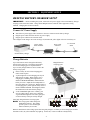
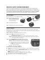
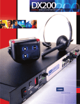
HME# 400G573
Rev −
11/1/05
DX100
Wireless Intercom
Operating Instructions
Table of Contents
INTRODUCTION ....................................................................................................................... 1
SECTION 1.
EQUIPMENT IDENTIFICATION ....................................................................................................................... 2
MAIN EQUIPMENT FEATURES ....................................................................................................................... 3
Base Station Features ........................................................................................................................................ 3
Beltpac Features ................................................................................................................................................ 3
SECTION 2.
EQUIPMENT SETUP................................................................................................................. 4
BELTPAC BATTERY CHARGER SETUP......................................................................................................... 4
Connect AC Power Supply................................................................................................................................ 4
Charge Batteries ................................................................................................................................................ 4
BASE STATION SETUP...................................................................................................................................... 5
Equipment Connections..................................................................................................................................... 5
BELTPAC SETUP AND REGISTRATION......................................................................................................... 7
Set Up Beltpacs ................................................................................................................................................. 7
Register Beltpacs ............................................................................................................................................... 7
SECTION 3.
EQUIPMENT OPERATION..................................................................................................... 9
BASE STATION OPERATION ........................................................................................................................... 9
Controls and Indicators...................................................................................................................................... 9
Low Battery Indicator........................................................................................................................................ 9
BELTPAC OPERATION.................................................................................................................................... 10
Beltpac Controls and Indicator Lights............................................................................................................. 10
Power On/Off .............................................................................................................................................. 10
Enable Hands-Free Mode ............................................................................................................................ 10
ISO (Isolate) and IC (Intercom)................................................................................................................... 10
Volume Up/Down ....................................................................................................................................... 11
Microphone Gain Adjustment ......................................................................................................................... 11
Batteries........................................................................................................................................................... 11
SECTION 4.
TROUBLESHOOTING ............................................................................................................ 12
SECTION 5.
TECHNICAL DATA................................................................................................................. 13
EQUIPMENT SPECIFICATIONS ..................................................................................................................... 13
Base Station ..................................................................................................................................................... 13
Beltpac............................................................................................................................................................. 14
DISPOSAL OF WASTE ELECTRICAL AND ELECTRONIC EQUIPMENT................................................. 15
Illustrations in this publication are approximate representations of the actual
equipment, and may not be exactly as the equipment appears.
HM Electronics, Inc. is not responsible for equipment malfunctions due to
erroneous translation of its publications from their original English version.
© 2005 HM Electronics, Inc.
The HME logo and product names are registered trademarks of HM Electronics, Inc. All rights reserved.
INFORMATION TO USER
This device complies with Part 15 of the FCC Rules. Operation is subject to the following two conditions: (1) This device may
not cause harmful interference, and (2) This device must accept any interference received, including interference that may cause
undesired operation.
This equipment has been tested and found to comply with the limits for Class B Digital Device, pursuant to Part 15
of the FCC Rules. These limits are designed to provide reasonable protection against harmful interference in a
residential installation. This equipment generates and can radiate radio frequency energy and, if not installed and
used in accordance with the instructions, may cause harmful interference to radio communications. However, there
is no guarantee that interference will not occur in a particular installation. If this equipment does cause harmful
interference to radio or television reception, which can be determined by turning the equipment off and on, the user is
encouraged to try to correct the interference by one or more of the following measures.
• Reorient or relocate the receiving antenna
• Increase the separation between the equipment and receiver
• Connect the equipment into an outlet on a circuit different from that to which the receiver is connected
• Consult the dealer or an experienced radio/TV technician for help
Any changes or modifications not expressly approved by the party responsible for compliance could void the user’s
authority to operate the equipment.
MANDATORY SAFETY INSTRUCTIONS
FOR INSTALLERS AND USERS
Use only manufacturer or dealer supplied antennas.
The Federal Communications Commission has adopted a safety standard for human exposure to RF (Radio Frequency)
energy, which is below the OSHA (Occupational Safety and Health Act) limits.
The term “IC:” before the certification/registration number only signifies that the Industry Canada technical specifications
were met.
Base Station Antenna minimum safe distance: 7.9 inches (20 cm) at 100% duty cycle.
Base Station Antenna gain: This device has been designed to operate with an antenna having a maximum gain of up to
2dBi.
Antenna mounting: The antenna(s) used for the base transmitter must be installed to provide a separation distance of at
least 7.9 inches (20 cm) from all persons and must not be co-located or operating in conjunction with any other antenna or
transmitter.
Antenna substitution: Do not substitute any antenna for the one supplied by the manufacturer or radio dealer. You may
be exposing person or persons to excess radio frequency radiation. You may contact your radio dealer or the manufacturer
for further instructions.
WARNING: Maintain a separation distance from the base station transmit antenna to a person(s) of at least 7.9 inches (20
cm) at 100% duty cycle.
You, as the qualified end-user of this radio device must control the exposure conditions of bystanders to ensure the
minimum separation distance (above) is maintained between the antenna and nearby persons for satisfying RF exposure
compliance. The operation of this transmitter must satisfy the requirements of Occupational/Controlled Exposure
Environment, for work-related use. Transmit only when person(s) are at least the minimum distance from the properly
installed, externally mounted antenna.
Hereby, HM Electronics, Inc. declares that the DX100 is in compliance with the essential requirements and other relevant
provisions of R&TTE Directive 1999/5/EC.
This product operates in the 2400 to 2483.5 MHz frequency range. The use of this frequency range is not yet harmonized
between all countries. Some countries may restrict the use of a portion of this band or impose other restriction relating to power
level or use. You should contact your Spectrum authority to determine possible restrictions.
LIMITED WARRANTY
HM Electronics, Inc. (“HME”) warrants the DX100 for a period of two (2) years* from the date of purchase
against defects in materials or workmanship provided it was purchased from an authorized dealer. During the
warranty period, defective HME Products will be repaired without charge for parts and labor. Simply return the
defective HME Product with your sales slip as proof of the date of purchase. If a defective HME Product is
returned prepaid to HME or an authorized HME service center, it will be repaired and returned prepaid.
Replacement of nonconforming goods and repair of defective HME Products are the sole and exclusive remedies
available under this warranty.
This warranty shall be void if (a) the HME Products have been tampered with, neglected, modified, abused or
misused; (b) anyone other than HME employees or authorized HME service representatives provide service on or
to the HME Products; or (c) the serial numbers are not intact.
THIS WARRANTY COVERS HME PRODUCTS, AND IS NOT EXTENDED TO ASSOCIATED NON-HME
PRODUCTS OR ACCESSORIES, OR ANY DAMAGE TO HME PRODUCTS CAUSED BY SUCH NONHME PRODUCTS OR ACCESSORIES. IN NO EVENT WILL HME BE LIABLE FOR INCIDENTAL OR
CONSEQUENTIAL DAMAGES, OR LOSS OF PROFITS ARISING FROM THE USE OF OR INABILITY TO
USE ANY HME PRODUCTS, OR FROM ACCIDENTS OR ACTS OF GOD.
HME MAKES NO WARRANTIES, EXPRESS OR IMPLIED, INCLUDING WARRANTIES OF
MERCHANTABILITY AND FITNESS FOR A PARTICULAR PURPOSE, WITH RESPECT TO HME
PRODUCTS EXCEPT AS SPECIFICALLY SET FORTH ABOVE.
This warranty is provided to the original purchaser of the HME Products described on this packing list and is nontransferable without the written permission of HME.
RETURN POLICY:
ALL SALES FINAL. No returns will be accepted (except for nonconforming goods as specified above) unless
HME authorizes such return and unless such return occurs within 90 days of receipt. A 15% restocking charge
will be assessed on all such authorized returns. Authorized returns must be freight prepaid and shall include an
authorization number noted on the outside of the package. Such authorization number will be provided by HME at
the time it authorizes such return. All freight sent collect and packages without an authorization number will be
refused and returned to sender.
* Exceptions: The BAT40 and BAT850 Batteries and the HS14, HS14D and HS20-3 Headsets are
warranted for one year. The HS4-3 Earpiece is warranted for 90 days.
SECTION 1. INTRODUCTION
The DX100 provides private, secure communication. Each base station can have up to fifteen Beltpacs
“registered” to it. Four of the fifteen Beltpacs can transmit at the same time. Beltpacs can be used either in the
push-to-talk or hands-free mode. The base station operator can stop any Beltpac from transmitting.
The base station can be operated using standard AC electricity, an external DC power source or six AA
batteries. A power supply, cable and a battery sled are included with the base station.
This is an example of a typical theatrical application. A variety of other uses for the DX100 are possible.
1
EQUIPMENT IDENTIFICATION
The following equipment is standard with the DX100 Wireless Intercom System.
As you unpack the equipment, check the packing list to be sure you received all items listed.
Base Station Battery Sled
Base Station Antennas
(2 per Base Station)
BS100 Base Station
115/230 Volt AC Power Supply
(1 per Base Station, with Power Cables)
(1 per AC40A Battery Charger, with Power Cables)
Beltpac Pouch
BP200 Beltpac
Beltpac Battery
OPTIONAL EQUIPMENT
HS4-3 Single Earpiece & Lapel Microphone
HS14 Single-Muff Medium-Weight Headset
HS14D Dual-Muff Medium-Weight Headset
HS12 Single-Earpiece Lightweight Headset
HS20-3 Dual-Earpiece Lightweight Headset
AC850 Battery Charger
AC40A Battery Charger
BAT850 Battery
XLR Headset Adapters:
MD-XLR4M Mini-DIN to 4-Pin Male
MD-XLR4F Mini-DIN to 4-Pin Female
MD-XLR5F Mini-DIN to 5-Pin Female
2
MAIN EQUIPMENT FEATURES
Base Station Features
10
9
11
12
1
2
3
4
5
6
7
8
1.
POWER indicator light
7.
UN-LATCH button
2.
RECEIVE indicator light
8.
Clear Registration “CLR REG” button
3.
RESET button
9.
Antennas
4.
REGISTRATION STATUS display
10. Power connector
5.
Power “PWR” button
11. Battery compartment cover
6.
Registration “REG” button
12. Battery compartment cover release latches
Beltpac Features
2
3
4
8
2
1
5
6
7
1.
Headset cable connector
6.
Volume-up button
2.
Beltpac indicator lights
7.
Volume-down button
3.
ISO (Isolate) button
8.
Battery
4.
IC (Intercom) button
9.
Battery release latch
5.
PWR (Power) button
3
9
SECTION 2. EQUIPMENT SETUP
BELTPAC BATTERY CHARGER SETUP
IMPORTANT! – Before installing the system, connect the AC power supply to the AC40A Battery Charger
and plug it into an electrical outlet. Charge all the Beltpac batteries while the other equipment is being
installed. Charging time is about 2.5 hours.
Connect AC Power Supply
•
•
•
Attach the AC power supply cable connector to the screw connector on the battery charger.
Plug the power cable connector into the AC power supply.
Plug the power cable into an electrical outlet.
The red lights on the charger will come on and go off, and then the yellow lights will come on and stay on.
Power supply
cable connector
AC40A Battery Charger
Power cable
connector
To electrical
outlet
AC power supply
Charge Batteries
Up to four batteries can be charged in the battery
charger at the same time. The battery status lights
next to each charging port are explained below.
Up to six fully charged batteries can be stored in the
battery storage ports.
• Insert a battery in each of four charging ports
until it clicks in place.
• A yellow light next to each charging port stays on
while the port is empty. When a battery is in a
charging port, a flashing yellow light next to it
indicates CHARGE PENDING, which means the
battery is too hot. Adjust the room temperature or
move the charger to a cooler area. When a battery is
in a charging port, a yellow light on steady next to it
means CHARGE FAILED. If this happens, follow
the instructions on the side of battery charger.
• A red CHARGING light next to a battery port
stays on while a battery in the port is charging.
A green READY light next to a battery port goes
on when a battery in the port is fully charged.
Charged batteries
in storage ports
Empty
charging ports
Battery in
charging port
Store fully charged batteries in storage ports.
NOTE: The storage ports neither charge nor
maintain the batteries. They simply
provide a place to store the charged
batteries until they are needed.
Batteries should not be left in charge ports after being fully charged. If a battery is left in a charge port for more
than three weeks, the yellow indicator may light up. In this case, it does not indicate a faulty battery.
4
BASE STATION SETUP
Locate the two base station antennas and the AC power adapter and power cable received with the base station,
and connect them to the base station as described below.
Equipment Connections
Antenna
connectors
Step 1. Connect the two enclosed
antennas to the antenna
connectors on the top and right
side of the base station, shown to
the right. Position the antennas
at right angles to each other.
The illustration below shows one
possible arrangement. Turn the
sleeve on each of the antenna
connectors clockwise to tighten
the antennas securely in position.
Step 2. Note which of the following applies to you.
•
If using the DX100 with AC power ⎯ Plug the connector at the end of the AC power supply
cord into the power connector on top of the base station. Turn the sleeve on the cable connector
clockwise to secure it to the base station. Plug the large female connector at one end of the AC
power cord into the power supply. Plug the other end of the AC power cord into an electrical outlet.
Power cable
connector
AC power supply
Sleeve
Power
cord
Antenna
Power
connector
Sleeves
Antenna
POWER
light
PWR button
Having a fully charged (or new) battery in its battery compartment when operating the DX100 with
AC or external DC power can prevent interruption of communication during a power outage, as the
DX100 base will automatically switch to battery power.
5
•
If using the DX100 with battery power ⎯ Press in and up on the two battery cover release
latches to lift the cover and open the battery compartment.
Battery cover
release latches
(Push latches in
direction of arrows
and flip lid up.)
Insert six AA batteries into the battery sled, in the positions shown inside the sled, and install the
sled in the battery compartment as shown below. An HME BAT850 Rechargeable Battery may be
used instead.
Battery sled
with batteries
Close the battery compartment by pressing its cover down until both latches snap in place.
NOTE: Pressing down on the cover next to both of the latches at the same time will assure its
proper closing.
•
If using the DX100 with an external DC power source ⎯ We recommend that you purchase a
power cord such as the Radio Shack 12VDC, 5A cigarette lighter power adapter, PN 270-1558.
Follow the manufacturer’s instructions to connect the external DC power source to the power
connector on top of the DX100. Any power supply used with the DX100 should be rated at least
12VDC, 500mA.
Having a fully charged (or new) battery in its battery compartment when operating the DX100 with
AC or external DC power can prevent interruption of communication during a power outage, as the
DX100 base will automatically switch to battery power.
6
BELTPAC SETUP AND REGISTRATION
The first time you operate the DX100 system, you must register each Beltpac for use with a specific base
station. The base station will then recognize all registered Beltpacs when their power is on, and will know the
difference between them and other electronic equipment operating on the same frequencies. If a Beltpac is added
or replaced later, the new one must be registered and the old one remains in memory. A maximum of 15 Beltpacs
can be registered to a DX100 base station at one time. After 15 Beltpacs have been registered, you will have to
clear all current registrations before registering any additional Beltpacs. Follow the instructions below.
Set Up Beltpacs
Before registering them, set up all Beltpacs as follows.
Step 1. Insert a fully charged battery in the
Beltpac, with the metal contacts on
the end of the battery inserted first.
Press it in until it snaps.
Step 2
Step 3
Step 1
Step 2. Place the Beltpac in the pouch.
Step 3. Plug the headset cable connector into the Beltpac.
Register Beltpacs
Beltpacs must be within 6 feet (1.83 meters) of the base station while you are registering them. Be certain the
base station power is on, and each Beltpac you are going to register is turned off before you begin. Beltpacs that
are already registered can be on or off.
Step 1. Put the headset, of the Beltpac being registered, on your head.
Step 2. Press the REG (registration) button on the base station.
•
The REGISTRATION STATUS display on the base station will show a small “o” for open.
NOTE: If you wait too long before going on to Step 3, the base station will go out of the registration
mode and you will have to repeat Step 2.
Step 3. Press and hold the ISO button on the Beltpac while you press and
release the PWR (power) button to turn the unit on, then release the
ISO button. This will cause the Beltpac to enter the registration mode.
•
The two power lights at the corners of the Beltpac near the IC
and ISO buttons will begin blinking red, then will blink green
two or three times and go off.
• Wait! There may be a short delay.
If registration is successfully completed:
•
•
•
•
A voice message in the headset will say “Power on, Beltpac #, Version #, Begin registration, Registration
complete, …”
After a delay of up to 15 seconds, the REGISTRATION STATUS display will show the ID number assigned
to this Beltpac for about 10 seconds.
NOTE: ID numbers are assigned sequentially as 0 thru 9, A, b, C, d and E.
The power light on the Beltpac, next to the IC button, will remain on steady green.
Repeat Steps 1 to 3 above for each Beltpac to be registered.
7
If registration failed:
•
•
A voice message in the headset will say “Power on, Beltpac #, Version #, Begin registration, …” Both
power lights on the Beltpac will be blinking red, and there may be a delay of up to 90 seconds before you
hear “Registration failed.”
Press the RESET button on the base station. When the REGISTRATION STATUS display becomes
blank, press the REG button on the base station and register the Beltpac again. If registration fails again,
call your dealer for assistance.
If you try to register more than 15 Beltpacs:
•
•
•
An F will appear on the REGISTRATION STATUS display on the base station and you will hear
“Registration failed” in the headset.
Clear all current registrations by pressing the CLR REG button and the RESET button at the same time.
Continue holding the CLR REG button after you release the RESET button, until the clear code “c” (lower
case) appears on the REGISTRATION STATUS display.
Register all active Beltpacs, one at a time. Previously registered Beltpacs must be re-registered.
8
SECTION 3. EQUIPMENT OPERATION
BASE STATION OPERATION
Controls and Indicators
•
POWER indicator light
Lights red when power is on. Blinks every 8 – 10
seconds when the battery is running low.
•
RECEIVE indicator light
Lights green when Beltpacs are transmitting.
•
RESET button
Press to reset all communication links, or press together
with the CLR REG button to clear all Beltpac
registrations.
•
REGISTRATION STATUS display
Displays “8” briefly when base station power is turned
on. Indicates status as you register each Beltpac. See
pages 7 and 8.
•
Power “PWR” button
Press and release to turn the DX100 power on. Press and hold for 2 seconds to turn power off.
•
Registration “REG” button
Use this button to register each Beltpac used with the DX100. See pages 7 and 8.
•
UN-LATCH button
Use this button to unlatch all Beltpac transmitters. Users can configure their Beltpacs to “latch” on,
in order to talk and listen to each other. Base station operators can use the UN-LATCH button to stop
Beltpac conversations. Also, if a Beltpac user takes a Beltpac off and leaves it “latched on” in an unknown
location, sounds from the area where it is left are picked up by its microphone and transmitted to other
Beltpac users. This distraction can be stopped by pressing the UN-LATCH button on the base station.
•
Clear Registration “CLR REG” button
Use this button to clear Beltpac registrations when needed. See page 8.
Low Battery Indicator
When the DX100 base station battery power is low, repeating beeps will be heard in the Beltpac headset and the
POWER light on the base station will be blinking red. When this happens, replace the batteries in the base
station immediately with ones that are new or fully charged, as instructed on page 6.
NOTE: Battery life varies with the type of batteries used. With the HME BAT850 (NimH) battery, up to 10
hours can be expected.
9
BELTPAC OPERATION
Beltpac Controls and Indicator Lights
The Beltpac control buttons have a snap action. They will activate
when pressed firmly. Use your fingertips, not your fingernails, to
press the buttons.
Power On/Off
•
Power On – Press and release the PWR (power) button.
A voice message in the earpiece will say “power on,” and the
red lights at the corners of the IC and ISO buttons will go on.
After a short time, one light will go off and the other will change
to green, indicating the Beltpac is ready for use.
The REGISTRATION STATUS indicator on the base station will
momentarily indicate the ID of the Beltpac.
• Power Off – Press and hold the PWR button for approximately two seconds.
A voice message in the earpiece will say “power off,” and the green light will go off.
NOTE: While a Beltpac is transmitting, the appropriate green light will be flashing, depending on whether the
IC or ISO mode is active. If a Beltpac is ready, but not transmitting, the green light will be on steady.
Enable Hands-Free Mode
•
Push-To-Talk (PTT) Mode Setting – To set the Beltpac for PTT communication, with the
power off, press and hold the volume-down T and ISO buttons while you press and release the PWR
(power) button. You will hear “Hands-free off” in the headset earpiece. Press and hold the IC or ISO
button while talking.
• Hands-Free (HF) Mode Setting – To set the Beltpac for HF communication, with the power off,
press and hold the volume-up S and ISO buttons while you press and release the PWR (power)
button. You will hear “Hands-free on” in your headset earpiece. When set up for hands-free
communication, the Beltpac can be operated in either HF or PTT.
NOTE: The above settings are saved in memory and only need to be repeated when you want to change between
HF and PTT modes. When changing modes, if both power lights begin blinking, turn the Beltpac off
and begin again. Hands-free and PTT mode settings affect both IC and ISO. Individual adjustment is
not possible.
ISO (Isolate) and IC (Intercom)
Use either button to communicate with other Beltpac users.
• Push-To-Talk (PTT) Mode Operation – press and hold the IC or ISO button while talking.
In PTT operation, audio will be transmitted only while you are pressing the IC or ISO button.
• Hands-Free (HF) Mode Operation – Quickly press and release the IC or ISO button to “latch”
the transmitter on. Talk and listen, as in a normal telephone conversation. Press and release the IC or
ISO button again to “unlatch,” to end the conversation. If either button is held down for more than a
half second, the Beltpac will function as PTT. All Beltpacs can be unlatched by the base station
operator, by pressing the UNLATCH button on the base station.
NOTE: In HF mode, pressing the IC button while latched in ISO will latch on IC. Pressing the ISO button
while latched in IC will latch on ISO.
10
Volume Up/Down
•
•
Volume Up Adjustment – Each time you press and release the volume-up S button, a beep will
be heard in the earpiece as the volume increases one step. If you press and hold the volume-up button,
repeating beeps will be heard as the volume steps up to maximum. When maximum volume is
reached, “maximum” will be heard in the earpiece, and will be repeated until you release the volumeup button.
Volume Down Adjustment – Each time you press and release the volume-down T button, a
beep will be heard in the earpiece as the volume decreases one step. If you press and hold the volumedown button, repeating beeps will be heard as the volume steps down to minimum. When minimum
volume is reached, rapidly repeating beeps will be heard.
Microphone Gain Adjustment
Some users talk louder or softer than others. To allow for this, microphone gain adjustment is provided.
To increase microphone gain – Press the volume-up S button while holding down the ISO button in
the normal operating mode. The microphone gain increase can be monitored through sidetone, or preferably by
someone else on a Beltpac or at the base station.
To Decrease microphone gain – Press the volume-down T button while holding down the ISO button
in the normal operating mode. The microphone gain decrease can be monitored through sidetone, or preferably
by someone else on a Beltpac or at the base station.
NOTE: You will hear “Maximum” if you attempt to go higher than maximum microphone gain.
You will hear beeps if you attempt to go lower than minimum microphone gain.
Microphone gain will be saved in non-volatile memory and does not require readjustment each time
the power is turned on.
Batteries
Change Beltpac Batteries
Battery
When a Beltpac battery becomes weak, a voice in
the earpiece will say “Change battery.” When this
happens, take the Beltpac out of its pouch and
remove its battery. Slide the arrow-shaped batteryrelease latch in the direction of the arrow. Pull up
on the end of the battery near the battery-release
latch and lift the battery out of the Beltpac, or turn
the Beltpac over and catch the battery in your hand.
Battery
release latch
When replacing a battery in the Beltpac, place the end
of the battery with the metal contacts into the battery
holder on the Beltpac, in the same position as the
battery you removed. Press the top of the battery
carefully into the battery holder until it snaps in place
under the battery-release latch.
Change Base Station Batteries
When a base station battery becomes weak, repeating beeps will be heard in the Beltpac headset and the
POWER light on the base station will be blinking red. When this happens, replace the batteries in the base
station with new or fully charged batteries as instructed on page 6.
11
SECTION 4. TROUBLESHOOTING
If you are unable to correct any of the problems described below, contact your dealer for assistance.
•
Red light on base station does not come on.
Be certain power cords are properly connected to base station, power supply and electrical outlet.
If battery operated, be certain six AA batteries are inserted in the indicated positions in the battery sled, and
the sled is installed in the base station. See page 6.
•
Beltpac power lights do not turn green and “out of range” is heard in the headset.
Be certain your base station power is on. Turn the Beltpac and base station power on and off.
You may be too far from the base station. The range varies with each location’s layout.
If you have more than one base station, be sure the Beltpac is registered to the base station it is being used
with. If you are not sure, re-register it.
•
When trying to register, it keeps saying registration failed.
Refer to “If registration failed” on page 8, and repeat the registration procedure.
•
Others cannot hear me when I talk.
Be certain the headset is securely connected to the Beltpac, that you are pressing the IC or ISO button on
the Beltpac, or the microphone gain adjust is turned up to the required level. See page 12.
2400MHz cordless telephone interference —
If there is a 2400MHz cordless telephone nearby, interference may occur. However, because the DX100
is a frequency-hopping system, this problem is unlikely. If it does occur, changing frequencies on the
telephone may alleviate the problem. If not, move the phone as far as practical from the base station, or use
another type phone.
In the event of an electrical power outage —
such as from a lightning storm or power generator failure, if you experience problems with your HME
equipment after the electricity comes on again, unplug the AC power supplies from their electrical outlets,
remove any batteries and wait 15 seconds, then plug them back in.
12
SECTION 5. TECHNICAL DATA
EQUIPMENT SPECIFICATIONS
Base Station
GENERAL ⎯
Frequency Range:
Frequency Response:
Power Requirements:
Temperature Range:
Size:
Weight:
# of Beltpacs per Base:
Front Panel Controls:
Front Panel Indicators:
Antenna Type:
System Distortion:
Communication Security:
Splash Resistant:
2400 – 2483.5 MHz
200 Hz to 3.5 kHz
100-240VAC, 50-60Hz or 12-14VDC
32-122°F (0-50°C)
10.2” x 6.45” x 3.33” (1-RU) (25.91 x 16.38 x 8.46 cm)
2.35 lbs. (1.07 kg) maximum
15 can be registered
Any 4 can have simultaneous full-duplex communication at one time.
Others would be listen-only until a channel becomes available.
Power, Register Beltpac, Reset, Unlatch and Clear Registration buttons
Registration Status display, Power and Receive LEDs
External ½ -wave dipole (R-TNC connector)
RX/TX horizontal/vertical diversity
<2%
64-bit encryption dual-slot diversity
IEC529 IP Code 4 (under battery operation only)
TRANSMITTER ⎯
Type:
Transmit Power:
Modulation Type:
Frequency Stability:
Harmonics/Spurious:
Frequency hopping, spread spectrum
100mW burst
Gaussian filtered FSK, TDM
13 ppm
Exceeds FCC and ETSI specifications over temperature
RECEIVER ⎯
Type:
RF Sensitivity:
Frequency Stability:
Distortion:
Frequency hopping, spread spectrum
<−90dBm w 10-3 BER
13 ppm
<2%
13
Beltpac
GENERAL ⎯
Frequency Range:
Antenna Type:
Frequency Response:
Battery Requirements:
Battery Life:
Temperature Range:
Weight:
Headset Connector:
Mic Input:
Headset Output:
Controls:
Indicators:
Communication Security:
System Distortion:
2400 MHz – 2483.5 MHz
Internal, horizontal/vertical diversity
200 Hz to 3.5 kHz
3.6V lithium ion
Up to 20 hours
32-122°F (0-50°C)
7.4 oz (0.21 kg) with battery and pouch
4-pin, mini-DIN
Electret microphone
160mW into 32Ω
Power, Volume-up S, Volume-down T, IC and ISO buttons
Dual-color LEDs (red/green)
64-bit encryption
<2%
TRANSMITTER ⎯
Type:
Transmit Power:
Transmission Modes:
Modulation Type:
Frequency Stability:
Harmonics/Spurious:
Frequency hopping, spread spectrum
100mW burst
Momentary or latch
Gaussian filtered FSK, TDM
13 ppm
Exceeds FCC and ETSI specifications
RECEIVER ⎯
Type:
RF Sensitivity:
Frequency Stability:
Distortion:
Frequency hopping, spread spectrum
<−90dBm w 10-3 BER
13 ppm
<2%
14
DISPOSAL OF WASTE ELECTRICAL AND ELECTRONIC EQUIPMENT
IMPORTANT!
Waste Electrical and Electronic Equipment (WEEE)
The European Union (EU) WEEE Directive (2002/96/EC) places an obligation on producers (manufacturers,
distributors and/or retailers) to take-back electronic products at the end of their useful life. The WEEE
Directive covers most HME products being sold into the EU as of August 13, 2005. Manufacturers, distributors
and retailers are obliged to finance the costs of recovery from municipal collection points, reuse, and recycling
of specified percentages per the WEEE requirements.
Instructions for Disposal of WEEE by Users in the European Union
The symbol shown below is on the product or on its packaging which indicates that this product was put on the
market after August 13, 2005 and must not be disposed of with other waste. Instead, it is the user’s
responsibility to dispose of the user’s waste equipment by handing it over to a designated collection point for
the recycling of WEEE. The separate collection and recycling of waste equipment at the time of disposal will
help to conserve natural resources and ensure that it is recycled in a manner that protects human health and the
environment. For more information about where you can drop off your waste equipment for recycling, please
contact your local authority, your household waste disposal service or the seller from whom you purchased the
product.
15