Download PRO850 - Clear-Com

Transcript
HME# 400G520
Rev F
8/1/06
PRO850
Wireless Intercom
Operating Instructions
Base Station Version A.2.0x
Table of Contents
SECTION 1. INTRODUCTION ....................................................................................................................1
EQUIPMENT FEATURES................................................................................................................................2
Base Station Front Panel Features ..................................................................................................................2
Base Station Rear Panel Features ...................................................................................................................2
Beltpac Top Panel Features ............................................................................................................................3
Beltpac Bottom Panel Features.......................................................................................................................3
BLOCK DIAGRAMS ........................................................................................................................................4
Base Station....................................................................................................................................................4
Beltpac............................................................................................................................................................4
EQUIPMENT SPECIFICATIONS ....................................................................................................................5
Base Station....................................................................................................................................................5
Beltpac............................................................................................................................................................6
Factory Defined Frequencies..........................................................................................................................7
Frequency Plan ...............................................................................................................................................8
SECTION 2. EQUIPMENT SETUP..............................................................................................................9
BASE STATION SETUP...................................................................................................................................9
SECTION 3. PRO850 OPERATION..........................................................................................................11
BASE STATION OPERATION ......................................................................................................................11
Uses of Front Panel Controls, Indicators and Connectors ............................................................................11
Display Screen Navigation ...........................................................................................................................12
Display Screen Functions and System Settings............................................................................................13
Status Displays .........................................................................................................................................13
Monitor Displays ......................................................................................................................................14
Base Configuration Settings .....................................................................................................................15
Beltpac Configuration Settings.................................................................................................................20
Saving and Loading Configurations .........................................................................................................23
Advanced Configuration Settings.............................................................................................................24
Information Displays ................................................................................................................................28
Diagnostic Tests .......................................................................................................................................29
ADVANCED CONFIGURATION ..................................................................................................................30
Auxiliary Input and Output Functions:.........................................................................................................30
Single Transmitter Two-Channel Operation.................................................................................................30
IFB Transmitter Operation .......................................................................................................................30
Cascading Multiple Base Stations ................................................................................................................31
Aux Distributed Set Up ............................................................................................................................31
2-Wire Distributed Set Up........................................................................................................................31
Common Configuration............................................................................................................................32
Alert Relay Operation...................................................................................................................................32
BELTPAC OPERATION.................................................................................................................................33
Controls and Buttons ....................................................................................................................................33
Indicator Lights ............................................................................................................................................34
Connectors and Adjustment..........................................................................................................................35
Batteries........................................................................................................................................................36
Infrared Window ..........................................................................................................................................36
Dual-Receiver Operation..............................................................................................................................36
Troubleshooting............................................................................................................................................37
SECTION 4. PRO850 SYSTEM SOFTWARE...........................................................................................38
PC850 Installation ........................................................................................................................................38
PC850 Operation ..........................................................................................................................................39
SECTION 5. PDA850 Installation................................................................................................................41
PDA850 Installation .....................................................................................................................................41
PDA850 Operation .......................................................................................................................................41
END-USER LICENSE AGREEMENT FOR HME PRO850 SYSTEM SOFTWARE ................................42
LIMITED WARRANTY ...................................................................................................................................46
FCC LICENSING
The HME PRO850 is Type Accepted under Part 74 of the United States Federal Communications
Commission (FCC) Code of Federal Regulations governing general purpose applications. The system
requires an FCC station license if operated within the United States or its possessions. Licensing of this
equipment is the User’s responsibility. Licensability depends on the User’s classification, equipment
application and frequency selected. The user should contact the appropriate telecommunications authority
for any desired clarification.
CAUTION: Changes or modifications made by the user could void the user’s authority to operate
PRO850 equipment.
MANDATORY SAFETY INSTRUCTIONS
TO INSTALLERS AND USERS
Use only manufacturer or dealer supplied antennas.
Base Station Antenna minimum safe distance: 9.54 inches (24.24 cm) at 100% duty cycle.
Base Station Antenna gain: zero dBi referenced to a monopole.
The Federal Communications Commission has adopted a safety standard for human exposure to RF
(Radio Frequency) energy, which is below the OSHA (Occupational Safety and Health Act) limits.
Antenna mounting: The antenna supplied by the manufacturer or radio dealer must not be mounted at a
location such that during radio transmission, any person or persons can come closer than the above
indicated minimum safe distance to the antenna, i.e. 9.54 inches (24.24 cm) at 100% duty cycle.
To comply with current FCC RF exposure limits, the antenna must be installed at or exceeding the
minimum safe distance shown above, and in accordance with the requirements of the antenna
manufacturer or supplier.
Antenna substitution: Do not substitute any antenna for the one supplied or recommended by the
manufacturer or radio dealer. You may be exposing person or persons to excess radio frequency
radiation. You may contact your radio dealer or the manufacturer for further instructions.
WARNING: Maintain a separation distance from the base station transmit antenna to a person(s) of at
least 9.54 inches (24.24 cm) at 100% duty cycle.
You, as the qualified end-user of this radio device must control the exposure conditions of bystanders to
ensure the minimum separation distance (above) is maintained between the antenna and nearby persons
for satisfying RF exposure compliance. The operation of this transmitter must satisfy the requirements of
Occupational/Controlled Exposure Environment, for work-related use. Transmit only when person(s) are
at least the minimum distance from the properly installed, externally mounted antenna.
Hereby, HM Electronics, Inc. declares that the PRO850 is in compliance with the essential requirements and
other relevant provisions of EMC Directive 89/336/EEC.
Illustrations in this publication are approximate representations of the actual
equipment, and may not be exactly as the equipment appears.
HM Electronics, Inc. is not responsible for equipment malfunctions due to
erroneous translation of its publications from their original English version.
SECTION 1. INTRODUCTION
PRO850 equipment operates in the UHF band from 470 MHz to 740 MHz in 18 MHz subsets. Transmitters and
receivers operate in different, non-adjacent 18 MHz bands. Synthesized frequencies can be selected in 25 kHz
increments over each 18 MHz band, for 720 transmit and 720 different receive frequencies.
Base stations can be configured with up to four receivers and two transmitters, supporting up to four Beltpacs in fulltime transmit, full-duplex operation. Two or three base stations interconnected can support up to twelve Beltpacs
operating at once. The channel lockout feature supports several Beltpacs sharing the same frequency. In this mode,
one Beltpac user on a shared frequency can transmit at a time. If another user is already transmitting on that frequency,
a “busy” signal will be heard. A maximum of sixteen Beltpacs can be used with a system (one to three base stations).
A feature can be selected that scans through all available intermodulation-free frequency groups to automatically
configure the system for the best available set of frequencies. Specified frequencies can be saved for quick recall.
The PRO850 can be configured for fixed power output levels or automated output power control. With the
automated feature selected, the PRO850 senses how far a Beltpac is from the base station and automatically
determines at what power level the Beltpac should be operating, eliminating base station receiver overload and
increasing Beltpac battery life.
Two hardwired intercom channels provide simultaneous 2-wire and 4-wire operation.
The base station headset interface automatically detects and accommodates dynamic or electret microphones.
It provides direct access to intercom channels 1 and 2, Beltpacs only or all channels.
Any Beltpac button can be configured to activate the base paging relay and, at the same time, audio is routed to the
paging output.
The base can be configured to initiate an alert for various conditions, including low battery condition or button
press from a Beltpac.
The PRO850 is fully compatible with RTS® and Clear-Com® hard-wired intercom systems.
With the provided PC850 software, the base station and Beltpacs can be configured on a PC, and configuration
settings can be saved to files. An RS-232 serial port on the rear panel of the base station provides PC interface
capability. Beltpacs can also be configured using a Palm-OS PDA with the optional PDA850 software.
The base station can operate from a standard 12-14VDC power source or from an external DC source such as a
vehicle electrical system for mobile operation.
1
EQUIPMENT FEATURES
Base Station Front Panel Features
1
2
3 4 5
6
7 8
9
10
11 12 13 14
1.
POWER switch
8.
2.
BELTPAC CONFIGuration connector
(RJ10 telephone handset cable connector)
CANCEL button (backs out of menus or
cancels operation)
9.
Display screen
3.
15
10. Multi-function knob (headset volume control;
adjustment for specific menu selections)
WIRED STATUS lights
CH1 = Channel 1 intercom status
CH2 = Channel 2 intercom status
AUX = ISO+ mode
11. Local headset function lights
12. Local headset function select switch
4.
RECEIVER QUICK MENU buttons
5.
RECEIVER STATUS lights
6.
Arrow buttons (move curser around on menu)
7.
ENTER button (selects function or setting)
13. Local headset TALK indicator light
14. Local headset TALK switch
15. Local headset connector
Base Station Rear Panel Features
16
17 18
19 20
21
22
23 24
25
26
27
28
29
30 31 32 33
17. 9-pin RS-232 computer connector
25. Channel 2 RJ45 4-wire intercom interface
connector
18. RS-422 interface
(for connecting two or more bases together)
26. Auxiliary input connector
(accepts XLR plug or standard phone plug)
19. Channel 1 null adjustment
27. Auxiliary output connector
20. Channel 1 2-wire intercom interface connector
28. Paging output connector
21. Clear-Com/RTS select button
29. 12-14VDC power jack
22. Channel 2 2-wire intercom interface connector
30. Page relay connector
23. Channel 2 null adjustment
31. Alert relay connector
24. Channel 1 RJ45 4-wire intercom interface
connector
32. Transmitter antenna connector
16. Receiver antenna connector
33. Grounding screw
2
Beltpac Top Panel Features
1
2
3 4 5
6
7
8 9 10 11 12
1.
Master power/volume control
7.
“D” function light
2.
“A” button
8.
“B” light – indicates Channel 2 active
3.
Power and battery condition indicator
9.
“D” button
4.
“C” button
10. Transmit light – indicates transmitter on
5.
“A” light – indicates Channel 1 active
11. “B” button
6.
“C” function light
12. Auxiliary volume control
Beltpac Bottom Panel Features
13
14 15 16
17 18 19
20
13. Headset connector
17. Remote configuration connector
14. Transmitter antenna connector
18. Microphone gain adjustment
15. Battery compartment cover
19. Auxiliary input connector
16. Battery cover thumb grip
20. Receiver antenna connector
3
BLOCK DIAGRAMS
Base Station
Beltpac
4
EQUIPMENT SPECIFICATIONS
Base Station
GENERAL ⎯
Frequency Range:
Frequency Response:
Power Requirements:
Temperature Range:
Size:
Weight:
# of Receivers:
# of Transmitters:
4-Wire I/O:
2-Wire I/O:
Auxiliary Input:
Auxiliary Output:
Paging Output:
Page & Alert Relay:
Beltpac Interface:
PC Interface:
External Control Interface:
Headset Connector:
Mic Input:
Headset Output:
Front Panel Controls:
Front Panel Indicators:
Rear Panel Controls:
TRANSMITTER ⎯
Type:
Transmit Power:
Modulation Type:
Deviation:
Occupied Bandwidth:
Frequency Stability:
Harmonics/Spurious:
Antenna Type:
470-608 MHz, 614-740 MHz in 18 MHz TX and RX bands
50 Hz to 10 kHz
100-240VAC, 50-60Hz or 12-14VDC
32-122°F (0-50°C)
19” x 1.72” x 11.5” (1-RU) (48.26 x 4.37 x 29.21 cm)
<11 lbs. (4.99 kg maximum)
1 to 4, configurable
0 to 2, configurable
RJ45, 600Ω balanced, level adjustable, simultaneous operation with 2-wire
XLR-3F, externally-switchable RTS® or Clear-Com® mode, 200Ω,
level adjustable, null adjustable
XLR-3F/¼” (6.35 mm) combo jack, 600Ω balanced, level adjustable
XLR-3M, 600Ω balanced, level adjustable
2 four-pin Molex, 60W switching capacity (2A @ 30VDC)
RJ10, RS-232
DB9, RS-232, 38400 baud
RJ45, RS-422
XLR-4M
Optional field-installable XLR-5F
pin 1 = mic-lo
pin 1 = mic-lo
pin 2 = mic-hi
pin 2 = mic-hi
pin 3 = ear-lo
pin 3 = common
pin 4 = ear-hi
pin 4 = ear-left
pin 5 = ear-right
Auto-detect, low impedance dynamic or electret microphone
Stereo – 160mW per side
Mono – >200mW into 50Ω
Power Switch
Up, Down, Left, Right, Enter & Cancel Menu Buttons
Receiver Quick-Menu Buttons
Rotary knob for adjustments
Headset channel select & PTT
Graphic LCD, 4 Receiver Status LEDs, 3 Intercom Status LEDs,
3 Headset channel select LEDs, Headset PTT LED
2-wire channel line null
RTS®/Clear-Com® mode switch
720 synthesized, 25 kHz channel steps
240, 100, 10 or 1 mW
FM
50 kHz
190 kHz maximum
10 ppm
Exceeds FCC specifications
¼-wave whip (supplied) or external (BNC connector)
5
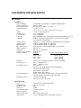
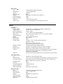
RECEIVER ⎯
Type:
RF Sensitivity:
Squelch:
Image Rejection:
Squelch:
Squelch Quieting:
Frequency Stability:
Distortion:
Antenna Type:
720 synthesized, 25 kHz channel steps
<1µV for 20dB SINAD
Adjustable
60dB
Data channel coded plus carrier signal level
90dB
10 ppm
<1% at maximum deviation
¼-wave whip (supplied) or external (BNC connector)
Beltpac
GENERAL ⎯
Frequency Range:
Antenna Type:
Frequency Response:
Battery Requirements:
Battery Life:
Temperature Range:
Weight:
Base Interface:
PDA Interface:
Auxiliary Input:
Headset Connector:
Mic Input:
Headset Output:
Controls:
Indicators:
TRANSMITTER ⎯
Type:
Transmit Power:
Transmission Modes:
Modulation Type:
Deviation:
Occupied Bandwidth:
Frequency Stability:
Harmonics/Spurious:
RECEIVER ⎯
Type:
RF Sensitivity:
Image Rejection:
Squelch:
Squelch Quieting:
Frequency Stability:
Distortion:
470-608 MHz, 614-740 MHz in 18 MHz TX and RX bands
Flexible ¼-wave, field-replaceable
50 Hz to 10 kHz
6 “AA” Alkaline Cells (optional NiMH)
PTE − Up to 9 hours (alkaline), PTT − Up to 15 hours (alkaline)
32-122°F (0-50°C)
16 oz (.454 kg) with batteries
RJ10, RS-232
IrDA
Connector: 1/8” (3.18 mm) miniature phone jack
Impedance: 10kΩ
Receive Level: 100mV minimum
Overrides optional 2nd receiver if installed
XLR-4M, optional field-installable XLR-5F
Auto-detect, low impedance dynamic or electret microphone
200mW @ 1% THD into 50Ω, capable of driving 8-400Ω
Main Volume Control with power switch and push-to-mute, 2nd RCVR/Ext.
Volume Control with push-to-mute, 4 mode/function switches
Microphone gain adjustment
Power/low battery LED, Transmit LED, 2 channel LEDs, 2 function LEDs
Synthesized, 720 25 kHz channel steps
100, 50, 10 or 1 mW configurable for fixed output or automatic power control
Push-to-talk (PTT), push-to-talk-shared (PTS), or push-to-enable (PTE)
May be configured for momentary or latch mode
FM
50 kHz
190 kHz maximum
10 ppm
Exceeds FCC specifications
Synthesized, 720 25 kHz channel steps
<1µV for 20dB SINAD
60dB
Adjustable carrier signal level
80dB
10 ppm
<1% at maximum deviation
6
Factory Defined Frequencies
Band A
Beltpac TX / Base RX
Band 2
Base TX / Beltpac RX
Band C
Beltpac TX / Base RX
Band 4
Base TX / Beltpac RX
Group/
Channel
Freq. (MHz)
Group/
Channel
Freq. (MHz)
Group/
Channel
Freq. (MHz)
Group/
Channel
Freq. (MHz)
S1
651.250
P1
508.250
S1
687.250
P1
544.250
P1
651.375
S1
508.500
P1
687.375
S1
544.500
T1
651.500
T1
509.250
T1
687.500
T1
545.250
S2
651.875
P2
509.750
S2
687.875
P2
545.750
P2
652.000
S2
514.250
P2
688.000
S2
550.250
T2
652.125
T2
514.500
T2
688.125
T2
550.500
S3
653.000
P3
515.250
S3
689.000
P3
551.250
P3
653.125
S3
515.750
P3
689.125
S3
551.750
T3
653.250
T3
520.250
T3
689.250
T3
556.250
S4
654.875
P4
520.500
S4
690.875
P4
556.500
691.000
S4
557.250
T4
557.750
P4
655.000
S4
521.250
P4
T4
655.125
T4
521.750
T4
691.125
S5
655.250
S5
691.250
P5
655.375
P5
691.375
T5
655.500
T5
691.500
S6
656.250
S6
692.250
P6
656.375
P6
692.375
T6
656.500
T6
692.500
S7
659.000
S7
695.000
P7
659.125
P7
695.125
T7
659.250
T7
695.250
S8
661.000
S8
697.000
P8
661.125
P8
697.125
T8
661.250
T8
697.250
S9
663.625
S9
699.625
P9
663.750
P9
699.750
T9
663.875
T9
699.875
S10
664.125
S10
700.125
P10
664.250
P10
700.250
T10
664.375
T10
700.375
S11
664.875
S11
700.875
P11
665.000
P11
701.000
T11
665.125
T11
701.125
S12
666.500
S12
702.500
P12
666.625
P12
702.625
T12
666.750
T12
702.750
7
Frequency Plan
PRO850 frequency bands (MHz) along with US TV channel assignments.
Base and Belt-Pac use corresponding band pairs: 0 & 8, 1 & 9, 2 & A, 3 & B, 4 & C, 5 & D, 6 & E
Antenna marking colors are shown in parenthesis.
Base Transmit Bands
CH 14 CH 15 CH 16 CH 17 CH 18 CH 19 CH 20 CH 21 CH 22 CH 23 CH 24 CH 25 CH 26 CH 27 CH 28 CH 29 CH 30 CH 31 CH 32 CH 33 CH 34
BAND 0
470 MHz
BAND 1
488
BAND 2
(none — black)
506
BAND 3
524
BAND 4
(red)
542
BAND 5
560
BAND 6
578
596
Belt-Pac Transmit Bands
CH 38 CH 39 CH 40 CH 41 CH 42 CH 43 CH 44 CH 45 CH 46 CH 47 CH 48 CH 49 CH 50 CH 51 CH 52 CH 53 CH 54 CH 55 CH 56 CH 57 CH 58
BAND 8
614 MHz
BAND 9
632
BAND A
(white)
650
BAND B
668
BAND C
(yellow)
686
NOTE: Band pairs 2A and 4C are current production.
8
BAND D
704
BAND E
722
740
SECTION 2. EQUIPMENT SETUP
BASE STATION SETUP
Connect equipment and make adjustments described below to the rear panel of the base station where indicated
on this illustration.
16
17 18
19 20
21
22
23 24
25
26
27
28
29
30 31 32 33
Base station rear panel
16. RECEIVE Antenna Connector — Connect the receiver antenna to this BNC connector. The color band
(if present) around the antenna should match the color dot (if present) near the connector on the base.
17. RS-232 Interface Connector — To interface the PRO850 with a PC using a computer interconnect cable
with a 9-pin RS-232 serial interface connector, connect the cable from this connector to the PC.
18. Multiple Base Station Interface Connector — Use this RS-422 serial interface to connect Master and
Slave base stations together.
In the 2-Wire ISO+ mode, the headset connector on
the front panel of the base station is disabled from
normal headset functions and becomes available for
connection to devices other than a headset.
In the 2-Wire mode;
• If you have an RTS system, only one 2-wire cable
is needed for connecting bases. The switch on the
back panel of the base station (#21 above) must be
set for RTS TW. One cable carries both CH1 and
CH2.
• If you have a Clear-Com system, two cables are
needed for connecting base stations. The switch on
the back panel of the base station (#21 above) must
be set for CLEAR-COM.
In all multibase configurations, connect the Aux Out
from Slave 1 to the Aux In of the Master Base Station
and connect the Aux Out from Slave 2 (if present) to
the Aux In of Slave 1.
NOTE: When only one Slave will be cascaded with
a Master, a standard Ethernet crossover cable can be
used for the data connection. This is the type of
cable used to connect two computers without a hub or
router. It is available in stores.
9
19. Channel 1 Line Nulling Control — Use this adjustment to null the Channel 1, 2-wire connection when
attached to other cabled intercom devices. This control is active even if the 4-wire only mode is selected.
20. Channel 1 2-Wire Intercom Connector — Provides 3-pin female XLR connector for interfacing other
cabled intercom devices to Channel 1 on the PRO850.
NOTE: PRO850 does not provide or require 2-wire line power.
Pin 1 = Common
Clear-Com® Mode:
Pin 1 = Common
RTS® Mode:
Pin 2 = Channel 1
Pin 2 = N/C
Pin 3 = Channel 2
Pin 3 = Channel 1
21. Clear-Com®/RTS® Select Button — In position = RTS® Mode
Out position = Clear-Com® Mode
22. Channel 2 2-Wire Intercom Connector — Provides 3-pin female XLR connector for interfacing other
cabled intercom devices to Channel 2 on the PRO850.
NOTE: PRO850 does not provide or require 2-wire line power.
RTS® Mode:
Pin 1 = Common
Clear-Com® Mode:
Pin 1 = Common
Pin 2 = Channel 1
Pin 2 = N/C
Pin 3 = Channel 2
Pin 3 = Channel 2
23. Channel 2 Line Nulling Adjustment — Use this adjustment to null the Channel 2, 2-wire connection when
attached to other cabled intercom devices. This control is active even if the 4-wire only mode is selected.
24. Channel 1 RJ45 4-wire Intercom Interface Connector — Use this RJ45
connector for 600Ω balanced interface of PRO850 Channel 1 with other
cabled intercoms. Pin designations are as follows.
Pins 1, 2, 7 & 8 have no connection
Pin 3 = Intercom Out +
Pin 4 = Intercom In +
Pin 5 = Intercom In –
Pin 6 = Intercom Out –
25. Channel 2 RJ45 4-wire Intercom Interface Connector — Same as #10, but for Channel 2.
26. Auxiliary Input Connector — Use this 3-pin female XLR/standard-phone-jack connector for balanced
+20dBV maximum auxiliary audio input.
Pin 1 = Ground = Sleeve
Pin 2 = Audio + = Tip
Pin 3 = Audio – = Ring
27. Auxiliary Output Connector — Use this 3-pin male XLR connector for balanced +20dBV maximum
auxiliary audio output.
Pin 1 = Ground
Pin 2 = Audio +
Pin 3 = Audio –
28. Paging Output Connector — Use this 3-pin male XLR connector for balanced +20dBV maximum paging
audio output.
Pin 1 = Ground
Pin 2 = Audio +
Pin 3 = Audio –
29. 12-14VDC Power Jack — Use this connector for DC power input.
30. Page Relay Connector — Use this 4-pin Phoenix connector for relay closure based on Beltpac page
control. Switching capacity of the relay is 60W (2A @ 30VDC). Pin designations are as follows.
Pin 1
Pin 1 = Common
Pin 2 = Normally Closed
Pin 3 = Normally Open
Pin 4 = Ground
31. Alert Relay Connector — Use this 4-pin Phoenix connector for relay closure based on alert conditions.
Switching capacity of the relay is 60W (2A @ 30VDC). Pin designations are the same as for #16 above.
32. TRANSMIT Antenna Connector — Connect the transmitter antenna to this BNC connector. The color
band (if present) around the antenna should match the color dot (if present) near the connector on the base.
33. Grounding Screw — Tie this connector to earth ground if the chassis is not otherwise grounded.
10
SECTION 3. PRO850 OPERATION
BASE STATION OPERATION
Uses of Front Panel Controls, Indicators and Connectors
1
1.
2
3
4-5
11-15
Power Switch
Press the upper part of the switch to turn the power on. A red light on the switch will be lit when the base
station power is on. Press the lower part of the switch to turn the power off. The red light will go off.
2.
Beltpac Configuration Connector
After Beltpac configuration settings have been made in the base station, plug one end of the enclosed RJ10
interconnect cable into this connector, and plug the other end into the RMT receptacle on the bottom of a
Beltpac to upload the settings into the Beltpac. Repeat this to upload settings for each Beltpac to be used.
CAUTION: Be sure not to turn the Beltpac power off and on again while it is connected to the base
station. If this does happen, unplug the cable and cycle the Beltpac power again.
3.
Wired Status Indicator Lights
CH1 and CH2 lights:
If a 4-wire intercom channel is enabled, the respective CH1/CH2 light will blink when the PRO850 is
sending audio on that intercom line.
If a 2-wire interface channel is enabled, the respective CH1/CH2 light will be on steady when the user
is not talking. When the user is talking, the light will be on steady and blinking off.
AUX light:
The auxiliary light indicates use of the ISO+ mode. When ISO+ is on, the AUX light will be on
steady. When someone is talking on the ISO channel, the light will be on steady and blinking off.
4-5.
Receiver Status Indicators and Buttons
RECEIVER STATUS lights 1 – 4:
Steady red if the respective receiver squelch is turned down, or if it is receiving a signal (squelch is open).
Blinking amber when the respective receiver is receiving status update from a Beltpac.
Steady green when the Beltpac user is talking through the receiver.
Blinking red or green if the Beltpac being received has a low battery condition.
RECEIVER QUICK MENU buttons 1 – 4:
When pressed, squelch and audio controls for the respective receiver are provided immediately on the
display screen.
11-15. Local Headset Connector and Controls
Plug your local headset connector into the receptacle at the right end of the PRO850 front panel.
Use the SELECT button to choose communication channels CH1, CH2, CH1 and CH2 together, or ISO.
The respective indicator light above the button will remain lit for the selection you make.
Press and release the TALK button quickly to “latch on” for open communication. Press and release the
button again quickly to “latch off.”
Press and hold the TALK button for more than one second for momentary communication. In this mode,
the selected channel will remain open only as long as you are pressing the TALK button.
11
Display Screen Navigation
6-10
6-10. To navigate through PRO850 screen displays, use the W XST, ENTER and CANCEL buttons and the control
knob adjacent to the screen as follows.
WX
Use the left and right arrow buttons to move through horizontal
selections on the bar at the top of the main menu, and to move
to the left and right on advanced screens.
Main Menu
ST
Use the up and down arrow buttons to move through vertical
selections on the main menu, such as Tx, Rx and System,
and to move up and down on the screen.
The bar next to vertical selections has an indicator in it that moves up or down as you use the up and
down arrow buttons to move through selections. The indicator will move up and down the bar in
increments, from the top of the bar for the first selection to the bottom of the bar for the last selection.
NOTE: Holding an arrow button continuously will allow you to move rapidly through selections.
Currently selected items
are highlighted.
ST
WX
When a curser appears on the screen, use any of the four
arrow buttons to move it around to desired selectable items,
or to change the content of a box adjacent to the curser.
Use the ENTER button to make a selection indicated by a curser or highlighted button (e.g. Off/On), or to
advance to the next screen from a highlighted selection.
Use the CANCEL button to move back to a previous screen. Press CANCEL repeatedly to return to the main menu.
Use the control knob to adjust values selected with the curser
such as frequencies, squelch levels and auxiliary output mix levels.
Use the control knob together with the up and down arrow buttons to change numbers such as frequency
numbers, or words such as Beltpac user names in selected boxes. The arrow buttons move highlighted numbers
left and right, while the control knob changes the numbers, letters or symbols.
12
Display Screen Functions and System Settings
Status Displays
Status displays provide information indicating the status of the system, or of parts or functions of the system.
Transmitter Status:
Select transmitter 1 or 2, then press the ENTER
button to obtain the status of the selected
transmitter.
Receiver Status:
Select receiver 1 through 4, then press the
ENTER button to observe signal and tuning
levels at the selected receiver.
System Status:
Base station power supply voltages are shown.
The 12V box shows the actual input voltage
supplied to the base station. The T°C box shows
base station internal temperature in degrees Celsius.
Beltpac Status:
Select a Beltpac by the name or number shown,
then press the ENTER button to obtain its status.
Select Stop Tlk to stop a latched-on Beltpac from
transmitting.
NOTE: In Push-To-Talk (PTT) or Push-To-Enable
(PTE) modes, Beltpacs automatically update status to
the base station every 3 seconds. In Push-To-Share
(PTS) mode, Beltpacs only update status while they
are transmitting. If no transmission is received from a
Beltpac within 20 seconds, its status will be shown as
Unk (unknown). Also, if a Beltpac is out of range, or
its power is off, its status will be shown as Unk.
13
The Pwr box shows the current transmitter power
level of the selected Beltpac.
The Sig box indicates how well the Beltpac is
receiving transmission (Low, OK or High) from
the base station.
The Bat box shows battery status of the selected
Beltpac (OK, Low or Dead).
Talk Status:
Beltpac user identification is shown when Beltpac
user is pressing Talk button.
Monitor Displays
Monitor displays provide input/output levels and input level adjustments for all devices connected to the
base station.
Monitors Audio Levels at Base Station Inputs:
Select the desired input source, then move the
curser to the bar at the top of the screen. Use the
control knob to adjust the audio input level from
the selected source in 1.5dB increments.
Monitors Audio Levels at Base Station Outputs:
Use the up/down arrow button to view the output
level from the DSP of the desired output to be
monitored.
14
Base Configuration Settings
Configuration displays provide customized configuration settings for the base station and Beltpacs. They
also allow you to save your settings to a file for future access. Advanced settings are provided for output
mixing, alert signals and paging capabilities. Beltpac ID name and number settings made at the main base
station can be synchronized in added Slave base stations via the Configuration, Sync Bases display.
Base Station Transmitter Power:
Select transmitter 1 or 2, then press the ENTER
button.
At the power level box, select 1, 10, 100 or
250mW, then press the ENTER button. To
change the Off/On status of the transmitter, select
the Off or On button, then press the ENTER
button.
To enable IFB mode (only usable with dual
receiver Beltpacs), select the IFB button, then
press the ENTER button.
Base Station Transmitter Frequency:
Frequencies P1 – P4, S1 – S4 and T1 – T4 are
preset in the system and cannot be changed.
Frequencies U1 – U5 can be set by the user.
Select transmitter TX1 or TX2, then select a
frequency for that transmitter. If you select a user
frequency, U1 – U5, move the cursor to the
frequency box and use the up and down arrow
buttons together with the control knob to select a
frequency. User frequencies can be selected in
25kHz increments.
NOTE: Frequencies within the same group
(P, S or T) are compatible with each other and free
of intermodulation.
Base Station Transmitter Output Mix Levels:
Select transmitter 1 or 2, then press the ENTER
button.
Use the left arrow button to select the Tx box,
then use the control knob to adjust the transmitter
Master output level in 1.5dB increments.
Select a box next to IC1, IC2 or Aux to enable that
input in the output mix. Mic is a standard input.
Place the cursor to the left of any slider bar and use
the control knob to adjust each output level in
increments of .25dB (fine) or 2.25dB (coarse).
NOTE: See Dial Adjustment Setting (page 20) for
information on changing between fine and course.
15
Base Station Transmitter Mix Levels (continued):
Select transmitter 1 or 2, then press the ENTER
button.
Use the left arrow button to select the Tx:dB box,
then use the control knob to adjust the transmitter
output level in 1.5dB increments.
Select the box to the left of RX1 through RX4, to
continuously enable a particular receiver to the
transmitter. NOTE: Leave these boxes
unchecked for normal operation.
Place the cursor to the left of any slider box and use
the control knob to adjust each output level in
increments of .25dB (fine) or 2.25dB (coarse).
NOTE: See Dial Adjustment Setting (page 20) for
information on changing between fine and course.
Base Station Receiver Frequency:
Frequencies P1 – P4, S1 – S4 and T1 – T4 are
preset in the system and cannot be changed.
Frequencies U1 – U5 can be set by the user.
Select receiver RX1 – RX4, then select a frequency
for that receiver. If you select a user frequency, U1
– U5, move the cursor to the frequency box and use
the up and down arrow buttons together with the
control knob to select a frequency. User
frequencies can be selected in 25kHz increments.
For multiple Beltpacs to share a receiver frequency
(PTS), check the Ptt Shared box. If you select
Ptt Shared you must also set the Beltpac
transmitters to pts (See page 20).
NOTE: Frequencies within the same group
(P, S or T) are compatible with each other and free
of intermodulation.
Base Station Receiver Control:
Select a receiver and select the Off or On button
to turn it off or on. Use the up and down arrow
buttons together with the control knob to adjust
the squelch and audio levels.
NOTE: The amount of gain applied here to
receiver audio level at input of DSP will also be
shown on the Monitor Input display screen for that
receiver.
16
Base Station Configuration:
Single
Select Single: Not Dist for a single base station
without the ISO+ feature for ISO communication
only among Beltpacs.
Select Single: ISO+ for a single base station with
the ISO+ feature for ISO communication among
Beltpacs and auxiliary input and output
(Aux In/Out) connections.
Master / Slaves
If Master and Slave base stations will be used,
there can only be one Master base station, with
one or two Slaves. Select Master, Slave 1 or
Slave 2, then select the multibase wiring
configuration; 2-Wire, 2-Wire ISO+ or Aux
Dist.
NOTE: Slaves must be configured for the
same type of audio distribution as the Master.
Master ▬
In the 2-Wire ISO+ mode, Beltpacs having a
button configured for Talk Aux must transmit
on frequencies for the Master base station for
the feature to work.
Slaves ▬
In the Aux Dist mode, Beltpacs on Slave base
stations can only talk on the same channel at
once. If they try to talk on a different channel
than the user already talking, they will hear a
busy signal in their Beltpac headset.
17
Base Station Intercom Configuration:
Select intercom IC1 or IC2, then use the up and
down buttons to select what Mode the intercom is in;
OFF, 4-Wire Only or 2-Wire/4-Wire.
Select the IC Lvl box, and use the control knob to
adjust the input gain level.
NOTE: If the Mode is set to Off, the input and
output of that intercom will be off. For 2-wire, set
to “2-wire/4-wire.” Both will be active. If set for
4-wire, only 4-wire interface will be active. Even
when “4-wire only” is selected, the line null
control(s) on the rear panel must be properly
adjusted to avoid excessive retransmit levels.
Base Station Auxiliary Input Level:
Use the control knob to adjust the auxiliary input
level. Any change made here will be reflected in
the Monitor Input display for Aux Input.
Base Station Microphone Input Level:
Use the control knob to adjust the front-panel
headset microphone input level. Any change
made here will be reflected in the Monitor Input
display for the Mic Input.
18
Frequency Scan:
Connect a Beltpac to the BELTPAC CONFIG
connector on the front panel of the base station to
enable scanning of base transmit frequencies.
In this operation, the Beltpac and base station
receivers are scanned to find the cleanest group of
frequencies for the base station to transmit on, and
they are assigned to TX1 and TX2 in the base
station. Also, based on the number of receivers in
the system (up to 12), it determines the best group
of frequencies for the base station(s) to receive on.
Those frequencies are distributed (first-come,
first-served) to the Beltpacs (assuming 16 Beltpacs
will be used) as Beltpac transmit frequencies.
Beltpac receiver frequencies are always the same
as the base station TX1 and TX2 frequencies.
Beltpac frequency settings will not be operational
until they are uploaded to the Beltpacs, which
should be done after completion of Beltpac
configuration settings.
These settings will automatically be saved to File 1
as active settings for the base station until the
frequencies are scanned again. They can also be
saved to another file name for future use.
To begin frequency scanning, press the ENTER
button. A warning message will be displayed.
Press CANCEL to clear the message. Press
ENTER again to start the scan.
NOTE: In a Master/Slave configuration, always
perform frequency scans at the Master base. The
Master will automatically save its settings in File 1.
However, the Slave(s) will not. Slave settings must
be saved manually at each Slave, or with PC850.
Base Station Identifier:
Use the arrow buttons and control knob to assign
an identifying name or number of up to nine
characters to the base station.
To enable the display of the name as a screen
saver when other operations are not being
performed, check the Enable box. The base name
will be displayed a few minutes after the last
button has been pressed. Once the screen saver is
active, press Cancel to clear it.
Base Station Display Contrast Level:
Use the control knob to adjust the base station
display screen contrast level.
19
Base Station Dial Adjustment Setting:
Select Fine or Coarse for the control knob, for mix
level dial adjustments. In the Fine mode, mix
level adjustments made by the control knob occur
in 0.25dB increments. In the Coarse mode, they
occur in 2.25dB increments.
Beltpac Configuration Settings
Beltpac configuration settings are stored in the base station, but do not become effective until they are
uploaded into individual Beltpacs. In a Master/Slave configuration, all Beltpac settings changes must be
made at the Master. Uploading is also done at the Master. Be sure to SYNC bases after making settings
changes at the Master.
Beltpac Transmitter Power:
Select the desired Beltpac and its transmitter
power level (1, 10, 50 or 100mW).
Select the transmit mode and press ENTER.
In the auto mode, transmitter power will be automatically controlled by the base station, changing
between 1 and the specified maximum. In the
fixed mode, the setting you select will not change.
If you select ptt, the Beltpac transmitter will be on
briefly every few seconds to transmit status. If
you select pts, the Beltpac will only transmit
while a user is talking. If you select pte, the
Beltpac will transmit constantly.
NOTE: Settings for Beltpacs BP1-BP16 are stored
in the base station. Changes to Beltpac settings will
not be effective until they are uploaded to the
Beltpacs. BPCN is the Beltpac that is plugged into
the base station, therefore changes to its settings are
effective immediately.
If Beltpacs are going to share the same transmit
frequency, select pts. If you select pts, you must
also select Ptt Shared in the Base Receiver
Frequency Setup (See page 16).
Beltpac Transmitter Frequency:
Select the desired Beltpac and the transmitter
frequency for that Beltpac’s operation (P1-12, S112, T1-12 and U1-16. If U1-16 is selected, use
the control knob and the up and down arrow
buttons to select the desired frequency, in 25kHz
increments.
20
Beltpac Receiver Frequency:
Select the desired Beltpac and the receiver
frequency for that Beltpac’s operation (P1-4, S1-4,
T1-4 or U1-16. If U1-16 is selected, use the
control knob and the up and down arrow buttons to
select the desired frequency, in 25kHz increments.
NOTE: When only one receiver is present, it will
switch between the two frequencies as needed.
When two receivers are present, the primary
receiver is RX1 and the second receiver is RX2.
Normally, RX1 is for intercom CH1. RX2 is for
intercom CH2, unless base station TX2 is off or in
IFB mode. In that case, both intercom channels go
through base TX1 and thus Beltpac RX1. Normally,
Beltpac RX1 is the same as base station TX1, and
Beltpac RX2 is the same as base station TX2.
Beltpac Receiver Squelch Level:
Select the Beltpac and receiver, then use the
control knob to adjust its squelch level.
NOTE: RX2 squelch adjustment is reserved for a
second receiver, when a Beltpac has two receivers.
BPCN is the Beltpac that is plugged into the base
station, therefore adjustments to its squelch level
are effective immediately.
Beltpac Buttons A and B Setup:
Select the Beltpac and the Mode (Off, Momentary
or Lock) for Buttons A and B on each Beltpac.
CH1
CH2
Both
Curr
ISO1
ISO2
ISO
Page
Aux
21
=
=
=
=
=
=
=
=
=
Talk, Channel 1
Talk, Channel 2
Talk, both Channels 1 and 2
Talk, Current Channel selected
Talk, to Beltpacs receiving only TX1
Talk, to Beltpacs receiving only TX2
Talk, to Beltpacs receiving both TX1 and TX2
Talk, Page (stage announce)
Talk, Auxiliary Out
Beltpac Buttons C and D Setup:
Select the Beltpac and the Mode (Off or Momentary)
for Buttons C and D on each Beltpac.
ISO1
ISO2
ISO
Page
Aux
Chan
Call
Alert
=
=
=
=
=
=
=
=
Talk, to Beltpacs receiving only TX1
Talk, to Beltpacs receiving only TX2
Talk, to Beltpacs receiving both TX1 and TX2
Talk, Page (stage announce)
Talk, Auxiliary Out
Toggle Ch1/Ch2
Call Signal
Alert Signal
NOTE: Call Signal only functions when the Talk
function is active, and only from a Beltpac to
other Beltpacs which have been preset to produce
a tone upon receipt of a call signal.
Beltpac LED Settings:
Select the Beltpac and select the desired functions
for the LEDs on each Beltpac.
Beltpac Tone Settings:
Select a Beltpac, then select the events for which
you would like tones to sound in that Beltpac
user’s headset.
Beltpac User Identifier Settings:
To assign identification to a Beltpac, such as a
user’s name, select a Beltpac then use the arrow
buttons and selector knob to assign a name and
number to each Beltpac.
NOTE: Each Beltpac must have a different
number, and each assigned number must be
programmed into the base, or the base will not
recognize the Beltpac.
Names can also be used if desired.
22
Copy Beltpac Settings:
To copy settings from one Beltpac to all others
for all settings except ID numbers, names and
transmit frequencies, select Copy and press the
ENTER button.
Upload Beltpac Settings:
To upload all Beltpac settings from the base
station to a Beltpac, select a Beltpac then select
the upload box and press the ENTER button.
NOTE: A Beltpac must be connected to the
BELTPAC CONFIG connector on the base station
front panel to enable uploading of Beltpac settings.
To ensure new settings are properly activated, turn
the Beltpac off and disconnect it after uploading.
Saving and Loading Configurations
Save Configuration Settings to File:
To save your configuration settings to a file, select
the File number then select Save and press the
ENTER button.
NOTE: File number 1 is reserved for frequency
scans. Files can be saved to 2 through 10.
Be sure to save any changes before turning a base
station off. Files are not automatically saved
when the power is turned off.
The last file used before a base station is turned
off will be used the next time the base station is
turned on.
Load Configuration Settings from File:
To load configuration settings from a previously
saved file, select the File number then select Load.
When the settings have been successfully loaded,
Ready will be replaced by Busy, then Success.
File 1 always contains the results (and other settings
present at the time) of the last frequency scan.
After loading settings, that file becomes the current
file and will be used again if the power is turned off.
NOTE: After loading a different configuration
file, be sure to upload new settings to all Beltpacs.
23
Advanced Configuration Settings
Auxiliary Output Mixing:
Select the box next to IC1, IC2, Aux and/or Mic to
enable input, then use the control knob to adjust
output level in 0.25dB or 2.25dB increments for
the desired mix.
Place the cursor to the left of the bar below Aux:dB
and use the control knob to adjust the overall Aux
audio output level in 1.5dB increments.
Auxiliary Output Mixing (continued):
Select the box(es) next to RX1-RX4, then use the
control knob to adjust output level in 0.25dB or
2.25dB increments for the desired mix.
Check these boxes only if you want receiver audio
continuously fed to the Aux Output. Leave them
unchecked for normal operation.
Place the cursor to the left of the bar below Aux:dB
and use the control knob to adjust the overall Aux
audio output level in 1.5dB increments.
Page Output Mixing:
Select the box next to IC1, IC2, Aux and/or Mic to
enable input, then use the control knob to adjust
output level in 0.25dB or 2.25dB increments for
the desired mix.
Place the cursor to the left of the bar below Page:dB
and use the control knob to adjust the overall Page
audio output level in 1.5dB increments.
24
Page Output Mixing (continued):
Select the box(es) next to RX1-RX4, then use the
control knob to adjust output level in 0.25dB or
2.25dB increments for the desired mix.
Check these boxes only if you want receiver audio
continuously fed to the Page Output. Leave them
unchecked for normal operation.
Place the cursor to the left of the bar below Page:dB
and use the control knob to adjust the overall Page
audio output level in 1.5dB increments.
Intercom Output Mixing:
Select IC1 or IC2, then select the box next to Aux
and/or Mic to enable input. Use the control knob
to adjust output level in 0.25dB or 2.25dB
increments for the desired mix.
Place the cursor to the left of the bar below IC:dB
and use the control knob to adjust the overall IC
audio output level in 1.5dB increments.
Intercom Output Mixing (continued):
Select IC1 or IC2, then select the box(es) next to
RX1-RX4 to enable input. Use the control knob
to adjust output level in 0.25dB or 2.25dB
increments for the desired mix.
Check these boxes only if you want receiver audio
continuously fed to the Intercom Output. Leave
them unchecked for normal operation.
Place the cursor to the left of the bar below IC:dB
and use the control knob to adjust the overall IC
audio output level in 1.5dB increments.
25
Headset Output Mixing:
Select HSL (headset left) or HSR (headset right),
then select the box next to IC1, IC2, Aux and/or
Mic to enable input. Use the control knob to
adjust output level in 0.25dB or 2.25dB
increments for the desired mix.
Place the cursor to the left of the bar below HS:dB
and use the control knob to adjust the overall
headset audio output level in 1.5dB increments.
Headset Output Mixing (continued):
Select HSL (headset left) or HSR (headset right),
then select the box(es) next to RX1-RX4 to enable
input. Use the control knob to adjust output level in
0.25dB or 2.25dB increments for the desired mix.
Check these boxes only if you want receiver audio
continuously fed to the Headset Output. Leave
them unchecked for normal operation.
Place the cursor to the left of the bar below HS:dB
and use the control knob to adjust the overall
headset audio output level in 1.5dB increments.
Alert Settings:
To set the Alert relay to close under the desired
conditions select any or all of the boxes by
moving the cursor to a box and pressing the
ENTER button. If no boxes are checked, the alert
relay will not be used.
NOTE: Error indicates the base station detects
an error condition. Over Temp indicates the
internal base station temperature is excessive.
BP Low Battery indicates that any Beltpac in the
system has a low battery. BP Button indicates
any Beltpac button that has been programmed as
an alert button.
Page Settings:
To activate the page feature, select Enable and
press the ENTER button.
NOTE: If the page relay is not enabled and a
Beltpac page button is pushed, a reject tone will
be heard in the Beltpac’s headset.
26
Synchronize Base Station Settings:
To configure synchronized base station settings,
press the ENTER button.
NOTE: This only pertains to systems with
Master and Slave base stations. All Beltpac
settings are done in the Master base station.
Synchronizing the Slave bases will cause all
settings from the Master base station to be
transferred to the Slaves.
27
Information Displays
Information displays provide information about the base station and its current configuration settings file,
and testing capability for transmitter and receiver sub carriers.
The File number displayed is for current
configuration settings. It was the settings file
being used the last time the base station was
turned off, or the last settings file you saved since
the base station was turned on.
This is the file that will be used next time the base
station power is turned on.
Base station software version number and date
are displayed.
DSP software version number is displayed.
28
Diagnostic Tests
To perform a Sub Carrier Transmitter Test,
with the cursor at the BP box, enter a Beltpac ID
number then select Start. Let the test run for a
few seconds then press the ENTER button to stop
it. The results will be shown at the right side of
the display.
NOTE: The Beltpac must be turned on and set to
the PTT or PTE transmit mode.
Press the Beltpac C and D buttons on a Beltpac
simultaneously. To perform a Sub Carrier
Receiver Test, select Start then press the
ENTER button.
After completing the test, be sure to turn off the
Beltpac. It will remain in the test mode until it is
turned off.
To use the internally generated Tone Test
function, select the waveform type (Off, Sine,
Triangle, Square or Impulse), frequency (50, 100,
300, 400, 700, 1kHz, 3kHz, 4kHz, 7kHz, 10kHz
or 12kHz) and output (IC1, IC2, TX1, TX2, AUX
OUT, Page, HSR, HSL, All HS, All TX or All).
To turn off the internal Tone generator, select Off
in the waveform type list.
NOTE: Due to the digital sampling approach, the
triangle waveform will not be smooth above 1 kHz.
The square waveform will have jitter above 4 kHz
and always has some ringing on the edges.
29
ADVANCED CONFIGURATION
Because of its advanced digital signal processing, the PRO850 is very flexible and can be configured to fit the
needs of any installation. This section covers some of the available configurations.
Auxiliary Input and Output Functions:
The base station auxiliary input and output are used for different purposes depending on the system
configuration. In Single, Not Distributed mode (see page 15), the auxiliary input can be mixed with other
sources and delivered to any output. This allows an input such as program audio to be fed to all Beltpac users,
wired intercom users, or simply monitored by the local headset. In this mode, the auxiliary output may be used
as a secondary paging channel (without relay contacts) when Beltpacs are configured for Talk Aux, or as an
output to monitor any combination of inputs.
When the base is configured for Single, ISO+ mode (see page 15), the auxiliary input and output work together
as an additional isolated four-wire intercom channel. Any input is delivered to all Beltpac users on both
transmitters. Any Beltpac user pressing an ISO button will be heard through the auxiliary output.
In Master/Slave modes, the auxiliary input and output are used to distribute receiver audio from the Slaves up to
the Master. See the section on Cascading Bases for more information.
Single Transmitter Two-Channel Operation
If desired, a single transmitter may be used to distribute both intercom channels to Beltpac users. This allows
users to listen to both intercom channels simultaneously and still be able to select talk on a particular channel.
Because the mixing takes place inside the base station, all users hear the two channels in the same combination
(Beltpac auxiliary volume controls are not used). If users need to adjust the two channels separately, two
transmitters and optional second receivers in the Beltpacs are required.
To configure the system for single transmitter operation, first disable one transmitter by selecting Off in the
Base Tx Setup screen (see page 13). Then configure all Beltpacs so that both receiver frequencies are set to the
one transmit frequency. For example: If the base transmitter is set to 508.250 MHz, set both Beltpac RX1 and
RX2 to 508.250 MHz. The indicator LED’s on the Beltpacs will continue to indicate which channel is the user’s
talk channel. The base station DSP will automatically mix both intercom channels into the one transmitter.
IFB Transmitter Operation
In a PRO850 system equipped with dual receiver Beltpacs, the system may be configured to act as an IFB
transmitter. When configured in this way, dual receiver Beltpac users will hear all intercom audio through
the primary receiver and IFB audio through the second receiver. Users with single receiver Beltpacs will
hear all intercom audio, but will not hear the IFB channel.
To configure the system for IFB operation, first set Transmitter 2 by selecting IFB in the Base Station
Transmitter Power screen (see page 13). Second, choose an audio source for Transmitter 2 and enable it in
the Base Station Transmitter Output Mix Levels screen. Then configure any single receiver Beltpacs for
single frequency operation as described under Single Transmitter Two-Channel Operation. Finally,
configure the dual receiver Beltpacs so that RX1 is tuned to the same frequency as base transmitter 1 and
RX2 is tuned to the same frequency as base transmitter 2.
Once a base transmitter has been set to IFB mode, all intercom audio will be automatically routed through
the remaining transmitter. The transmitter set to IFB mode, will only transmit program audio manually
assigned to it.
On dual receiver Beltpacs, use the Aux volume control to adjust the relative level of the IFB channel. Press
and hold the Aux volume control to mute the IFB channel.
30
Cascading Multiple Base Stations
Two or three base stations may be cascaded to effectively increase the number of available receivers without
increasing the number of base transmitters. Cascaded bases behave like a single base with up to twelve receivers.
In a cascaded system, one base is configured as the Master and the additional bases as Slaves. Only the
transmitters in the Master are used. Any transmitters present in the Slaves need to be disabled to prevent
interference with this or other systems. Because only the Master transmitters are used, receiver audio from the
Slaves must be distributed to the Master for retransmission to other Beltpacs. A data cable connected between
the Master and Slaves allows audio routing requests and status to be communicated.
The PRO850 supports two methods of distributing audio from the Slaves to the Master. These are called “Aux
Distributed” and “2-Wire Distributed”. Each approach has its own advantages and disadvantages. For a quick
temporary setup where not all features are required, “Aux Distributed” is the simplest choice. In a permanent
installation where most features are needed, “2-Wire Distributed” is the preferred method.
Aux Distributed Set Up
The Aux Distributed configuration is simpler than 2-Wire Distributed, but has more feature limitations.
ISO+ is not supported in an Aux Distributed configuration. Also, there are restrictions on simultaneous
conversations from multiple Beltpacs. For instance, if one Beltpac user on a Slave base is currently talking
on intercom channel 1, other users on Slave bases will be unable to talk on channel 2. They will be
restricted by the system until the first user finishes. However, they may join in on the conversation on
channel 1 or listen to channel 2 without restriction. These restrictions are because only a single audio path
exists between the Slaves and the Master. Restrictions are enforced automatically by the system. A user
attempting to talk on a restricted channel will hear a busy tone upon pressing the Beltpac button.
To set up the system for Aux Distributed operation, configure one base as Mstr: Aux Dist n Slave(s) (see
page 15) and select correct number of Slaves (one or two). Then configure one Slave base as Slave1: AUX
Dist. If there is a second base, configure it as Slave2: AUX Dist. Note that there can only be one Slave1
and one Slave2. Connect an audio cable from the auxiliary input of the Master base to the auxiliary output
of Slave1. If Slave2 is present, connect an audio cable from the auxiliary input of Slave1 to the auxiliary
output of Slave2.
2-Wire Distributed Set Up
When a system is configured for 2-Wire Distributed operation, it has most of the features of a stand-alone
base. However, the wiring is somewhat more complex and there are still some feature limitations. In this
mode, receiver audio from the Slave bases is distributed by way of the auxiliary inputs and outputs as well
as the 2-wire intercom lines. This means that the auxiliary inputs and outputs cannot be used for other
purposes. Since these inputs and outputs are not available, ISO+ operates differently in this configuration.
Only the Master is configured for Mstr: 2-Wire ISO+ 1 Slave or Mstr: 2-Wire ISO+ 2 slvs. The Slaves are
left as Slave1 (2): 2-Wire. As soon as the Master is set for this mode, the local headset switches and LED’s
are disabled and the AUX wired status LED lights. An external 4-wire interface (with appropriate levels) can
then be connected to the front panel headset connector. The headset amplifier and microphone preamp are still
used. Therefore, the audio levels may need to be matched to the 4-wire line through external devices.
To set the system up for 2-Wire Distributed operation, configure the Master base as either Mstr: 2-Wire or
Mstr: 2-Wire ISO+ (with the appropriate number of Slaves). Then configure the Slaves as Slave1 (2): 2-Wire.
NOTE: Be sure to save settings separately on the Master and Slave bases.
Connect audio cables to the auxiliary inputs and outputs as described for Aux Distributed set up. Connect
2-wire lines between the bases as needed. Two lines are required if Clear-Com lines are used, but only one is
needed for RTS. If the system is to be connected to a hardwired intercom system through the 2-wire interface,
do that as well. Be sure that all bases are configured for the same type of 2-wire line (Clear-Com or RTS).
If no hardwired system is to be used or the hardwired system uses the 4-wire interfaces, it will be necessary
to terminate the 2-wire lines. External 200-Ohm terminators may be used or the line may be terminated
internally on the Master. To do this, remove the base station cover and move the jumpers at JP4 and JP5 to
short pins 1 and 2. Be sure to restore them to their original positions before connecting the base to an
existing 2-wire system. With a 4-wire system, it will also be necessary to connect the 4-wire lines (outputs
only) of the Slave bases to the intercom system.
31
Common Configuration
Some aspects of a cascaded base system are common to both types of audio distribution. These include the
data cable connection and parts of the system configuration. Connect a data cable from the external control
connector of the Master to the Slaves (see wiring diagram on page 7). If there is only one Slave, a standard
Ethernet crossover cable may be used to connect the Master to Slave1. Note that the external port is an
RS422 serial connection not Ethernet. For this reason, an Ethernet hub cannot be used. It is important that
the correct number of Slaves be specified in the Master configuration. If this number is incorrect, the
system may not function correctly or may have degraded response times.
If a PC is going to be used for configuration, connect it to the Master base station. All Slave base settings
are accessible through the Master.
Once the connections are made, configure the receivers on each base and save the settings separately on
each base station. Then configure the transmitter and Beltpac settings at the Master base. Be sure to disable
the transmitters in the Slave(s) by turning them off in the Tx Power screen (see page 13). Do not make
Beltpac configuration changes at the Slaves, as they will be overwritten by the settings from the Master.
Once all settings are complete, save them again and upload them to the Beltpacs (from the Master base).
Then synchronize the settings from the Master (see page 24) and save the settings at the Slaves.
If paging will be used, connect the page outputs of each base to separate inputs on the paging amplifier and
connect page relays in series or parallel as required. If only Beltpacs on a single base will be allowed to
page, it is only necessary to connect that base to the paging amplifier.
Alert Relay Operation
Unlike the dedicated page relay, the alert relay is configurable for various functions. It can be configured to
signal an alarm when an undesirable condition exists such as high temperature in the base station or a low
battery in a Beltpac. It can also be used as a general purpose output controlled by a button on a Beltpac.
The relay can be enabled for any combination of these actions.
As an over temperature alarm, the relay is energized whenever the base station internal temperature exceeds
60°C. It remains energized until the temperature falls below 55° C. The base will not shut down automatically
due to over temperature conditions. However, operating the system above the specified ambient temperatures
may result in improper operation or damage.
When enabled to alert on low battery conditions, the relay will energize when any Beltpac reports a low battery
condition. It will remain energized until all Beltpacs report good battery voltage. Thus, even if the battery runs
down completely and the Beltpac stops operating, the alert condition will still exist until the battery is replaced
and that Beltpac resumes operation.
If a general purpose Beltpac triggered output is desired, the BP Button condition should be enabled. In this case,
the relay will energize whenever a user presses their alert button. The relay remains energized until the user
releases the button. As confirmation, the Beltpac user will hear the alert tone (if enabled) in the headset while
pressing the button.
NOTE: Beltpac firmware prior to version A.2.00 requires that the unit be in talk mode prior to pressing the
Alert button. Newer models do not have this requirement. Use PDA850 for Beltpac status, as shown on page 41.
The relay can also be enabled to signal fault conditions in the base. Faults of this type are catastrophic and
require cycling power or repair.
32
BELTPAC OPERATION
Controls and Buttons
4&9
1
12
2 & 11
1.
1
Master On/Off Volume Control
Turns Beltpac on and off.
Controls volume levels and beep intensity.
Press and hold control button in to mute primary receiver input.
2 & 11.
A and B Buttons
Perform functions set up in Beltpac programming. Refer to Equipment Setup in Section 2.
If set up for Lock function, press and release button in less than one second to lock on.
Press and hold for momentary function, to remain on only while button is held.
If set up for Momentary function, button will remain on only while held. Lock feature cannot be used.
Either or both of these buttons can be turned off in Beltpac setup.
4 & 9. C and D Buttons
Perform functions set up in Beltpac programming. Refer to Equipment Setup in Section 2.
Only momentary function can be used. If set for momentary function, button will remain on only while
held. C and D buttons have no lock function.
Either or both of these buttons can be turned off in Beltpac setup.
12.
Auxiliary Volume Control
Controls mix levels of auxiliary input or an optional second receiver.
Press and hold control button in to mute auxiliary input or second receiver.
33
Indicator Lights
3
6-7
10
5&8
3.
Power/Battery Light
Remains lit when power is on. Green = good batteries
Amber = low batteries
Red = nearly dead batteries
6-7.
C and D Lights
On while any functions programmed into C and D buttons are activated.
10.
Transmit Light
On steady red while Beltpac is transmitting.
5 & 8.
A and B Channel Indicator Lights
A-green while listening on Channel 1.
A-red while talking on Channel 1.
B-green while listening on Channel 2.
B-red while talking on Channel 2.
A & B both green while listening to both channels (requires optional second receiver).
A or B blinking green indicates current channel on dual-receiver Beltpac.
If indicator lights (LEDs) are configured on, holding the C and D buttons while turning the Beltpac power on
will disable them until the next time the Beltpac is turned off and on again.
If LEDs are configured off, holding the C and D buttons while turning the Beltpac power on will turn the LEDs
back on until the next time the Beltpac is turned off and on again.
If LEDs are configured off, when normally turning the Beltpac power on, all LEDs will blink on momentarily.
34
Connectors and Adjustment
14
17
18
19
20
13
13. Headset Connector
XLR type connector.
14 & 20. Antenna Connectors
Transmitter antenna connector has color dot (or none), matching color band (or none) on transmitter antenna.
Receiver antenna connector has color dot (or none), matching color band (or none) on receiver antenna.
Screw antennas securely into connectors.
17. RMT Connector
Used for interconnect programming cable to base station, for uploading Beltpac configuration settings and
frequency scans.
CAUTION: Beltpac should not be turned off and back on while connected to base station or controller
malfunction may occur. If this happens, unplug the connector, turn the Beltpac power off, wait at least one
second and turn the power back on. An ordinary telephone handset cable may be used to connect the
Beltpac to the base station.
Interconnect cable has RJ-10 type connectors.
18. Headset Microphone Gain Adjustment
Adjusts headset microphone gain ±10dB.
NOTE: Beltpac automatically detects electret or dynamic microphone.
19. Auxiliary Input Connector
1/8 inch jack receptacle for line level monaural audio source.
If the Beltpac includes a second (optional) receiver, plugging into this location will disconnect the second
receiver and connect the auxiliary input device in its place.
35
Batteries
To change batteries:
15
Place your thumb on the battery cover thumb grip
and pull back on the battery compartment cover to
open the battery compartment. Carefully flip the
cover up and slide it to the back of the opening and
push it slightly downward to release the battery
sled into your hand.
16
Remove the six 1.5V AA batteries from the sled
and replace them with six fresh ones.
15. Battery Compartment Cover
Carefully slide the battery compartment cover back
over the compartment until its latches securely in place.
16. Battery Cover Thumb grip
Infrared Window
The infrared window provides capability for interfacing
with a PDA for easy PRO850 configuration setups.
Optional HME PDA850 software is required.
Dual-Receiver Operation
A Beltpac equipped with the optional second receiver operates a little differently from a single-receiver Beltpac.
When a user switches from Channel 1 to Channel 2 on a single-receiver Beltpac, the microcontroller inside the
Beltpac automatically switches the receiver frequency from RX1 to RX2. That means that it is not normally
possible for the user to hear both intercom channels at the same time. With a dual-receiver Beltpac, there is no
need to change frequencies and the primary receiver always stays tuned to RX1 and the second receiver stays
tuned to RX2. The user is then able to hear both intercom channels at the same time and adjust the relative
volume between them.
This difference makes the operational characteristics of a dual-receiver Beltpac slightly different from those of a singlereceiver Beltpac. On a single-receiver Beltpac, only one of the A or B indicator lights will be on indicating the current
channel. On a dual-receiver Beltpac, both A and B indicator lights will be on indicating that both receivers are active. If one
of the buttons is programmed to toggle between channels, the current channel indicator will blink. An additional feature of
the dual-receiver Beltpacs is the ability to talk on both intercom channels at the same time.
36
Troubleshooting
If a Beltpac fails to communicate with the base, check the following items
• Be certain it has fresh batteries, is on, and is within range of the base station.
• Verify that the Beltpac receiver frequencies, RX1 and RX2 are set to the corresponding base transmit
frequencies. Beltpac RX1 should always be set to base TX1 frequency unless TX1 is disabled or not
present. Likewise, RX2 should always be set to base TX2 frequency unless TX2 is disabled or not present.
• Check the Beltpac transmit frequency and be certain that one receiver on the base is tuned to that frequency
and is enabled.
• Be certain the Beltpac has a valid numeric ID between 1 and 65279 and that the base has the same ID set
for one of the sixteen Beltpacs (see page 20). If a Beltpac attempts to talk on a base that does not have its
ID, the base will reject the Beltpac.
• Be certain the Beltpac is several feet away from the base receive antenna. The base receiver may be
overloaded if a Beltpac operating at full power is too close.
The following abnormal conditions can be indicated by the LED’s on the top of the Beltpac.
• Both C and D indicators on continuously without any buttons pressed: The Beltpac is in test mode. Turn the
power off; wait one second; and turn the power back on.
• Both A and B indicators blinking red simultaneously: An internal memory failure has been detected. Return
the Beltpac for service.
• Both A and B indicators blink green simultaneously: Factory settings checksum is invalid. Return the
Beltpac for service.
• Both A and B indicators blink orange simultaneously for five seconds: User settings have been lost. Connect
the Beltpac to a base station and reconfigure. If the condition reoccurs, the Beltpac may require service.
• All indicators blink rapidly: Batteries are too low for continued operation. Replace batteries.
37
SECTION 4. PRO850 SYSTEM SOFTWARE
PC850 is a Microsoft Windows® application which enables the user to make all PRO850 base station and
Beltpac configuration settings on a PC and save the settings to files. An RS-232 interface cable must be used to
connect the PRO850 base station to the PC in which PC850 software is installed.
PDA850 is a Palm OS® application for remote configuration of individual Beltpacs. It uses an IrDA (infrared
light) link to communicate with Beltpacs for the purpose of retrieving and changing user settings. All settings
except the Beltpac ID and name can be changed with PDA850.
PC850 Installation
Minimum Requirements for Use of PC850 Software
•
•
•
•
•
•
•
•
IBM compatible PC with a PentiumTM microprocessor
Minimum of 32 megabytes RAM
Minimum of 100 megabytes available hard disk space
One available RS-232 serial port
Serial interface cable appropriate for your PC (See Section 2.1)
Microsoft WindowsTM 98, WindowsTM NT4.0 Svc Pac 3,
WindowsTM 2000, WindowsTM ME or WindowsTM XP
Familiarity with WindowsTM operating system
Internet Explorer 5.5 or later
NOTE: Before installing PC850, close all other programs that are open.
To install PC850 under WindowsJ 98, WindowsJ NT4.0 Svc Pac 3, WindowsJ 2000, WindowsJ ME or
WindowsTM XP, follow the instructions below.
To install PC850 for Windows NT/2000, you must be a System Administrator. For Windows NT/2000,
if you have installed this product for multiple users, you may give authorization to all PC850 users at
once. To do this, log into the computer as System Administrator and install PC850 according to these
instructions. After successful installation, all users will have access to PC850. To be able to run PC850,
each user must have “Read, Write and Execute” permission for the ProgramFiles\HME\PC850 directory.
1.
Insert the CD into a selected CD-ROM drive.
2.
In Windows Explorer, double click on the CD-ROM drive where the CD is inserted.
3.
Double click on the setup.exe file, and the PC850 installation will begin.
Proceed as instructed on the installation screens. When the installation has been completed, select Finish to end
the installation process.
38
PC850 Operation
To open the PC850 software, double click on the PC850 icon on your desktop screen.
When the PC850 opens, the screen below will appear on your PC.
Select the Status, Monitor, Configuration or Information tab with your cursor. The respective screen will
appear with all the same functions and system settings that are available on the PRO850 base station. Place
your cursor over the desired setting on the screen and a drop-down menu will appear with the applicable
selections or information.
PC850 can be operated in either of two modes: Offline or Online. Offline means that the program is operated
without any connection to a PRO850 base station. In this mode, the only screens that can be accessed are under
the Configuration tab. This allows a user to set up configurations and save them to disk so that they can be
loaded into the base station later. While offline, the connection status indicator on the status bar at the bottom of
the window will be red. Online means that the base station is connected to the PC and that a logical connection
between the two has been established.
To switch to online mode, first be sure that an appropriate cable is connected between the base station and the
PC. Then select Connect from the Connect menu or press the Connect button on the toolbar. This will open the
Connect to System dialog box. There, choose the appropriate connection and click Connect. Once online, the
connection status indicator will be green.
The first three tabs on the PC850 window match the first three menus on the BS850 LCD screen: Status,
Monitor, and Configure. The fourth tab, Diagnostics, matches the base station diagnostics menu item under the
Info menu. The functions available on each tab match those available on the base station itself. Depending on
the speed of the PC, it may be necessary to click the Freeze Screen button at the bottom of the window to make
it possible to move away from the Status or Monitor tabs. It is necessary to freeze these screens if you wish to
select a menu item while displaying Status or monitoring audio levels.
When two or three bases are tied together in a cascaded configuration, the computer is connected to the Master
base. PC850 can access the settings of each base by selecting the appropriate base from the drop-down list in
the upper right portion of the screen.
A particularly useful feature of PC850 is the ability to display (and alter) the audio connection matrix. This
window shows all possible and active audio connections. To open the window, select Audio Connection Matrix
from the View menu. Once open, the window will display all active connections as check marks beside a green
square. As connections change, the screen will be updated with the new information. To force a manual
39
connection, simply check the desired box(es). To break a connection, uncheck the desired box(es). Note that
two types of connections are shown: Manual connections and dynamic connections. Manual connections result
from configuration settings or functions. Dynamic connections result from Beltpac operations or the front panel
Talk button. Checking a box in the window always results in a manual connection. Manual connections are not
overridden by dynamic operations. However, clearing a connection manually does not prevent a later dynamic
or manual connection from being established. Note that the Audio Connection Matrix window can only be
opened while PC850 is “online”.
PC850 may be used to copy files between the PC and the base, between files on the base, and between bases in
a cascaded configuration. To copy files, select Settings, Copy Settings from the File menu or click the filing
cabinet button on the tool bar. The screen shown below will appear:
Select the source of the settings on the left side and the destination on the right side and then click Start. If PC
FILE has been chosen for source or destination, another dialog box will open for you to specify the file name.
40
SECTION 5. PDA850 INSTALLATION
Minimum Requirements for Use of PDA850 Software
•
•
Palm compatible PDA with IrDA port
Palm OS 3.5 or later
•
•
Minimum of 1 megabyte of available RAM
A PC with the ability to Hot Sync to the PDA
There are two versions of PDA850 on the CD. One version is for devices running Palm OS 3.5 – 4.x. The
other version is for devices running Palm OS 5.x. To run PDA850 on a Palm OS 5-based device, it is first
necessary to obtain the AppForge Crossfire Client (Booster) application. This can be purchased from AppForge
directly at www.appforge.com. For OS 4.x and earlier devices, the Booster application is included in the
PDA850 installation program and does not need to be purchased or downloaded.
NOTE: Not all Palm OS 5 PDA’s will work with PDA850 software. PDA’s based on a Texas Instruments
OMAP 3xx ARM processor cannot run PDA850. This is due to a hardware limitation within the TI processor.
Please contact your distributor for a list of known devices that can run PDA850.
PDA850 Installation
•
•
•
•
•
Insert the CD into a selected CD-ROM drive.
In Windows Explorer, double click on the CD-ROM where the CD is located.
Locate the folder containing the appropriate version of PDA850 for your PDA.
Double click on the PDA850-Install.prc file. Hot Sync Manager should then add the file to your install list
for the next Hot Sync. If this does not happen, you will need to start the Palm Install Tool, locate the file
above and add it to the list.
Hot Sync the PDA. Once the Hot Sync is finished, the installer will run and extract the necessary files into
the PDA.
PDA850 Operation
To open PDA850, tap the PDA850 icon. After a short delay, the Beltpac Status screen will be displayed. To
retrieve settings from a Beltpac, point the IrDA port on the PDA at the window on the Beltpac and tap Get All.
Be careful not to move the Beltpac or the PDA significantly during the transfer. Once PDA850 has transferred
all settings, it will give a double beep and disconnect the link. PDA850 can only communicate with a Beltpac if
the user is not in talk mode. If you see a timeout error message, check the Beltpac to be sure that none of the
indicators (A, B, C, or D) are red. Also check that the PDA and Beltpac are in line and no excessively bright
lights are shining on either one.
PDA850 can store a single Beltpac configuration in the PDA memory. Settings stored in the PDA may be
retrieved by tapping Load. These settings may be edited and then uploaded to the Beltpac or saved again.
If you wish to change
configuration settings, tap
Config to open the Beltpac
Config screen. Choose any one
of the categories and tap it to
go to that screen. To save the
settings in the PDA, tap Save.
To upload all of them to the
Beltpac, tap Set All. Individual
categories of settings can be
uploaded on their separate
screens.
41
END-USER LICENSE AGREEMENT
FOR HME PRO850 SYSTEM SOFTWARE
IMPORTANT — READ CAREFULLY: This HME End-User License Agreement ("AGREEMENT") is a
legal agreement between you (either an individual or a single entity) and HM Electronics, Inc. (“HME”) for the
HME software product PRO850 System Software, which includes computer software and may include
associated registration files, media, printed materials, sample documents, and "online" or electronic
documentation ("SOFTWARE PRODUCT"). The SOFTWARE PRODUCT also includes any updates and
supplements to the original SOFTWARE PRODUCT provided to you by HME. Any software provided along
with the SOFTWARE PRODUCT that is associated with a separate end-user license agreement is licensed to
you under the terms of that license agreement.
By installing, copying, downloading, accessing, or otherwise using the SOFTWARE PRODUCT, you agree
to be bound by the terms of this AGREEMENT. If you do not agree to the terms of this AGREEMENT, do
not install or use the SOFTWARE PRODUCT; you may, however, return it to your place of purchase for a
full refund.
SOFTWARE PRODUCT LICENSE
The SOFTWARE PRODUCT is protected by copyright laws and international copyright treaties, as well
as other intellectual property laws and treaties. The SOFTWARE PRODUCT is licensed, not sold.
1) GRANT OF LICENSE. This AGREEMENT grants you the following rights:
a) Applications Software. As an individual, you are granted a world-wide non-exclusive license, which
includes only the right to install, use, access, display, run, or otherwise interact with ("RUN") one copy of
the SOFTWARE PRODUCT, or any prior version for the same operating system, on a single computer.
If you are an entity, you are granted the right to designate one individual within your organization to have
the right to use the SOFTWARE PRODUCT in the manner provided above.
b) Storage/Network Use. As an alternative to installing the SOFTWARE PRODUCT on a dedicated
computer, you may store or install the SOFTWARE PRODUCT on a storage device, such as a network
server, used only to RUN the SOFTWARE PRODUCT on your other COMPUTERS over an internal
network; however, you must acquire and dedicate a license for each separate COMPUTER on which the
SOFTWARE PRODUCT is RUN from the storage device. A license for the SOFTWARE PRODUCT may
not be shared or used concurrently on or by different COMPUTERS.
c) Reservation of Rights. All rights not expressly granted are reserved by HME.
2) DESCRIPTION OF OTHER RIGHTS AND LIMITATIONS.
a) Limitations on Reverse Engineering, Decompilation, and Disassembly. You may not reverse
engineer, decompile, or disassemble the SOFTWARE PRODUCT.
b) Separation of Components. The SOFTWARE PRODUCT is licensed as a single product. Its
component parts may not be separated for use on more than one COMPUTER.
c) Trademarks. This AGREEMENT does not grant you any rights in connection with any trademarks or
service marks of HME.
d) Rental. You may not rent, lease, or lend the SOFTWARE PRODUCT.
e) Support Services. HME may provide you with support services related to the SOFTWARE
PRODUCT ("Support Services"). Use of Support Services is governed by the HME policies and programs
described in the user manual, in "online" documentation, and/or in other HME-provided materials. Any
supplemental software code provided to you as part of the Support Services shall be considered part of the
SOFTWARE PRODUCT and subject to the terms and conditions of this AGREEMENT. With respect to
technical information you provide to HME as part of the Support Services, HME may use such information
for its business purposes, including for product support and development. HME will not utilize such
technical information in a form that personally identifies you.
42
f) Software Transfer. The initial licensee of the SOFTWARE PRODUCT may make a one-time
permanent transfer of this AGREEMENT and SOFTWARE PRODUCT only directly to an end user. This
transfer must include all of the SOFTWARE PRODUCT (including all component parts, the media and
printed materials, any upgrades, this AGREEMENT, and, if applicable, the Certificate of Authenticity).
Such transfer may not be by way of consignment or any other indirect transfer. The transferee of such onetime transfer must agree to comply with the terms of this AGREEMENT, including the obligation not to
further transfer this AGREEMENT and/or SOFTWARE PRODUCT.
g) Termination. Without prejudice to any other rights, HME may terminate this AGREEMENT if you
fail to comply with the terms and conditions of this AGREEMENT. In such event, you must destroy all
copies of the SOFTWARE PRODUCT and all of its component parts.
3) UPGRADES. If the SOFTWARE PRODUCT is labeled as an upgrade, you must be properly licensed to
use a product identified by HME as being eligible for the upgrade in order to use the SOFTWARE PRODUCT.
A SOFTWARE PRODUCT labeled as an upgrade replaces and/or supplements (and may disable) the product
that formed the basis for your eligibility for the upgrade. You may use the resulting upgraded product only in
accordance with the terms of this AGREEMENT. If the SOFTWARE PRODUCT is an upgrade of a
component of a package of software programs that you licensed as a single product, the SOFTWARE
PRODUCT may be used and transferred only as part of that single product package and may not be separated
for use on more than one COMPUTER.
4) COPYRIGHT. All title and copyrights in and to the SOFTWARE PRODUCT (including but not limited
to its code, appearance, structure, organization along with any documents, forms, text, and images incorporated
into the SOFTWARE PRODUCT), the accompanying printed materials, and any copies of the SOFTWARE
PRODUCT are owned by HME or its suppliers. All title and intellectual property rights in and to the content
that may be accessed through use of the SOFTWARE PRODUCT are the property of the respective content
owner and may be protected by applicable copyright or other intellectual property laws and treaties. This
AGREEMENT grants you no rights to use such content. If this SOFTWARE PRODUCT contains
documentation that is provided only in electronic form, you may print one copy of such electronic
documentation. You may not copy the printed materials accompanying the SOFTWARE PRODUCT.
5) BACKUP COPY. After installation of one copy of the SOFTWARE PRODUCT pursuant to this
AGREEMENT, you may keep the original media on which the SOFTWARE PRODUCT was provided by
HME solely for backup or archival purposes. If the original media is required to use the SOFTWARE
PRODUCT on the COMPUTER, you may make one copy of the SOFTWARE PRODUCT solely for backup or
archival purposes. Except as expressly provided in this AGREEMENT, you may not otherwise make copies of
the SOFTWARE PRODUCT or the printed materials accompanying the SOFTWARE PRODUCT.
6) EXPORT RESTRICTIONS. You agree that you will not export or re-export the SOFTWARE
PRODUCT, any part thereof, or any process or service that is the direct product of the SOFTWARE
PRODUCT (the foregoing collectively referred to as the “Restricted Components”), to any country, person or
entity subject to U.S. export restrictions. You specifically agree not to export or re-export any of the Restricted
Components (i) to any country to which the U.S. has embargoed or restricted the export of goods or services,
which currently include, but are not necessarily limited to Cuba, Iran, Iraq, Libya, North Korea, Sudan and
Syria, or to any national of any such country, wherever located, who intends to transmit or transport the
Restricted Components back to such country; (ii) to any person or entity who you know or have reason to know
will utilize the Restricted Components in the design, development or production of nuclear, chemical or
biological weapons; or (iii) to any person or entity who has been prohibited from participating in U.S. export
transactions by any federal agency of the U.S. government. You warrant and represent that neither the BXA
nor any other U.S. federal agency has suspended, revoked or denied your export privileges.
7) NO LEGAL ADVICE. You agree and acknowledge that HME is not engaged in rendering legal,
accounting, or other professional advice. If legal advice or other expert assistance is required, the services of a
competent professional person should be sought. Any sample documents included with the SOFTWARE
PRODUCT are for illustration only and should not be used as the basis for any transaction or advice.
43
8) MISCELLANEOUS
a) If you acquired this SOFTWARE PRODUCT in the United States, this AGREEMENT is governed by
the laws of the State of California.
b) If you acquired this SOFTWARE PRODUCT in Canada, unless expressly prohibited by local law, this
AGREEMENT is governed by the laws in force in the Province of Ontario, Canada; and, in respect of any
dispute which may arise hereunder, you consent to the jurisdiction of the federal and provincial courts
sitting in Toronto, Ontario. If this SOFTWARE PRODUCT was acquired outside the United States, then
local law may apply.
c) If you have any questions concerning this AGREEMENT, or if you desire to contact HME for any
reason, please write to: HM Electronics, Inc., 14110 Stowe Drive, Poway, California, 92064 U.S.A.
9) LIMITED WARRANTY
a) LIMITED WARRANTY FOR SOFTWARE PRODUCTS ACQUIRED IN THE U.S. AND
CANADA. HME warrants that (a) the SOFTWARE PRODUCT will perform substantially in accordance
with the accompanying written materials for a period of ninety (90) days from the date of receipt, and
(b) any Support Services provided by HME shall be substantially as described in applicable written
materials provided to you by HME, and HME support engineers will make commercially reasonable efforts
to solve any problem issues. Some states and jurisdictions do not allow limitations on duration of an
implied warranty, so the above limitation may not apply to you. To the extent allowed by applicable law
and not disclaimed in this Agreement, implied warranties on the SOFTWARE PRODUCT, if any, are
limited to ninety (90) days.
CUSTOMER REMEDIES. HME’s and its suppliers’ entire liability and your exclusive remedy shall be,
at HME’s option, either (a) return of the price paid, if any, or (b) repair or replacement of the SOFTWARE
PRODUCT that does not meet HME’s Limited Warranty and which is returned to HME with a copy of
your receipt. This Limited Warranty is void if failure of the SOFTWARE PRODUCT has resulted from
accident, abuse, or misapplication. Any replacement SOFTWARE PRODUCT will be warranted for the
remainder of the original warranty period or thirty (30) days, whichever is longer. Outside the United
States, neither these remedies nor any product support services offered by HME are available without proof
of purchase from an authorized international source.
c) NO OTHER WARRANTIES. THE LIMITED WARRANTY ABOVE IS EXCLUSIVE AND IN
LIEU OF ALL OTHER CONDITIONS AND WARRANTIES FOR THE SOFTWARE AND
DOCUMENTATION. HME AND ITS SUPPLIERS MAKE NO OTHER CONDITIONS OR
WARRANTIES, EXPRESS, IMPLIED, STATUTORY OR OTHERWISE, AND EXPRESSLY
DISCLAIM ALL OTHER CONDITIONS AND WARRANTIES, INCLUDING BUT NOT LIMITED TO
IMPLIED CONDITIONS OR IMPLIED WARRANTIES OF MERCHANTABILITY, FITNESS FOR A
PARTICULAR PURPOSE, AND NONINFRINGEMENT FOR THE SOFTWARE AND
DOCUMENTATION, TO THE FULLEST EXTENT PERMITTED BY APPLICABLE LAW.
d) LIMITED LIABILITY. TO THE MAXIMUM EXTENT PERMITTED BY APPLICABLE LAW,
IN NO EVENT AND UNDER NO LEGAL THEORY SHALL HME OR ITS SUPPLIERS BE LIABLE
TO YOU FOR ANY COSTS OF SUBSTITUTE PRODUCTS, OR FOR ANY CONSEQUENTIAL,
SPECIAL, INCIDENTAL, PUNITIVE OR INDIRECT DAMAGES OF ANY KIND ARISING OUT OF
THE LICENSE OF, USE OF, OR INABILITY TO USE ANY HME SOFTWARE OR
DOCUMENTATION, EVEN IF HME HAS BEEN ADVISED OF THE POSSIBILITY OF SUCH
DAMAGES. IN NO EVENT SHALL HME'S OR ITS SUPPLIERS' LIABILITY EXCEED THE
LICENSE FEE PAID BY YOU. THIS LIMITATION OF LIABILITY AND RISKS IS REFLECTED IN
THE PRICE OF THE SOFTWARE LICENSE.
10) AUDIT. During the term of this Agreement and for three (3) years after termination or expiration, you
will maintain complete records regarding your use and distribution of the Software. Upon reasonable notice to
you, HME may audit, at HME's expense, your books and records to determine your compliance hereunder. In
the event any such audit reveals that you have underpaid HME by an amount greater than five percent (5%) of
the amounts due HME in the period being audited, or that you have knowingly breached any material obligation
hereunder, then, in addition to such other remedies as HME may have, you shall pay or reimburse to HME the
cost of the audit.
44
11) U.S. GOVERNMENT RESTRICTED RIGHTS. The Software and accompanying documentation are
deemed to be "commercial computer software" and "commercial computer software documentation,"
respectively, pursuant to DFAR Section 227.7202 and FAR Section 12.212, as applicable. Any use,
modification, reproduction, release, performance, display or disclosure of the software and accompanying
documentation by the U.S. Government shall be governed solely by the terms of this Agreement and shall be
prohibited except to the extent expressly permitted by the terms of this Agreement.
You must affix the following legend to each copy of the Software:
Use, duplication, reproduction, or transfer of this commercial Software and accompanying documentation is
restricted in accordance with FAR 12.212 and DFARS 227.7202 and by a license agreement.
Contact HM Electronics, Inc., 14110 Stowe Drive, Poway, California, 92064 U.S.A.
HME DISCLAIMS ANY REPRESENTATION OR WARRANTY MADE BY ANY DISTRIBUTOR,
RESELLER OR DEALER TO YOU WHETHER EXPRESS OR IMPLIED.
Should you have any questions concerning this AGREEMENT, or if you desire to contact HME for any reason,
please contact us: HM Electronics, Inc., 14110 Stowe Drive, Poway, California, 92064, U.S.A.
45
LIMITED WARRANTY
HM Electronics, Inc. (“HME”) warrants the PRO850 for a period of three (3) years* from the date of purchase
against defects in materials or workmanship provided it was purchased from an authorized dealer. During the
warranty period, defective HME Products will be repaired without charge for parts and labor. Simply return the
defective HME Product with your sales slip as proof of the date of purchase. If a defective HME Product is
returned prepaid to HME or an authorized HME service center, it will be repaired and returned prepaid.
Replacement of nonconforming goods and repair of defective HME Products are the sole and exclusive
remedies available under this warranty.
This warranty shall be void if (a) the HME Products have been tampered with, neglected, modified, abused or
misused; (b) anyone other than HME employees or authorized HME service representatives provide service on
or to the HME Products; or (c) the serial numbers are not intact.
THIS WARRANTY COVERS HME PRODUCTS, AND IS NOT EXTENDED TO ASSOCIATED NONHME PRODUCTS OR ACCESSORIES, OR ANY DAMAGE TO HME PRODUCTS CAUSED BY SUCH
NON-HME PRODUCTS OR ACCESSORIES. IN NO EVENT WILL HME BE LIABLE FOR INCIDENTAL
OR CONSEQUENTIAL DAMAGES, OR LOSS OF PROFITS ARISING FROM THE USE OF OR
INABILITY TO USE ANY HME PRODUCTS, OR FROM ACCIDENTS OR ACTS OF GOD.
HME MAKES NO WARRANTIES, EXPRESS OR IMPLIED, INCLUDING WARRANTIES OF
MERCHANTABILITY AND FITNESS FOR A PARTICULAR PURPOSE, WITH RESPECT TO HME
PRODUCTS EXCEPT AS SPECIFICALLY SET FORTH ABOVE.
This warranty is provided to the original purchaser of the HME Products described on this packing list and is
non-transferable without the written permission of HME.
RETURN POLICY:
ALL SALES FINAL. No returns will be accepted (except for nonconforming goods as specified above) unless
HME authorizes such return and unless such return occurs within 90 days of receipt. A 15% restocking charge
will be assessed on all such authorized returns. Authorized returns must be freight prepaid and shall include an
authorization number noted on the outside of the package. Such authorization number will be provided by HME
at the time it authorizes such return. All freight sent collect and packages without an authorization number will
be refused and returned to sender.
•
Exceptions: The 12VDC Power Supply is warranted for two years. The BAT40 Batteries and the HS14,
HS20-3 Headsets are warranted for one year. The HS4-3 Earpiece is warranted for 90 days.
46
IMPORTANT!
Waste Electrical and Electronic Equipment (WEEE)
The European Union (EU) WEEE Directive (2002/96/EC) places an obligation on producers (manufacturers,
distributors and/or retailers) to take-back electronic products at the end of their useful life. The WEEE
Directive covers most HME products being sold into the EU as of August 13, 2005. Manufacturers, distributors
and retailers are obliged to finance the costs of recovery from municipal collection points, reuse, and recycling
of specified percentages per the WEEE requirements.
Instructions for Disposal of WEEE by Users in the European Union
The symbol shown below is on the product or on its packaging which indicates that this product was put on the
market after August 13, 2005 and must not be disposed of with other waste. Instead, it is the user’s responsibility
to dispose of the user’s waste equipment by handing it over to a designated collection point for the recycling of
WEEE. The separate collection and recycling of waste equipment at the time of disposal will help to conserve
natural resources and ensure that it is recycled in a manner that protects human health and the environment.
For more information about where you can drop off your waste equipment for recycling, please contact your
local authority, your household waste disposal service or the seller from whom you purchased the product.
47