1
ArgoUML Tutorial – Part 1 of 2
A. O’Riordan, 2009
Contains text from User Manual and other cited sources
Introduction
ArgoUML is a free open source UML drawing tool. ArgoUML 0.26.2 is the current version (as of
1/1/09).
ArgoUML uses the following open source libraries: GEF Graph Editing Framework 0.12.4, Xerces-J
2.6.2, MDR the Netbeans Model Data Repository, log4j, and many others.
The first preliminary versions of Argo/UML were released in 1998. ArgoUML was designed and built
by Jason Elliot Robbins while doing a PhD at University of California, Irvine.
A commercial CASE tools Poseidon for UML, based on ArgoUML was released by Gentleware in
2001. In 2003 ArgoUML won the Software Development Magazine's annual Readers' Choice Award in
the "Design and Analysis Tools" category. Now ArgoUML is a voluntary collaborative project.
Why ArgoUML?
ArgoUML is relatively simple and easy to use.
ArgoUML provides many of the automation features of expensive commercial CASE tools such
as Rational Rose (IBM) and Together (Borland).
ArgoUML is available for free and can be used in commercial settings.
ArgoUML is open-source. ArgoUML is made available under the BSD Open Source License.
You can download the source from the same server as the application. Over 1 million people
had downloaded ArgoUML by the end of 2005. [Datum from User Manual]
Gentleware (www.gentleware.com) sell a commercial CASE tool based on ArgoUML called
Poseidon for UML. (According to Greek mythology, the hero Jason built a ship called Argo and
with his comrades, the Argonauts, he left for the quest to find the Golden Fleece. Poseidon, god
of seas, protected and safely guided their journey. ArgoUML uses a folded paper boat as an
icon.)
ArgoUML is based on the UML 1.4 specification.
ArgoUML supports Forward and Reverse Engineering (Java code-generation and source
import).
ArgoUML supports the Object Constraint Language (OCL).
ArgoUML is written in Java.
ArgoUML uses the open file formats XMI (XML Metadata Interchange format) for model
information. XMI is a standard for saving the meta-data that make up a particular UML model.
In principle this will allow you to take the model you have created in ArgoUML and import it
into another tool.
ArgoUML uses PGML (Precision Graphics Markup Language) for storing graph information.
-1-
Export diagrams as GIF, PNG, PS, EPS, PGML and SVG.
Available in ten languages: EN, EN-GB, DE, ES, IT, RU, FR, NB, PT, ZH.
Limitations:
ArgoUML lacks some of the advanced features of commercial tools: no version control; no
team support.
ArgoUML is not integrated with an IDE.
Has no support for UML 2.0 specification.
There are bugs in ArgoUML. Note: you need to be a registered user at Tigris to report bugs and
enhancements
Lacks an Undo feature
Due to the underlying diagram editing software, the canvas size for diagrams is limited to 6000
units in height and width.
Documentation
ArgoUML Quick Guide Get started with ArgoUML 0.24
ArgoUML User Manual A tutorial and reference description 0.24
http://argouml.tigris.org/
ArgoUML-Cookbook0-21-3
Downloading Options
You have three options for obtaining ArgoUML from http://argouml.tigris.org
1. Run ArgoUML directly from the Web Site using Java Web Start. This is the easiest option.
2. Download the binary executable code. This is the right option if you intend using ArgoUML
regularly and is not that difficult.
3. Download the source code and build your own version.
Example Models
There are some models at:
Diagrams from UML Distilled
Diagrams from UML 1.3 specification (chapter 2 only)
Diagrams from UML 1.4
Diagrams from O'Reilly Nutshell book
ArgoUML Basics
(From ArgoUML Quick Guide and User Manual)
When ArgoUML starts, it shows an empty class diagram on which you can add various objects. The
File operations save and open handle one project at a time. One project corresponds to a model plus
diagram information, i.e. everything you can edit within the ArgoUML window.
Each diagram offers a view of a model.
-2-
User Interface
The Titlebar of the window shows the following four items of information, separated by a dash.
The current filename. If no filename for the project is set yet, then the titlebar shows
"Untitled".
The name of the currently active diagram.
The name “ArgoUML”.
An asterisk (*). This item is only present if the current project file is altered, but not yet saved.
The top of the window contains a menu bar with commands available. As is conventional, menu
options and toolbar options that are not available (disabled) are grayed out and menu items that invoke
a dialog box are followed by an ellipsis (...).
Toolbar buttons have identical functions as their counterparts in the menus:
New;
Open
Project... .;
Save Project ; Project Properties. ;
Print ;
Remove
From Diagram ; Delete From Model ; Configure Perspectives ; Settings ;
Find... ;
Zoom ;
New Use Case Diagram ;
New Class Diagram ; New
Sequence Diagram ;
New Collaboration Diagram ;
New Statechart
Diagram ;
New Activity Diagram ;
New Deployment Diagram.
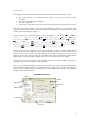
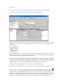
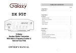
The upper left part of the ArgoUML window, the Explorer Pane, shows a tree model of diagrams and
objects. This view can be adapted to your needs by filtering the objects that are shown, and the
structure in which they are shown. The upper right part of ArgoUML, the Edit Pane, shows the current
diagram (one at a time). The lower right part, the Details Pane, contains various details of the currently
selected object. The lower left part currently contains a list of all ToDo items for this model.
The status bar is at the very bottom of the ArgoUML window and is used to display short advisory
messages. In general such messages are self explanatory.
You can re-size panes by dragging on the divider bars between them. Take note of the expand/contract
control beside the package symbol for “untitledModel” in the Explorer Pane. This has Class Diagram 1
and Use Case 1 by default. By right clicking you can delete a diagram from a model. The detail pane
changes to track the selected item.
ArgoUML Screenshot
Titlebar
Toolbar
Menubar
Editing pane
Explorer pane
Details pane
To do pane
-3-
The model may contain many objects (ModelElements) which form the complete UML description of
the system you are describing. All ModelElements might be present on a diagram, but this is not
required.
All diagram types have their own toolbars at the top which are used to create objects on the diagram.
The functionality of ArgoUML can be activated in the menu, in toolbars, or in pop-up menus when
right-clicking above an object.
the Editing Pane Toolbars
The toolbar at the top of the editing pane provides the main functions. If you put the mouse pointer
over an icon a tool tip will tell you what it is.
The tools fall into four categories.
Layout tools. Provide assistance in laying out model elements on the diagram.
Annotation tools. Used to annotate model elements on the diagram.
Drawing tools. Used to add general graphic objects to diagrams.
Diagram specific tools. Used to add UML model elements specific to a particular diagram
type to the diagram.
Layout tools: The broom
Button 1 motion with this tool provides a “broom” which will sweep all model elements along. This is
a shortcut way of lining things up. The Broom can also be invoked by using SHIFT with button 1
motion when the Select tool is in use. If the designer presses the space bar while using the broom,
objects on the face of the broom are distributed (i.e., spaced evenly). ArgoUML's broom supports three
distribution modes: objects can be spaced evenly across the space that they use, objects can be packed
together with only a small gap between them, or objects can be distributed evenly over the entire length
of the broom's face. Repeatedly pressing the space bar cycles among these three distribution modes and
displays a brief message indicating the operation just performed: Space evenly, Pack tightly, Spread out
and Original. If the designer presses the Enter key while using the broom, the broom turns red (instead
of the normal blue), and objects are not picked up by the broom when moving forward. It works like
lifting up the broom. Pressing Enter again returns to the normal mode. Additional control of model
element layout is provided through the Arrange menu
Annotation tools.
The annotation tool Comment (
) is used to add a comment to a selected UML model element.
Drawing tools.
These are a series of tools for providing graphical additions to diagrams. Although they are not UML
model elements, the UML standard provides for such decoration to improve the readability of
diagrams.
Diagram specific tools - discussed later.
The editing pane is provided with a background grid which can be set in various styles or turned off
altogether through the menu.
Within the editing pane, a button 2 click over a model element will bring up a pop-up menu with a
variable number of main entries, many with a sub-menu.
Creating a Simple Class Diagram
(from User Manual and notes by Mei Zhang)
Diagrams are drawn by using the edit pane toolbar to select the model element desired and clicking in
the diagram at the position required.
-4-
You can further move the model element on the drawing canvass before releasing the mouse button.
You can nudge a fig by selecting an element and using arrow keys.
The default tool is the Select tool (
). In general button 1 click on any tool selects a tool for use.
For most tools, adding a new model element to the diagram is achieved by moving the mouse into the
editing area and clicking again.
Create a class
Use
Class to add a class to the diagram. Name the class Customer by clicking on the red squiggly
line and typing Customer. Right-click on class and select Add. ArgoUML assumes a two button mouse.
This sub-menu appears for model elements that can have operations or attributes added (class,
interface). Enter a name called name of type String (UML 1.4) with public visibility (default) in the
Properties tab.
To delete the class, right-click and select delete or use delete icon in properties pane. You can also
remove something form a diagram without removing it from the model (by selecting and pressing the
delete key).
A key feature of ArgoUML is the critics, which run in parallel with the main ArgoUML tool. When
they find a problem, they typically raise a to-do item, and also highlight the problem on the editing
pane. The graphical techniques used for highlighting are called Clarifiers. Coloured wavy lines (
) underline attributes with a problem within a class. Note icons ( ) displayed at the top
left of a model element indicate a critic of that model element. Moving the mouse over the icon will
pop up the critic headline.
Now right-click on class and select Show. This sub-menu only appears with certain model elements. It
is completely context dependent. You can show/hide various compartments such as Attributes and
Operations.
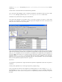
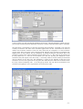
Setting Properties
The Properties tab is the most important part of the Details pane.
At the top left is the icon and name of the type of model element. To the right of this is a toolbar of
icons relevant to this property tab. The first one is always navigation Go up. The last is always
Delete to delete the selected model element from the model. The ones in between depend on the
model element. If there are too many to display a >> icon can be used to show the rest.
New
attribute creates a new attribute within the class, navigating immediately to the properties tab for
that attribute.
New operation creates a new operation.
The remainder of the tab comprises fields, laid out in two or three columns. In most (but not all cases)
the values can be changed. Name is the name of the model. Visibility has entries public,
private, protected. Attributes lists all the attributes defined for this class. Operations
lists all the operations defined on this class. Note that the namespace is UntitledModel
Attributes
An attribute is represented in the diagram on a single line within the attribute compartment of the class.
Its syntax is as follows:
visibility attributeName : type [= initialValue]
-5-
visibility is +, #, - or ~ corresponding to public, protected, private, or package visibility
respectively.
attributeName is the actual name of the attribute being declared.
type is the type (UML datatype, class or interface) declared for the attribute. This can be any UML
Classifier, although in practice only Class, DataType, or Interface make sense.
initialValue is any initial value to be given to the attribute
Note about class diagrams in ArgoUML: There is currently no support for objects or links within
ArgoUML class diagrams. Instead the ArgoUML deployment diagram does have both objects and
links, and can be used to draw object diagrams.
Now we will add an operation. There are multiple ways of doing this. Right-click on class and select
Add and select Operation, double-click on Operations compartment of class (The third part of default
class), or set in properties tab. We will add it to Properties tab. Double-click new Operation in
Operations field. This brings you to a separate property sheet for the operation. Instead you could have
clicked the
New attribute icon in the top left. Enter the name creditRating in the name field.
Make the return type String (from type drop-down menu of “return parameter”. note you can navigate
back up to the Operations properties with the ^ up arrow.
Operations
An operation is represented on a single line within the operation compartment of the class. Its syntax is
as follows:
visibility name (parameter list) : return-type-expression {property-string}
You can edit this line directly in the diagram, by double-clicking on it. The visibility is +, #, - or ~
corresponding to public, protected, private visibility, or package visibility respectively.
There may be zero or more entries in the parameter list separated by commas. Every entry is a pair of
the form:
-6-
name : type
The return-type-expression is the type (UML datatype, class or interface) of the result returned.
Finally the whole entry is shown in italics if the operation is declared abstract.
Next we will create subclasses. Again there are various ways of doing this. For convenience, when the
mouse is over a selected class it displays handles which may be clicked or dragged to form
relationships.
ArgoUML displays some “selection-action buttons” around the selected model element. For example, a
class node has a button at 12-o'clock for adding a superclass, one at 6-o'clock for adding a subclass, and
buttons at 3-o'clock and 9-o'clock for adding associations.
Use the 6-o'clock handle for adding a subclass. a single click creates a new related class at a default
position relative to the original class and creates a generalization or association; a drag from the button
to an existing class creates only the generalization or association; and, a drag to an empty space in the
diagram creates a new class at the mouse position and the generalization or association.
Name this class PersonalCustomer. Add an attribute creditCard# of type Integer.
If you select the subclass and move it the association will stay tied to the subclass and superclass.
Another way to create a subclass is to first create the class and then add the association.
Generalization adds a generalization between two model elements selected using button 1.
Generalization is a relationship between two use cases or two actors. Where A is a generalization of B,
it means A describes more general behavior and B a more specific version of that behavior. Click on
association to view its properties. Note the values for Parent (superclass) and Child (subclass).
Discriminator allows grouping of specializations into a number of sets, on the basis of this value.
-7-
Create an Order class with the attributes dateReceived (Integer), isPrepaid (Boolean), number (Strring),
price (Integer) and the operations dispatch() and close(). Create an association from Order to Customer.
The association is represented as a solid line connecting classes/interfaces. ArgoUML is not restricted
to binary associations. The name of the association appear above the line. Associations are often not
named. The association contains at least two ends, which may be navigated to via the association
property sheet. These are shown in the Connections field. Selection of an association in a diagram with
display boxes for these details. Set the multiplicity by double-clicking the Association end in the
association property sheet. Set the multiplicity for the Order end to 1..*. The value can be chosen from
the drop down box, or a new one can be edited in the text box. Records the multiplicity of this
association end (with respect to the other end), i.e. how many instances of this end may be associated
with an instance of the other end. The multiplicity is shown on the diagram at that end of the
association. You can also right-click the end point (The small black box where the association meets
the class). Choose multiplicity and 1..* from the pop-up menus. One can also set the direction of an
association (navigability). This is represented as an arrow-head in UML.
-8-