1
International Journal of Emerging Technology and Advanced Engineering
Website: www.ijetae.com (ISSN 2250-2459, ISO 9001:2008 Certified Journal, Volume 3, Issue 11, November 2013)
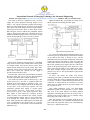
The system is driven by a regulated 5V DC, 1A power
supply. The system design has been kept simple so as to
realize a less expensive miniature portable lab prototype
model. The 4x4 keypad has been used to key in the desired
motor speed. The LCD displays the desired speed and the
actual speed of the motor. There are three LEDs of Red,
Blue and green colour to indicate the comparator outputs
status i.e. Equal, Greater and Lesser. The motor driver is an
additional attachment designed in the Lab with just enough
current driving capability to drive a 6V DC toy motor.
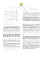
Higher the PWM duty cycle higher the voltage across
the DC motor, thus increasing the motor speed.
Fig:2 Closed Loop Control System
Fig: 3 shows the PWM signal with different duty cycles.
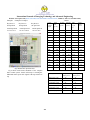
The motor speed is encoded using a slotted wheel mounted
on the shaft of the motor as shown in Fig:7. The IR
transmitter and receiver mounted on both sides of the wheel
registers the absence and presence of the slots when the
slotted wheel mounted on the motor shaft is rotating. The
IR receiver generates pulse signal at the rate of the motor
speed. In the present design the motor wheel has 8 slots,
thus 8 pulses are generated per one rotation of the wheel.
The speed feedback sampler counts the motor encoder
pulses at every one sec. The speed feedback is passed to the
error comparator.
Dc Motor: DC motors are widely used because
controlling a DC motor is somewhat easier than other kinds
of motors. When DC voltage is applied with proper current
to a motor, it rotates in a particular direction but when the
connection of voltage between two terminals is reversed,
motor rotates in another direction. In present design a 6V
DC toy motor is used.
Pulse Width Modulation (pwm): The Pulse-WidthModulation (PWM) in microcontroller is used to control
duty cycle of DC motor. PWM is an entirely different
approach to controlling the speed of a DC motor. Power is
supplied to the motor in square wave of constant voltage
but varying pulse-width or duty cycle.
Since the frequency is held constant while the on-off
time is varied, the duty cycle of PWM is determined by the
pulse width. The expression of duty cycle is determined by,
Duty cycle = (ON/ON+OFF)*100.
Fig:1 System Level Block Diagram
Motor driver module has been designed as a detachable
entity so that it can be used in another motor control system
for example FPGA based motor control system. Three
signals namely PWM, motor speed encoder pulse and a
ground are used to connect between the 8051 KIT and the
motor drive control unit. Separate 6V DC supply is
provided to the motor driver unit.
The 8051 KIT connected to keyboard and LCD without
the motor driver unit can be used for other applications
based lab experiments such as simple calculator etc.
The closed loop control system is shown in Fig- 2. The
desired speed set by the user is compared against the
feedback speed. The feedback is sampled at every 1 sec
interval. However this sampling interval can be changed to
see the effect of the closed loop response. The error
comparator generates three signals i.e. Greater, Equal,
Lesser when the set speed > actual speed, set speed =
actual speed, set speed < actual speed respectively. These
three signals in turn controls the following up/down
counter. Positive error increments the counter, negative
error decrements the counter, and at no error counter value
is not changed. The counter output is passed to the next
block which generates the PWM signal. The PWM duty
cycle is proportional to the counter value. So, a positive
error increments the count, which in turn increments the
PWM duty cycle.
381