1
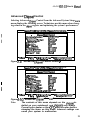
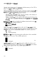
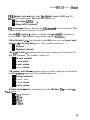
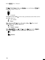
LPA POUUTION
-PHLVLNTER
AL486 ’ VIOkI3
M
r
A
N
U
A I_
y!
I
r
4
UC ontents
Introduction
General Specifications . . . . . . . . . . . . . . . . . . . . . . . . . . . . . . . . . . . . . . . . . . . . . . . . . . . . . . 1
Memory Configurations
System Memory . . . . . . . . . . . . . . . . . . . . . . . . . . . . . . . . . . . . . . . . . . . . . . . . . . . . . . . . . . . . . 4
Cache Memory Configuration . . . . . . . . . . . . . . . . . . . . . . . . . . . . . . . . . . . . . . . . . . . . 4
Jumper Settings and Connectors
Setting the Jumpers ......................................................... 5
ColInectots ................................................................... 9
Board Layout ............................................................... 10
Built-in BIOS SETUP Program
Setup Program .............................................................. II
System Setup ................................................................ 13
Fixed Disk Setup ........................................................... 14
Advanced System SETUP ................................................ 16
Boot Options ................................................................ 25
Security and Anti-Virus ................................................... 25
Green PC Features ......................................................... 27
Load ROM Default Values ............................................... 30
Load Values from CMOS ................................................ 31
Save Values to CMOS ..................................................... 31
Quitting Setup .............................................................. 33
BIOS Errors and Messages ............................................... 33
Appendix A
Setting the System Speed . . . . . . . . . . . . . . . . . . . . . . . . . . . . . . . . . . . . . . . . . . . . . . . . . 40
1 Introduction
AL486 VIO-U3 is a 486 VL-Bus mainboard based on the Acer M 1429G
and M 143 I system chipset. Other on-board specifications include memory
capacity of up 64MB, cache memory sizes of 64/128/256 KB, and the
Green function support that complies to the standards of Energy Star.
1 1
l
General Specifications
Processor:
Traditional CPU (486, 4860X41, Intel S-Series,
Pentium overdrive P24T circuit ready, M6, M7
External Cache :
Supports 64/l 28/256 KB
Memory Size:
Four 720pin SIMM sockets supporting single
density SlMMs only
Memory size of 1 MB up to 64MB
System BIOS:
Phoenix BIOS
Slots :
One VL-Bus slot and one 120 pin (Standard
ISA 98 pin plus, six special purpose Gnd, VCC
pins) Bus slot
Connectors:
Standard Power connector
3.3/3.45\1 Power Connector (option)
PS/2 Keyboard Connector
PS/2 Mouse Connector
COMl /COM2
Printer Port
VGA Connector
VGA Feature Connector
VL Bus IDE Connector
FDC Connector
Hardware Reset Connector
Ext Speaker Connector
Keylock Connector, Power LED
HDD LED
Form Factor:
LPX
PCB :
4 layers
AL486 VIO-U3 User’s Manual
Features
n
n
Internal Cache:
- Supports Ll write-through feature of 486 systems
- Supports Ll write-through/write-back feature of
P24TlP24Dh46lM7 systems
- Supports enable/disable on Ll write-back for entire local memory
space of P24T/P24D/M6/M7 systems
- Supports optional enable write-back in region > = 16MB of
P24T/P24D/M6/M7 (for ISA compatibility issue)
- Cacheable to BIOS code Read with default of write-through by
P24T/P24D/M6/M7, non-cacheable to BIOS data read/write to protect or write-through to BIOS data read/write
External Cache :
- L2 write-back or write-through, but no write-buffered for one-bank
or two-bank, TAG bit and Modify bit in one SRAM
n
Fast Local Bus:
- Allows ISA master/DMA access to local device
- Allows local master access to ISA device
n
DRAM:
- Supports 256K/Sl2K/lM/4M/l6M with 8011s or faster DRAM speci-
fications
- Page Mode only
- Hidden refresh/Slow ref~sh/Normal refresh
2
AL486 VI043 User’s Manual
q
SMM and PMU:
- Supports CPU SMM Mode, SMI feature
- STPCLK control with clock scaling
- I/O trap for I/O restart feature
- Supports the APM control
- Supports the EXTSMI corltrol for indicating the power saving state
- 4 system state for power saving (1) ON (2) DOZE (3) STANDBY
(4) SUSPEND
- Programmable Flash LED (Turbo LED), indicate Power saving
StAtUS
-
Peripheral devices activity monitoring of each state for power saving: KBD, VGA, HDD, LPT, COM, FDD, IRQS, DRQS, VESA
master and 2 programmable regions
- 7 timers from 1 second to 320 minutes to individually monitor the
state, VGA, HDD, LPT, programming region I, programming tegion 2, and standard input devices activity
- External switch, RTC alarm, and modem ring-in wake up control
n
Built-in ISP controller and RTC
n
Software AT clock programmable
n
Supports Flash ROM, EPROM
WS upports I/O Recovery
n
Fast RC, Gate A20 emulation
3
At486 VIO-U3 User’s Manual
2 Memory Configjurations
In this section, the AL486 VIO-U3 DRAM and cache configurations are discussed. Users are recommended to read through this section before installing or removing memory.
2.1 System Memory
The AL486 VIO-U3 DRAM provides tremendous flexibility to support a
number of different on-board DRAM configurations. The on-board DRAM
is installed with SIMM (Single-In-Line Memory Module). There are four
memory banks capable of supporting 1MB up to 64MB. 72.pin SIMM modules must be installed in every banks without any order.
The following table lists all the possible DRAM module combinations and
the total memory amount for each option.
2.2 Cache Memory Configuration
AL486 VI043 User’s Martrd
3 Jumper Settings and Connectors
3.1 Setting the Jumpers
The table below summarizes the functions and appropriate jumper settings
on the AL486 VIO-U3.
P----i
. Function
486SX
Jumper Set tinge
- JP54 open
JP60 open
JP61 short 2-3
JP62 open
JP63 open
JP64 short 2-3
JP66 short 1-2
JP70 open
JP73 open
JP54 open
JP60 short 2-3
JP61 shott 2-3
JP62 open
JP63 open
JP64 short l-2, 3-4
3466 short l-2
JP70 open
JP73 open
JP54 open
JP60 shott l-2
JP61 short 2-3
JP62 open
JP63 open
JP64 short l-2, 3-4
JP66 short l-2
JP70 open
open
.--JP73
-_
JP54 short
JP60 short 2-3
JP61 short l-2
JP62 short
JP63 short l-2
JP64 short l-2, 3-4
JP66 short l-2
JP70 open
JP73 short l-2
--
4860X
CPU Type
487SX
?4S/P24S
Settings (Continued . .
5
AL486 V/O-U3 User’s Manual
Function
M7
CPU Type
P23S
P24C(OX4)
M6 System
CPU Type Set for the
M7 System
Syrtem ContraMet
486 81 Upgradeable 486
System
Amper Settings
JP54 short
JP60 open
JP61 short l-2
JP62 open
JP63 short 3-4
JP64 short 2-3
JP66 short 1-2
JP70 open
JP73
_-- short 3-4
3954 short
JP60 short 2-3
3961 short l-2
JP62 open
JP63 short 3-4
JP64 shaft l-2, 3-4
JP66 short l-2
JP70 open: 1 XCPUCLK
short: 2XCPUCLK
(for OEM CPU
only)
JP73 short 3-4
JP54 short
JP60 open
JP61 short l-2
JP62 short
JP63 short l-2
JP64 short 2-3
JP66 short l-2
JP70 open
JP73 short l-2
JP54 short
JP60 short 2-3
JP61 short l-2
JP62 short
JP63 short l-2
JP64 short l-2, 3-4
JP66 short l-2
JP70 open
JP73 short l - 2
JP40 short
JP42 open
JP44 short
SP40 open
JP42 open
JP44 short
JP40 open
JP42 open
JP44 open
AL486 VIO-U3 User’s Manual
-A
Function
25 MHz
CPU Speed Select
33MHz
40 MHz
+5V
CPU Voltage
LT1085 + 3.45V
+ 3.31+ 3.45v Power
SUPPlY
64K
Cache Size
128K
256K
--- FIash ROM
---.- -
+12v
..--_..-- +5v
Display Adapter
._-__ _.. -~
On-board VGA
On-board I/O
__ ~ - .___-__I_
Local IDE
Normal
CGA
Disabled
Enabled
Disabled
Enabled
-._
Disabled
Enabled
_ ____-_--_____
Jumper Settings
- - - - - - - JP37 short l-2, 5-6
open 3-4
JP43 short l-2
JP53 short l-2
JP55
short l-2
___--______.-JP37 open l-2
short 3-4, 5-6
JP43 short l-2
JP53 short l-2
JP55
short l-2
__-----JP37 short l-2, 3-4
open 5-6
JP43 short 2-3
JP53 short 2-3
-_
-JP55- short 2-3
JP80 short
JP79 open
JP84 open
JP67
short l-2
__-JP80 open
JP79 short
JP84 open
JP67 short 2-3
Jp’80 open
JP79 open
JP84 short
JP67 short 2-3
JP75 short l-2
JP74 open
3P41 open
JP75 short 2-3
JP74 short
JP41 short l-2
._--~~JP75 short l-2
JP74 short
J_P41 short l-2, 3-4
J_P4 short l-2
JP4
short 2-3 _-_______--.
________---.JP5
short l-2
________.___
______I___.
JP5
short 2-3
._--____I_-_----~.JP6--short
2-3 -P-P
-_
. e-eJP6
short l-2
_-_______--wJP12 short 2-3
---_--p
JP12
short l-2
____--JP50 short 2-3
.--pJP50 short l-2
7
AL,486 VIO-U3 User’s Manud
Function
EPP & ECP
Enabled
Disabled
IRQ5
k7
DRQl /DACKl
ECP DMA Channel
Jumper Settings
JP24 short 2-3
JP15 short 2-3
JPl0 short l - 2
JP15 short l-2
Def auk Setting
Note1 :
JP79, JP80 will be shorted if the 3.3V power connector
is not installed.
JP65: M6/M 7 short 2-3, other open
JP82: M6/M 7 short 2-3, AM0 short l-2, other open
JP8 1: For P24C open 3X, short 2-3 2X
Note2:
A MD Microprocessors - The AM0 OX2 (0 sepping, NonSMt CPU) series microprocessor cannot support DOZE,
STANDBY, and SUSPEND modes. The AM0 DXL2 (E
stepping, SMI CPU) microprocessor can support the
DOZE, STANDBY, and SUSPEND modes but the CPU
speed is only decreased to 8MHz state instead of a stop
clock state when running in SUSPEND mode.
The AMD DXLZ CRf uses the PLC c&cd@ wllticlt prevents N f’m
rlfppotthg wop dock -.
I1
AL486 VI043 User’s Manual
3.2 Connectors
There are several connectors located on the AL486 VIO-U3. They are used
to connect some peripheral devices to enhance the operating perfomlance of
the system. Refer to Figure 3.1 for the positions of all the connectors on the
mainboard. The following table lists the connectors on the AL486 VIO-U3.
Connector
-_---
- -.
Jl
Printer Port
J2
COM2
J3
-
-
__I__--_ - . - --p
I
COMl
I
VGA Connector
I
EXT. Battery
J7
I
Feature Connector
J9
I
VL Bus IDE Connector
310
I
FDC Connector
34
-
Function
I
311
l-3 Power LED, 4-5 Keylock
JP2
PSt2 Mouse
JP3
I
I
PSI2 Keyboard
Moden Ring-in Connector
JP9
I
External Switch for Suspend/Resume
JPlO
I
I
Standard Power Connector
JP30
+ 3.3/3.45V
Power Connector
9
AL486 VIO-U3 User’s Manual
3.3 Board Layout
PS12
Mours
VGA
I
Pt inter
L
PS/2
Keyboard
COM2
Standard
Power
Feature 2
Connector
SuPPlY
Conm?ctor
+ 3.45vt + 3.3v
Pa wer
TAG
RAM
SuPPlY
Connector
1
Jl#r
r
Figure 3- 1. AL486 VIO-lJ3 h&inboard Layout
10
AL486 VIO-U3 User’s Manlral
4 Built-in BIOS Setup Program
4.1 Setup Program
Use the BIOS for AL486 VIO-U3 to record changes in your hardware and
to control its special features. The Setup program uses a nunlber of menus
in which you can specify changes to your hardware and turn the special features to on or off.
To cuter the BIOS Setup program, turn on or reboot the system. Press the
< DEL > key when the system displays the following message:
Press < DEL> to enter Setup. The following screen will then be displayed.
thwntx Beta) - Cmr@ht ¶9Y2-94 ?hwnlx Techmolo#Ico ttl.
SBW VBlrn
to tnm
4
tl cbw
t1 nelp
9
.
tee? select
tsc Exit
Figure 4- 1. Setup Main Menu
110 SBwacxlt
d
It is highly recommended that you list down all the values of the Setup program before making any changes. Doing so will save a lot of time restoring
the system back in the event of a configuration memory loss.
Note:
n
On-screen instructions at the bottom of each screen explain how to use the program.
System Setup - allows checking or modification of general configuration information.
11
AL486 WO-U3 User’s Manual
Fixed Disk Setup - allows for automatic detection of the hard disk
drive type including the number of cylinders and heads write pre-compensatlon time, read/write head landing zone, and number of sectors
per track.
Advanced System Setup - sets the various system options for the
user, including the internal/external cache memory Wtions, ISA features, video and system shadowing etc..
Boot Options - determines the sequence with which the system will
proceed when booting the operating system.
Security and Anti-Virus - rovides special access for the user to enter the operating system and Betup program, and restricts unauthorized
access to the floppy disk drives.
Green PC Features - allows the timer settings for the DOZE,
STANDBY and RESUME modes. It also lists the SMI events by which
the system wakes u from STANDBY or SUSPEND modes. If the device 1s not active, Iowet Management Function will slow down the
CPU speed and both IDE and monitor will be put into’doze, standby,
or suspend mode.
Load ROM Default Values - allows for automatic confi uration of
all the above options using the values in the ROM BIOS ta%le.
.
Load Values from CMOS - allows for automatic confi ration of all
the above options using the previous values saved in the PMOS SRAM.
Save Values to CMOS - saves the changes you have made in the
Setup program, then quits and reboots the system.
To choose an item from the Setup main menu, move the cursor to appropriate line using the Up < ? > and Down < 4 > arrow keys and press < Enter>.
12
AL486 VIO-U3 User’s Manual
4.2 System Setup
symten setup
symtca ttae:
System Date:
fDj:SO:S91
1.4/01/1994 1
Ul4ea syeten:
ma 0 U6Al
symttn lhory:
ItYmded fkaory:
Dimlstte Drlw I):
B:
Dlmkette Drlw
tl mow
ESC txit
?l tld)
63D WB
at744 KB
Cl.2 1111, S8"l
tnet lnmtrltadl
tgup rreriamr ua Iae
?gDn
Next Value
A
Cs frsufoua Configrrotion
r6 Default Conflgrratian
Figure 4-2. System Setup
System Time - includes hour, minutes, seconds but only the values of hour
and minute can be set.
System Date - allows manual setting of the electronic calendar on the mainboard.
Video System - specifies the display adapter installed.
Hard Disk C: and Hard Disk D: - specify the physical and electronic prop
erties of the standard hard disk drives installed. Relevant specifications include the number of cylinders, heads, write pre-compensation time,
read/write head landing zone, and number of sectors per track.
System Memory and Extended Memory - displays important information
about your system which includes the conventional and extended memory
sizes. They are updated automatically by the Setup program according to
the status detected by the BIOS self-test. This section of the System Setup
screen is for viewing purpose only and manual modifications are not allowed.
Diskette Drives A: and B: - specify the capacity and f;ormat of the floppy
drives installed in your system.
13
AL486 VIO-U3 User’s Mama1
4.3 Fixed Disk Setup
The Fixed Disk Setup provides auto configuration of the hard drive installed in the system. After pressing the < Enter > key on this item on the
main menu,. the screen will display the following screen.
?bwrlx Satmp -
Cupjpl@t
lY#-Yl ?ha~rlx TechwIoplw Ltd.
?lxtl #Irk
sctrp
Figure 4-3. Fixed Disk Setup Screen 1
Once the program detects the type of hard disk 0 and/or I installed, it will
display the relative information such as the type, cylinders, heads, write precompensation, landing zone, and number of sectors per track.
rhwntx
!hBtmp - copjpr*t
tl
I1
now
)Irlp
Intar
tsc
I,#-n
moertx
se1mct
txlt
Figure 4-4. Fixed Disk Setup Screen 2
14
TeckRoIqllw
Il. Srwltbtl t
tu.
AL486 VIO-Cl3 User’s Manual
If the program faiis to detect the hard disk(s) or the < Enter > key was not
pressed in the Autotype Fixed Disk option, manual setting of the values is
recommended.
Autotype Fixed Disk - detects the type of fixed disk 0 anNor I installed. If
successful, it fills the remaining fields on this menu.
Type - I to 45 fills in remaining fields with values for predefirled disk
drives. “User” allows the user to fill in the remaining fields.
Cylinders - specifies the number of cylinders of the hard disk drive. The
range of this option is from 1 to 1024.
?leatls - specifies the number of read/write heads of the hard disk drive.
The range of this option is from 1 to 16.
Sectors/Track - provides the number of sectors per track defined for the
hard disk drive. The range is from 1 to 64.
Landing Zone - refers to the cylinder number where the disk drive heads
(read/write) are positioned to when the disk drive is parked. The range of
this option is from 1 to 1024.
Write Precomp - refers the cylinder number, above which, disk drive operations require reduced write current. Also specifies the number of cylinder at which to change the write timing. The available options are from 1 to
1024 and None.
15
AL486 VIO-U3 User’s Mawal
4.4 Advanced System Setup
The Advanced System Setup allows the user to program three main groups
of parameters under the Advanced System Setup namely the System Timing, the Memory Shadow, and the Advanced chipset Control. This BIOS
Setup parameter is designed for programmers who wish to fine tune the onboard chipset.
tlmortn sotup - copyrt$bt m!tz-94
ttbo8ntr Technotoglom
uwmud slptw
Ltd.
s8tup
lkrnt ngt
tf l o* tuorrectly,
l gota to aa1frmt1ow.
ttow
on tLt0 Rome
cmtd umu year
ti ttow
rlbtor
tsc
ll WJtp
3818d
e!rtt
tie
3rrslErtt
Figure 4-5. Advanced System Setup Screen
Integrated Peripherals
Selecting System Timing from the Advanced System Setup main menu display the following screen. The actual features displayed depend on the capabilities of your system’s hardware.
.
I
ttumatr set8p - cqgtt#bt l992-94 ?tmertr tcrJI#te#tm tu.
t1
mw
mc
11
&It
lb:)
tllu, trovtou uBtro
tgmn
tbxt &IS8
Figure 4-6. Integrated Petipherals
n trovtBoo comft~ttw
tr) kfwtt bnft~tton
AL486 VIO-U3 User’s iUam~1
COM port 1 - assigns the address of the primary serial port on-board. The
available options are listed below.When you select “Auto”, the system will
detect addon card comport address to avoid comport address conflict.
l
l
l
l
l
Auto
3F8-IRQ4
338~IRQ4
2E8-IRQ4
220~lRQ4
Disable
2F8-IRQ3
0 2E8-IRQ3
l
2ED-IRQ3
l
228~lRQ3
l
l
COM port 2 - assigns the address of the secondary serial port on-board.
The available options are list below.
l
l
l
l
l
Auto
3F8-IRQ4
3380lRQ4
2E8-IRQ4
22D-lRQ4
l
l
l
l
l
Disable
2F8-IRQ3
2E8-IRQ3
2ED-IRQ3
2280IRQ3
LPT Port - assigns the address of the parallel port on-board. This option
also prevents the system from encountering any conflict when an add-on
card with parallel port is installed in the titure. The available options are
list below. When you select “Auto”, the system will detect add-on card parallel port address then set on-board into difkrent address to avoid parallel
port address conflict.
l Auto
l Disable
. 3B7-IRQ7
.
.
378-lRQ7
278-lRQ7
Diskette controller - sets the diskette controller mode of the SMC 665 l/O
chip to either on or off. The available options are:
l
l
Disable
Enable
AL486 VIO-V3 U,cer ‘s Manual
Parallel Port Extended Modes - In “ECP & EPP” mode, EPP can select
through the ECR register of ECP mode 100. In SPP can be selected through
the ECR register as mode 000. The available options are:
l SPP Mode
l
l
l
ECP & EPP
ECP Mode
EPP &SPP
System Timing
Selecting System Timing from the Advanced System Setup main menu displays the following screen. The actual fkatures displayed depend on the capabilities of your system’s hardware.
Figure 4- 7. System Timing Screen
Auto Configuration - Disabling this option allows the values for the other
parameters to be changed. Ennbting it will restrict you From making any
changes.
SRAM read - determines the number of cycle times to be inserted
when CPU reads data to cache. The setting depends on the speed of the
CPU and SRAM. If the CPU is of high speed, the time required by
SRAM to process data will need an extension, with the exception of
some SRAMs that are fast enough to catch up with the speed of the
AL486 VIO-U3 Userk Mama1
CPU. Fewer wait states are recommended to improve the system performance. The available options are:
l
o w s
l
IWS
SRAM write - setting of this parameter makes no difference from that
of the SRAM Read. This option sets the number of wait states to be
added on writes to cache memory. Fewer wait states are recommended
to improve the system performance. Check the CPU speed and SRAM
before changing the default value. The available options are listed below .
l
ows
.lWS
*
DRAM read - determines the number of wait states to be inserted
when the CPU reads data into the local DRAM. Fewer wait states are
recommended to improve the system performance. The following are
the available options.
l Slow
l Normal
l Fast
DRAM write - detemlines the number of wait states to be inserted
when the CPU writes data into the local DRAM. Fewer wait states are
recommended to improve the system perfomlance. The following are
the available options.
l Slow
Normal
l
Fast
Cycle Check Point - allows you to select the rate for check point to determine whether it is a “hit” or a “miss” of the SRAM TAG. The available options are:
l Slow
l
l
Normal
Fast
AT Bus Clock Select - specifies the speed of the AT Bus clock of the
systent. The only available option and default value is 7.19MHz
l
19
AL486 VIO-U3 User’s
Man14al
Memory Shadow
Selecting Memory Shadow from the Advanced System Setup main menu displays the following screen. The actual features displayed depend on the capabilities of your system’s hardware.
.
?hoentw Setmp - Cspyrl#ut
I
8) Row
@SC
Sprtor
Uldeo
hrdou:
l
l hadw:
Shadou
?kaoty De@me
am - cm:
DWD - mw:
Doea - NW:
mctt
lYYt-!I4 ?Rwrlr Tethwlgtem ttd.
Lnbblrd
ammt
tDlmablcd1
tblrrbled~
tblubhhd~
?#I? ?reuloum Uelre
rglh
lhIme
next
Figure 4-8. Memory Shadow Screen
ll kl)
85 ?‘rusloes CemC lprrtlon
rs
Dorbrlt Codlqubt1olb
System shadow - allows shadowing of the system BIOS and improves the
system performance. This option is always set as En04!5led.
Video shadow - sets the mode of the system’s video BIOS shadowing
mode. The available options are:
q Enabled (default)
n
Disabled
Shadow Memory Regions - shadows the option ROM located in the specified blocks of memory, and can improve the system performance.
Note:
20
Some option ROMs do not work properly when shadowed.
AL486 VIO-U3 User’s Mariiicll
Advanced Chipset Control
Selecting Advanced Chipset Control from the Advanced System Setup main
menu displays the following screen. Technicians use this menu when changing values in the chipset register and optimizing the system’s performance.
?hmlblx tkttmp - CopyrQJht tmz-w moerlx technologlse Ltd.
.
.
tntcrnrt cede tcetrrc:
Extarnr1 cethe:
txtrrnrl cache I eatare:
crcherbte:
tllddm rotrreh:
?e,l ty check:
llltru tlalnl:
MS to ens ddry:
vl!sn ruter cyck
IAI rewuary:
OwehIp IAl recorery:
I!##
m/m:
13n IAD
l
3kblu
wrlta imsrt
u&it tate:
11 liars
Bxlt
tsc
I1 lklp
7
M~md CIl poet Control
tlfJmmr0mmglr
ICMbIell
I
Cblerble~l
ttnrbldl
tblubtell
t6tJ
t1tg
WeIry CIDSJI
tblubtedl
tD1ub1edl
tbtmablall
I
tur tc brck I
tRomrl
?@p Ixwlome Value
rq)n auxt UaIme
t
.
rS ?rerloue Confl~rrtlon
t6 Wefmalt Cedtgurrtla~
Figure 4-9. Advanced Chipset Control Screen 1
?heealx
setup - Cepyrlght
tY92-!M ?hwnix techmalogiso
Ltd.
l
Mr~nccd Chlpret ContraI
tlrln@:
lIImJ
RAS to CM de1.y:
WEB8 nmmtcr cycle:
tAB meowerg:
Da-chip I/O retorery:
tm
I!M I/w
l
ts1) aemmy uast rtetet
Islreoh pert d
U/3 Ir, 32-bit t3cI:
Local Dculce Dyn. Rode:
Delay Iaterlml msJ:
Dohy IDh4DWJ check In CLR2:
mat8 Inwrt v/m:
UBlt
tate:
:
11 lhal
G3c Cxl t
ll Help
tml
t4tt
tDe1ry ADSI
tllrrbledl
tblsrblcdl
CDImrbIedl
I8
tmwmelt
Cl5 ral
tot1
tsyn. 1
tblmmbladl
t31
nlora~
r#p rrsrlom8 uetre
?gDn Next UaI8e
IS ?reuioa8 Coatlgrrrt~on
I6 l&tauIt Cenf Igwrtlar,
Figure 4- 10. Advanced Chipset Con trot Screen 2
Note:
The contents of this menu depends on the chipset installed on your mainboard, and chipsets vary widely.
Consult your dealer or the < Ff > help screens before
changing the items on this menu. Incorrect settings can
cause your system to malfunction.
21
AL486 VIO-U3 User’s Mama1
Internal cache feature - sets the internal code/data memory of the CPU to
either
Write back or Write through (default).
External cache - sets the function of the second level cache on-board. If Encrhk! (default), the settings of the following options can be set. Disabling
this option witl deem the following options useless.
External cache feature - sets the external secondary cache memory to
either Write back (default) or Write through.
Shadow cacheable - must be enabled when shadowing for both system
and video BIOS is present. Otherwise, set this option to off or Disabfed
(defaul Q.
Hidden Refresh - enables or disables the hidden refresh mode for the on-
board mentory. The available options are:
n Enabled (def au(t)
m Disabled
Parity Check - During a local memory read cycle, the M1429G not only
tttonitors bus steering, but also checks the parity bit for each data byte from
DRAM to ensure that the correct data is read. The available options are:
n Enabled
q Disabled (default)
HITMJ timing - indicates the timing pulse width when a hit to a modified
data cache is set to occur. The available options are:
q
2t
H 3t
W 4t
m 6t (default)
.
RAS to CM delay - specifies the timing pulse width where the row address strobe (RAS) will be on the falling edge and followed by the column
. address strobe signal (CAS). The available options are:
q 2t
m 4t (default)
m 6t
22
AL486 VIO-U3 User’s Mwwal
VESA master cycle - sets the delay ft,r chipset to check ADSJ after VL
Master cycle check point. The available options are:
.
m Non-delay ADS3
m Delay ADSJ (default)
I/O recovery - enables or disables the 110 conlnlat#l recovery function. The
default setting for this option is Disabled.
On-chip I/O recovery - enables or disables the onchip I/O command recovery feature. The default setting for this option is Dis&ed.
ISA write insert w/s - sets the mode of the ISA write cycle end insert wait
state for stat data hold timing issue. The available options are:
1111 Enabled
m Disabled (default)
ISA I/O wait state - determines the wait states setting to be inserted to the
ISA I/O command. The available options are:
111 Normal (default)
H 1 wait state
111 2 wait states
m 3 wait states
ISA memory wait state - determines the wait states setting to be inserted to
the ISA memory command. The available options are:
m Normal (default)
M 1 wait state
m 2 wait states
W 3 wait states
Refresh period - sets the refresh period of the ISA Bus. The available op’ tions a r e :
111 15~s default)
111 3ops
m 60~s
U 12ops
23
AL486 VIO-U3 User’s Manual
W/S in 3%bit ISA - sets the second 16-bit access wait timing in 32-hit ISA
cycle. The available options are:
q 2t
= 4t
4 6t
n 8t (default)
Local Device Syn. Mode - sets the ready synchronous mode of the local device. The options are:
q Syn. (default)
n Bypass.
Delay Internal ADSJ - indicates the mode setting of tile delay internal
ADSJ timing. The available options are:
n Enabled
q Disabled (default)
Delay ISA/LDEVJ check in CLK2 - specifies dre delay for the chipset to
check LDEVJ after the ISA cycle check point. The options are:
Wl
n 2
m 3 (default)
24
AL484 VI043 User’s Mama1
4.5 Boot Options
rhoen~rt
I
11 wlwe
setup -
ISC
I1
Copyrtglt
trttt
lYYZ-Yl
tlmenlx tcchwlogtcm
rs
PgUp hslum Uotu
rgm next Urlu
kl)
?nrlou
I6 Defrr1t
Ltd.
Canfl#mr~tlell
Conflgvratlon
Figure 4- 11. Boot Options Screen
Disk drive boot sequence - sets the sequence from wkre be BIOS will attempt to load the operating system The options are:
111 A: then C: (default)
q C: then A:
4.6
Security and Anti-Virus
rhoerix setup - CopyrIght lYYt-!H
?uawx4 an
DIBketta
tt mew
I1 Mel)
l
fhoenlx
Techwlog~u
Ltd.
beat:
ceu:
triter Set/Ck~
Esc Exit
luurl
?u8d
.
Cwflgurrtim
Is ?mvia*
t(i Ikf rrlt Conf lwrrtlon
Figure 4- 12. Security and Anti- Virus Screen
25
AL486 VIO-V3 User’s Manrml
Supervisor Password is - shows whether the supervisor password is enabled or disabled (de faul t) .
User Password is - shows whether the user password is enabled or disahled (default).
Set Supervisor Password - requires a password when entering Setup. the
passwords are m)t case sensitive. Pressing the < Enter > key will display a
message requiring for the supervisor password which can be up to seven alphanumeric characters. This option also gives full access to the Setup
menus.
Set User Password - Pressing the < Enter > key will display a message requiring for the user password which can be up to seven alphanumeric characters. This option also gives restricted access to the Setup menus and
requires the setting of the Supervisor Password first.
Password on boot - determines whether the password is required on boot.
The option needs the setting of the Supervisor Password. If Supervisor Password is set and this option is dimb&d (default), BIOS assumes that the user
is booting.
Diskette access - restricts the use of floppy drives only to the supervisor
when set as Supervisor (default). Also, choosing Supervisor for this option
will require the setting of the Supervisor Password. Setting it as User allows access to the floppy drives at any time.
26
AL486 VI043 User’s Man~11
4.7 Green PC Features
Ihoenlx *tap - Copydqht 19!!92-Yr
noenlx Technologlea Ltd..
Green ?C featarea
v!lmmm
loucr Sari rg Role:
TlWr:
strnlby Tlwr:
@@tern Doze
syhm
syatcr Srmpbl
flsct
!
Uakmp saptn (Imrln(l l rapsnd:
udmup time at uwar~:
UakcB) time a t trlmtc):
l&h rith twar Born fartare:
ttr*r;c,
tie l ecl
l
t#lrub1co
tRm 12 :I
t 0 rlal)
110
tttone~
~rrncad louer Ranmfpment Setup
*ten mtsre power &muubkewp modea
11
Figure 4 13.
?#p
Exit
I1 tklp
mow
tsc
?gDn
ccf
uetr~
m%t VaIur
bq:
!3 Pnvfoar Conflgurrtlon
Cant lgrrbtlon
?tarlam
16 Befault
Green PC Features Screen 1
?hoonl%
setup -
CoFytlqRt lYYZ-Y4 ?boenlx Yechwlogln Ltd.
Brew ?C teatmrem
:
Cam):
:
(art. p r i n t e r ) :
tCfJlt2)
tbiddte):
ttrlnter):
tAO2 Redlr):
ttkor Define):
tumer krlne):
Wlxd BlatI):
tther Dell nsl :
ltlwl card):
UBN cud):
rllrrerr :
t
to
tmm
tthl
tort I
tltnl
tort t
t0rr I
tort 1
ton1
tOnI
totr 1
torrll
tOnI
tthl
Figure 4- 14. Green PC Features screen 2
.
27
AL486 VIO-U3 User’s Manual
rhomix
ta
llorrs
t3C
setop
kit
t1 Mull,
- Cepplght 1)92-94 Wmenlr TechnoIagiso
f* trert oao UaIro
r@h nmrt hles
fs
Ltd.
??8rloae Conflgaratlor
n Bafm@lt cmr1Ipratton
Figure 4- 16. Green PC Features Screen 3
Power Saving Mode - enables (default) or disables the power saving mode
feature of the chipset. Once enabled, the values of the followitig options can
be set.
System Doze Timer - sets the time interval after system inactivity
when the system enters DOZE mode. The available options are:
l 10 set (default)
l
20/30/90 set
l l/2 mins
l
Disabled
System Standby Timer - sets the time interval after system inactivity
when the system events enters STANDBY mode. The options are:
l
l
l
l
lo/30 set
5 mins (default)
l/2/3/8/1 O/l 5/30 mins
Disabled
System Suspend Timer - sets the time interval after system inactivity
when the system enters SUSPEND mode. The available options are:
l
l
l
l
l
lo/30 set
10 mins (default)
l/5/20/30/40/50 mins
l/2 hrs
Disabled
AL486 VIO-U3 User’s Mama1
Wakeup system during suspend - sets the time when Enabled, in the options
Wakeup time at (hour) and Wakeup time at (minute), after which the
system will return from SUSPEND mode back to RESUME mode. The default setting for this option is Disabled.
VGA with Power Down features - sets the method by which the VGA
chip enters SLEEP mode. The options are:
l
l
None (default)
Standard
Cirrus Logic
. S3 805 (VESA DPMS)
l
The menu also lists the System Management interrupt (SMI) events by
which the system wakes up from STANDBY or SUSPEND mocles. Switch
the following parameters to on or off:
m lRQ3 (COM2)
m IRQ4 (COMl)
m IRQ5 (Alt. printer)
q IRQ6 (Diskette)
m IRQ7 (Printer)
q IRQ9 (IRQ2 Redir)
q
q
q
q
q
IRQlO (User Define)
IRQll (User Define 1
IRQ14 (Fixed Disk)
IRQ15 (User Define 1
DMAl (LAN card)
m DMA3 (LAN card)
q LPT IO address
q Serial IO address
m VESA master event
29
AL486 VIO-U3 User’s Manual
4.8 Load ROM Default Values
If, during bootup, the BIOS program detects a problem in the integrity of
the CMOS, it will display a message asking you to either press the
< DEL > key to run Setup or the < FL > key to resume booting. This probably means that the CMOS values have been corrupted or modified incorrectly, perhaps by an application program that changes data stored in
CMOS.
Press the < Fl > key to resume the boot or < DEL > to run Setup with the
ROM default values already loaded in the menus. You can make other
changes before saving the values to CMOS.
?hoenl
x
Setup - copyr1Qht iv9t-94
Lord
?hmml%
TechnotagtM Ltd.
Wtrluea froa CMOS
srue uatuee to ems
Figure 4- 17. Load ROM Default Values Screen
30
4.9 Load Values from CMOS
If, during a Setup session, you change your mind about your selections atId
have mt yet saved the values to CMOS, you can restore the values you previously saved to CMOS.
Select Load Values from CMOS on the Main Menu and the program will
display the following screen.
?hocnlx
Sctrp
- Copyright 1992-94 Phoenix technologlcs
a
Haln Mem
Ltd.
,
. s~eten setup
Lord Valuer froa Curls
L
Saw thllI88 to al03
F i g u r e 4-18. Load Values from CMOS Screen
4.10 Save Values to CMOS
After making your selections on the Setup nrerrus, always select Save Values to CMOS in order to make them operative. Unlike standard RAM nrenrory, CMOS RAM is sustained by an on-board battery and stays on after
you turn your system off.
After you save your selections, the program will display the following
screen.
31
AL486 WO-U3 User’s hfanual
moenix sstrp - Cqyright
lYYZ-Y4 hoenix Technthglem
Ltd.
P
mm
Figure 4- 19. Save Values to CMOS Screen
If you attempt to exit without saving, the program will ask you if you
would like to save the changes made before exiting.
During bootup, BiOS for the chipset attempts to load the values you saved
in the CMOS RAM. If the values saved in the CMOS cause the system boot
to fail, reboot and press the < DEL> key to enter Setup. Jn Setup, you
may load the ROM default values (as described in the section 4.8) or try to
change the values tJlat caused the boot to fail.
32
AL486 VIO-U3 User’s Mama1
4.11 Quitting Setup
After ruakiilg all modifications in tile Setup program, go to the option “Save
Values to CMOS” then press the < Enter > key or simply press Ure
< FlO> key. The screen will then display a message asking you whether
you would like to save and exit or not.
Use the arrow keys or press < Y > for Yes then the < Enter > key to save
your settings before exiting. Press < N > for No then the < Enter > key to
exit without saving.
If you made cllarlges to the CMOS values and then press the < ESC > key,
tile program will prompt you whether you would like to Quit tihxrt saving
or mf.
Press < Y > for Yes then the < Enter > key to quit without saving, or
press < N > then the < Enter > key to save your settings first before exiting Setup.
4.12 BIOS Errors and Messages
After entering the Setup choices, the system will reboot. The Setup summary aiirt system information will appear on screen along with messages.
These may include ERROR messages concerning the system or Setup.
Phoenix BIOS perfomls various diagnostic tests at the time the system is
turned on. Whenever an error is encountered during these tests, error messages will be displayed on the monitor.
T?le following is a list of all the BIOS error and messages and their corresponding meanings.
nnnn Cache SRAM Passed
Diskette drive A error
Diskette drive B error
Entering SETUP . . .
Extended RAM Failed at offset: nnnn*
Extended RAM Passed
e
33
AL486 VIO-U3 User’s Maw11
Failing Bits: nnnn *
Fixed Disk 0 Failure
Fixed Disk 1 Failure
Fixed Disk Controller Failure +
Incorrect Drive A type - run SETUP
Incorrect Drive B type - run SETUP
Invalid NVRAM media type*
Keyboard controller error *
Keyboard error
Keyboard locked - Unlock key switch
Monitor type does not match CMOS - Run SETUP
Operating system not found
Parity Check 1 +
Parity Check 2*
Press < Fl > to resume, < F2 > to Setup
Press < F2 > to enter SETUP
Real time clock error+ .
Shadow Ram Failed at offset: nnnn*
nnnn Shadow RAM Passed
System battery is dead - Replace and run SETUP
System BIOS shadowed
System cache error - Cache disabled*
System CMOS checksum bad - run SETUP
System RAM Failed at offset: nnnn+
nnnn System RAM Passed
34
AL486 VlO-U3 User’s Ma~wol
System timer error*
UMB upper limit segment address: nnnn
Video BIOS shadowed
* If your system displays this message, write down the
message and contact your dealer. If your system fails after you made changes in the Setup menus, you may be
able to correct the problem by entering Setup and restoring the original values.
nnnn Cache SRAM Passed
Where 12nm is the amount of system cache in kilobytes successfully tested.
Diskette drive A error or Diskette drive B error
Drive A: or Drive B: is present but fails the BIOS Power-On-Self-Test
(POST) diskette tests Check to see that the drive is defined with the proper
diskette type in Setup and that the diskette drive is installed correctly.
Entering SETUP . . .
Starting Setup program
Extended RAM Failed at offset: mm*
Extended memory not working or not configured properly.
nnnn Extended RAM Passed
Where ltnnn is the amount of RAM in kilobytes successfirlly tested.
Failing Bits: nnnn”
The hex number nrwt is a map of the bits at the RAM address (in System,
Extended, or Shadow memory) which failed thee memory test. Each 1
(one) in the map indicates a failed bit.
35
AL486 VIO-V3 User’s Mama1
Fixed Disk 0 Failure, Fixed Disk 1 Failure, Fixed Disk Controller
Failure u
Fixed disk is not working or not configured properly. Run Setup and ensure
that the fixed disk type is correctly identified.
Incorrect Drive A type - run Setup
Type of floppy drive A: is not correctly identified in Setup.
Incorrect Drive B type - run Setup
Type of floppy drive 9: is not correctly identified in Setup.
Invalid NVRAM media type*
Prohlem with NVRAM access
Keyboard controller error *
The keyboard controller failed test. You may have to replace the keyboard
or the controller.
Keyboard error
Keyboard is not working.
Keyboard error nn
BIOS discovered a stuck key and displays the scan code nn for the stuck
key .
Keyboard locked - Unlock key switch
Utllock the system to proceed.
36
.
AL486 VIO-U3 User’s Manud
Monitor type does not match CMOS - Run SETUP
Monitor type is not correctly identified in Setup.
Operating system not found
Operating system can not be located on either drive A: or drive C:. Enter
Setup and see if fixed disk and drive A .. are properly identified.
Parity Check l*
Parity error found in the system bus. BIOS attempts to locate the address
and display it on the screen. If it can not locate tile address, it displays ????.
Parity Check 2*
Parity error found in the I/O bus. BIOS attempts to locate the address and
display it on the screen. If it can not locate the address, it displays ????.
Press < Fl > to resume, < F2> to Setup
.
D15p layed after any recoverable error message. Press < FI > to start the
b&t process or < F2 > to enter Setup and change any settings.
Press < F2> to enter SETUP
Optional message displayed during POST. Can be turned off in Setup.
Real time clock error*
Real time clock fails BIOS test. May require board repair.
Shadow Ram Failed at offset: nnnn*
Shadow RAM failed at offset W.WI of the 64K block at which the error was
detected.
AL486 VIO- U3 User’s Manual
nrrnn Shadow RAM Passed
Where rum is the amount of shadow RAM in kilobytes successfully tested.
System battery is dead - Replace and run SETUP
The CMOS clock battery indicator shows the battery is dead. Replace the
battery and run Setup to reconfigure the system.
System BIOS shadowed
System BIOS copied to shadow RAM.
System cache error - Cache disabled*
,
RAM cache failed the BIOS test. BIOS disabled the cache.
System CMOS checksum bad - run SETUP
System CMOS has been corrupted or modified incorrectly, perhaps by an
application program that changes data stored in CMOS. Run Setup and reconfigure the system.
System RAM Failed st offset: nnrtrt*
System RAM failed at offset nnnn of the 64K block in which the error was
detected.
nnnn System RAM Passed
Where WVVJ is the amount of system RAM in kilobytes successfully tested.
System timer error*
The timer test failed. Requires repair of system board.
AL486 VIO-U3 User’s Manrd
UMB upper limit segment address: nrtnrt
Displays the address of the upper limit of Upper Memory Blocks, indicating
released segments of the BIOS tllat a virtual memory manager can reclaim
Video BIOS shadowed
Video BIOS successFully copied to shadow RAM.
39
AL486 VIO-U3 User’s Mmual
Appendix A
Setting the System Speed
There are two methods in changing tire system processing
speed of your
AL486 VIO-U3. The first method is implemented through the hardware
turbo switch J2. The second method, software setting, requires the simultaneous pressing of several keys on the keyboard known as hot-keys. You
may change the speed during normal operation while working with your application program.
The hot-key combinations for setting the system speed on your AL486 VIOU3 are shown on the following diagrams.
m High
q
40
Speed
Low Speed
_--
_ __- ---
.