1
Cat. No. H111-E1-2
E5EN
Temperature Controller
USER MANUAL
Preface
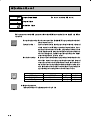
The temperature controller E5EN allows the user to carry out the following:
• Select from many types of temperature, nonĆcontact temperature sensor and analog
input
• Select heating and cooling control in addition to standard control
• Select AT (autoĆtuning) and ST (selfĆtuning) as tuning functions
• Use multiĆSP and the run/stop function according to event input (for units equipped
with the event input function)
• Use the HBA (heater burnout alarm) function (for units equipped with the heater
burnout alarm function)
• Use
the communications function (for units equipped with the communications
function)
• Calibrate sensor input
• The E5EN features a watertight construction (NEMA4X : equivalent to IP66).
• The E5EN conforms to UL/CSA/IEC safety standards and EMC standards.
* This User's Manual describes how to use the E5EN.
Before using your E5EN, thoroughly read and understand this manual in order to
ensure correct use.
Also, store this manual in a safe place so that it can be retrieved whenever necessary.
* For an additional description of the communications function, also refer to the
E5AN/EN/CN/GN
Temperature
Controller,
Communications
Function
User's
Manuals (Cat. No. H102).
E
OMRON, 1999
All rights reserved. No part of this publication may be reproduced, stored in a retrieval system or transmitted,
in any form, or by any means, mechanical, electronic, photocopying, recording, or otherwise, without the prior
written permission of OMRON.
No patent liability is assumed with respect to the use of the information contained herein. Moreover, because
OMRON is constantly striving to improve its highĆquality products, the information contained in this manual is
subject to change without notice. Every precaution has been taken in the preparation of this manual. NevertheĆ
less, OMRON assumes no responsibility for errors or omissions. Neither is any liability assumed for damages
resulting from the use of the information contained in this publication.
I
PRECAUTIONS
When the product is used under the circumstances or environment described in this
manual, always adhere to the limitations of the rating and functions. Also, for safety,
take countermeasures such as fitting fail safe installations.
DO NOT USE :
•
•
In circumstances or environments that have not been described below in this manual.
For control in nuclear power, railway, aircraft, vehicle, incinerator, medical, entertainment,
or safety applications.
•
Where death or serious property damage may occur, or where extensive safety precautions
are required.
II
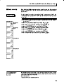
SAFETY PRECAUTIONS
J Safety Signal Words
This manual uses the following signal words to mark safety precautions for the E5EN.
These precautions provide important information for the safe application of the product. You
must be sure to follow the instructions provided in all safety precautions.
WARNING
Indicates information that, if not heeded, could possibly result in loss of life or
CAUTION
Indicates information that, if not heeded, could result in relatively serious or
serious injury.
minor injury, damage to the product, or faulty operation.
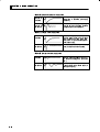
J Safety Precautions
F Electric Shock Warning
CAUTION
Do not touch the terminals while the power is ON.
Doing so may cause an electric shock.
Do not allow metal fragments or lead wire scraps to fall inside this product.
These may cause electric shock, fire or malfunction.
Never disassemble, repair or modify the product.
Doing so may cause electric shock, fire or malfunction.
Do not operate this product in flammable and explosive gas atmospheres.
The life expectancy of the output relays varies greatly with the switching capacity and other switching
conditions. Always use the output relays within their rated load and electrical life expectancy. If an outĆ
put relay is used beyond its life expectancy, its contacts may become fused or burned.
Use this product within the rated load.
Not doing so may cause damage or fire.
Use this product within the rated supply voltage.
Not doing so may cause damage or fire.
Tighten the terminal screws to a torque of 0.74 to 0.90 N m
Loose screws may cause malfunction.
Set all settings according to the control target of the product.
If the settings are not appropriate for the control target, the product may operate in an unexpected manĆ
ner, resulting in damage to the product or resulting in accidents.
To maintain safety in the event of a product malfunction, always take appropriate safety measures, such
as installing an alarm on a separate line to prevent excessive temperature rise.
If a malfunction prevents proper control, a major accident may result.
III
NOTICE
Be sure to observe these precautions to ensure safe use.
(1) Do not wire unused terminals.
(2) Be sure to wire properly with correct polarity of terminals.
(3) To reduce induction noise, separate the highĆvoltage or largeĆcurrent power lines from other lines,
and avoid parallel or common wiring with the power lines when you are wiring to the terminals.
We recommend using separating pipes, ducts, or shielded lines.
(4) Do not use this product in the following places:
• Places subject to dust or corrosive gases (in particular, sulfide gas and ammonia gas)
• Places subject to high humidity, condensation or freezing
• Places subject to direct sunlight
• Places subject to vibration and large shocks
• Places subject to splashing liquid or oily atmosphere
• Places directly subject to heat radiated from heating equipment
• Places subject to intense temperature changes
(5) To allow heat to escape, do not block the area around the product. (Ensure that enough space is
left for the heat to escape.)
• Do not block the ventilation holes on the casing.
(6) When you draw out or draw in the internal mechanism or the terminal unit from the housing,
never touch electrical components inside or subject the internal mechanism to shock.
(7) Cleaning: Do not use paint thinner or the equivalent. Use standard grade alcohol to clean the prodĆ
uct.
(8) Use specified size (M3.5, width 7.2 mm or less) crimped terminals for wiring.
(9) Allow as much space as possible between the E5EN and devices that generate powerful highĆfreĆ
quency noise (e.g. highĆfrequency welders, highĆfrequency sewing machines) or surges.
(10) When executing selfĆtuning, turn the load (e.g. heater) ON simultaneously or before you turn the
the main unit ON. If you turn the the main unit ON before turning the load ON, correct selfĆtuning
results and optimum control may no longer be obtained.
(11) Use a 100 to 240 VAC (50/60 Hz), 24 VAC (50/60 Hz) or 24 VDC power supply matched to the power
specifications of the E5EN. Also, make sure that rated voltage is attained within two seconds of
turning the power ON.
(12) Attach a surge suppressor or noise filter to peripheral devices that generate noise (in particular,
motors, transformers, solenoids, magnetic coils or other equipment that have an inductance comĆ
ponent).
(13) When mounting a noise filter on the power supply, be sure to first check the filter's voltage and
current capacity, and then mount the filter as close as possible to the E5EN.
(14) Use within the following temperature and humidity ranges:
• Temperature: Ć10 to 55_C, Humidity: 25 to 85% (with no icing or condensation)
If the E5EN is installed inside a control board, the ambient temperature must be kept to under
55_C, including the temperature around the E5EN.
If the E5EN is subjected to heat radiation, use a fan to cool the surface of the E5EN to under
55_C.
(15) Store within the following temperature and humidity ranges:
• Temperature: Ć25 to 65_C, Humidity: 25 to 85% (with no icing or condensation)
(16) Never place heavy objects on, or apply pressure to the E5ENasitmaycauseittodeformanddeteriĆ
orate during use or storage.
(17) Avoid using the E5EN in places near a radio, television set, or wireless installation. These devices
can cause radio disturbances which adversely affect the performance of the E5EN.
IV
Conventions Used in This Manual
J Meanings of Abbreviations
The following abbreviations are used in parameter names, figures and in text explanations.
These abbreviations mean the following:
Symbol
Term
PV
Process value
SP
Set point
SV
Set value
AT
AutoĆtuning
ST
SelfĆtuning
EU
Engineering unit *1
*1 EU" stands for Engineering Unit. EU is used as the minimum unit for engineering units
such as C, m, and g.
The size of EU varies according to the input type. For example, when the input temperature
setting range is -200 to +1300 C, 1 EU is 1 C, and when the input temperature setting range
is -20.0 to +500.0 C, 1 EU is 0.1 C.
In the case of analog input, the size of EU varies according to the decimal point position of
the scaling setting, and 1 EU becomes the minimum scaling unit.
_
_
_
_
_
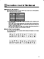
J How to Read Display Symbols
The following tables show the correspondence between the symbols displayed on the displays
and alphabet characters.
A BCDE FGH I J K LM
NOPQR S T UVWXY Z
V
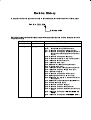
J How This Manual is Organized
Purpose
D Learning about the
Related title
Chapter 1 INTRODUCTION
E5EN
Description
This
chapter
describes
the
features, names of parts and
typical functions.
D Setting up the E5EN
Chapter 2 PREPARATIONS
D Basic operations
Chapter 3 BASIC OPERATION and
These chapters describe basic
Chapter 5 PARAMETERS
control examples.
D Applied operations
Chapter 4 APPLIED OPERATION and
These chapters describe
Chapter 5 PARAMETERS
advanced functions to fully
This chapter describes instalĆ
lation and wiring.
use E5EN.
D Calibration
D Appendix
Chapter 6 CALIBRATION
This
chapter
describes
calĆ
ibration method.
This
chapter
describes
the
unit specifications. There is
also a parameter operations
list to be used as a backup
guide to the parameter setĆ
tings.
VI
Table of Contents
Preface . . . . . . . . . . . . . . . . . . . . . . . . . . . . . . . . . . . . .
Precautions
. . . . . . . . . . . . . . . . . . . . . . . . . . . . . . . . .
Safety Precautions
Notice
1.1
. . . . . . . . . . . . . . . . . . . . . . . . . . .
III
IV
. . . . . . . . . . . . . .
...........................
1Ć1
Names of Parts . . . . . . . . . . . . . . . . . . . . . . . . . . . . . . . . . . . . . . . . . .
1Ć2
Front panel . . . . . . . . . . . . . . . . . . . . . . . . . . . . . . . . . . . . . . . . . . . . . . . . . . . . . . . . .
Display
. . . . . . . . . . . . . . . . . . . . . . . . . . . . . . . . . . . . . . . . . . . . . . . . . . . . . . . . . . . .
How to use keys
1.2
1.3
. . . . . . . . . . . . . . . . . . . . . . . . . . . . . . . . . . . . . . . . . . . . . . . . . . . .
I/O Configuration and Main Functions
I/O configuration
......................
1Ć2
1Ć2
1Ć3
1Ć4
. . . . . . . . . . . . . . . . . . . . . . . . . . . . . . . . . . . . . . . . . . . . . . . . . . . .
1Ć4
Main functions . . . . . . . . . . . . . . . . . . . . . . . . . . . . . . . . . . . . . . . . . . . . . . . . . . . . . .
1Ć5
How Setup Levels Are Configured and Operating
the Keys on the Front Panel . . . . . . . . . . . . . . . . . . . . . . . . . . . . . . .
1.4
1Ć6
Selecting parameters . . . . . . . . . . . . . . . . . . . . . . . . . . . . . . . . . . . . . . . . . . . . . . . .
1Ć8
Fixing settings . . . . . . . . . . . . . . . . . . . . . . . . . . . . . . . . . . . . . . . . . . . . . . . . . . . . . .
1Ć8
................................
1Ć9
CHAPTER 2 PREPARATIONS . . . . . . . . . . . . . . . . . . . . . . . . . . .
2Ć1
2.1
Communications Function
Installation . . . . . . . . . . . . . . . . . . . . . . . . . . . . . . . . . . . . . . . . . . . . . .
Dimensions
2.2
2Ć2
. . . . . . . . . . . . . . . . . . . . . . . . . . . . . . . . . . . . . . . . . . . . . . . . . . . . . . . .
2Ć2
Panel cutout . . . . . . . . . . . . . . . . . . . . . . . . . . . . . . . . . . . . . . . . . . . . . . . . . . . . . . . .
2Ć2
Mounting . . . . . . . . . . . . . . . . . . . . . . . . . . . . . . . . . . . . . . . . . . . . . . . . . . . . . . . . . . .
2Ć3
Draw out . . . . . . . . . . . . . . . . . . . . . . . . . . . . . . . . . . . . . . . . . . . . . . . . . . . . . . . . . . .
2Ć4
Wiring Terminals . . . . . . . . . . . . . . . . . . . . . . . . . . . . . . . . . . . . . . . . .
Terminal arrangement
. . . . . . . . . . . . . . . . . . . . . . . . . . . . . . . . . . . . . . . . . . . . . . .
Precautions when wiring
Wiring
2Ć5
2Ć5
. . . . . . . . . . . . . . . . . . . . . . . . . . . . . . . . . . . . . . . . . . . . .
2Ć5
. . . . . . . . . . . . . . . . . . . . . . . . . . . . . . . . . . . . . . . . . . . . . . . . . . . . . . . . . . . . .
2Ć5
CHAPTER 3 BASIC OPERATION
........................
3Ć1
3.1
Initial Setup Examples . . . . . . . . . . . . . . . . . . . . . . . . . . . . . . . . . . . .
3Ć2
3.2
Setting the Input Type . . . . . . . . . . . . . . . . . . . . . . . . . . . . . . . . . . . .
3Ć4
Input type . . . . . . . . . . . . . . . . . . . . . . . . . . . . . . . . . . . . . . . . . . . . . . . . . . . . . . . . . .
3.3
Selecting
_C/_F
.........................................
Temperature unit . . . . . . . . . . . . . . . . . . . . . . . . . . . . . . . . . . . . . . . . . . . . . . . . . . . .
3Ć4
3Ć5
3Ć5
3.4
Selecting PID Control or ON/OFF Control . . . . . . . . . . . . . . . . . . .
3Ć6
3.5
Setting Output Specifications . . . . . . . . . . . . . . . . . . . . . . . . . . . . . .
3Ć7
Control period
3.6
. . . . . . . . . . . . . . . . . . . . . . . . . . . . . . . . . . . . . . . . . . . . . . . . . . . . . .
3Ć7
Direct/reverse operation . . . . . . . . . . . . . . . . . . . . . . . . . . . . . . . . . . . . . . . . . . . . . .
3Ć7
Setting the SP . . . . . . . . . . . . . . . . . . . . . . . . . . . . . . . . . . . . . . . . . . .
3Ć9
Changing the SP . . . . . . . . . . . . . . . . . . . . . . . . . . . . . . . . . . . . . . . . . . . . . . . . . . . .
3.7
Executing ON/OFF Control . . . . . . . . . . . . . . . . . . . . . . . . . . . . . . . .
ON/OFF Control
II
. . . . . . . . . . . . . . . . . . . . . . . . . . . . . . . . . . . . . .
Conventions Used in This Manual
CHAPTER 1 INTRODUCTION
I
3Ć9
3Ć10
. . . . . . . . . . . . . . . . . . . . . . . . . . . . . . . . . . . . . . . . . . . . . . . . . . . .
3Ć10
Setup . . . . . . . . . . . . . . . . . . . . . . . . . . . . . . . . . . . . . . . . . . . . . . . . . . . . . . . . . . . . . .
3Ć11
V
3.8
3.9
Determining PID Constants (AT, ST, manual setup) . . . . . . . . . . .
3Ć12
AT.(autoĆtuning) . . . . . . . . . . . . . . . . . . . . . . . . . . . . . . . . . . . . . . . . . . . . . . . . . . . . .
3Ć12
ST (selfĆtuning) . . . . . . . . . . . . . . . . . . . . . . . . . . . . . . . . . . . . . . . . . . . . . . . . . . . . .
3Ć13
ST start conditions . . . . . . . . . . . . . . . . . . . . . . . . . . . . . . . . . . . . . . . . . . . . . . . . . .
3Ć14
ST stable range . . . . . . . . . . . . . . . . . . . . . . . . . . . . . . . . . . . . . . . . . . . . . . . . . . . . .
3Ć14
Manual setup . . . . . . . . . . . . . . . . . . . . . . . . . . . . . . . . . . . . . . . . . . . . . . . . . . . . . . .
3Ć15
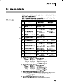
Alarm Outputs . . . . . . . . . . . . . . . . . . . . . . . . . . . . . . . . . . . . . . . . . . .
3Ć17
Alarm type . . . . . . . . . . . . . . . . . . . . . . . . . . . . . . . . . . . . . . . . . . . . . . . . . . . . . . . . .
3Ć17
Alarm value . . . . . . . . . . . . . . . . . . . . . . . . . . . . . . . . . . . . . . . . . . . . . . . . . . . . . . . .
3Ć18
3.10 Heater Burnout Alarm (HBA) . . . . . . . . . . . . . . . . . . . . . . . . . . . . . .
3Ć19
HBA detection . . . . . . . . . . . . . . . . . . . . . . . . . . . . . . . . . . . . . . . . . . . . . . . . . . . . . .
3Ć19
Operating conditions . . . . . . . . . . . . . . . . . . . . . . . . . . . . . . . . . . . . . . . . . . . . . . . . .
3Ć19
Setup . . . . . . . . . . . . . . . . . . . . . . . . . . . . . . . . . . . . . . . . . . . . . . . . . . . . . . . . . . . . . .
3Ć20
How to calculate detection current values . . . . . . . . . . . . . . . . . . . . . . . . . . . . . . .
3Ć21
Example . . . . . . . . . . . . . . . . . . . . . . . . . . . . . . . . . . . . . . . . . . . . . . . . . . . . . . . . . . .
3Ć21
3.11 Requests during Operation . . . . . . . . . . . . . . . . . . . . . . . . . . . . . . . .
3Ć22
CHAPTER 4 APPLIED OPERATION . . . . . . . . . . . . . . . . . . . . . .
4Ć1
4.1
4.2
Shifting Input Values
4.4
4.5
4.6
4Ć2
How to calculate input shift values (2Ćpoint shift) . . . . . . . . . . . . . . . . . . . . . . . . .
4Ć3
1Ćpoint shift method . . . . . . . . . . . . . . . . . . . . . . . . . . . . . . . . . . . . . . . . . . . . . . . . .
4Ć4
2Ćpoint shift method . . . . . . . . . . . . . . . . . . . . . . . . . . . . . . . . . . . . . . . . . . . . . . . . .
4Ć4
Example of 2Ćpoint temperature input shift . . . . . . . . . . . . . . . . . . . . . . . . . . . . . .
4Ć5
Alarm Hysteresis
........................................
4Ć6
..................................................
4Ć6
Alarm latch . . . . . . . . . . . . . . . . . . . . . . . . . . . . . . . . . . . . . . . . . . . . . . . . . . . . . . . . .
4Ć6
Close in alarm/open in alarm . . . . . . . . . . . . . . . . . . . . . . . . . . . . . . . . . . . . . . . . . .
4Ć7
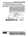
Setting Scaling Upper and Lower Limits (analog input) . . . . . . . .
4Ć8
Analog input . . . . . . . . . . . . . . . . . . . . . . . . . . . . . . . . . . . . . . . . . . . . . . . . . . . . . . . .
4Ć8
Executing Heating and Cooling Control . . . . . . . . . . . . . . . . . . . . .
4Ć10
Heating and cooling control . . . . . . . . . . . . . . . . . . . . . . . . . . . . . . . . . . . . . . . . . . .
4Ć10
Setup . . . . . . . . . . . . . . . . . . . . . . . . . . . . . . . . . . . . . . . . . . . . . . . . . . . . . . . . . . . . . .
4Ć11
To Use Event Input . . . . . . . . . . . . . . . . . . . . . . . . . . . . . . . . . . . . . . .
4Ć12
Setting event input . . . . . . . . . . . . . . . . . . . . . . . . . . . . . . . . . . . . . . . . . . . . . . . . . .
4Ć12
How to use multiĆSP . . . . . . . . . . . . . . . . . . . . . . . . . . . . . . . . . . . . . . . . . . . . . . . . .
4Ć12
Setting by key operation
4Ć13
.............................................
Setup . . . . . . . . . . . . . . . . . . . . . . . . . . . . . . . . . . . . . . . . . . . . . . . . . . . . . . . . . . . . . .
4Ć13
Executing run/stop control . . . . . . . . . . . . . . . . . . . . . . . . . . . . . . . . . . . . . . . . . . . .
4Ć14
Setting the SP Upper and Lower Limit Values
Set point limitter
4.7
4Ć2
Shifting input . . . . . . . . . . . . . . . . . . . . . . . . . . . . . . . . . . . . . . . . . . . . . . . . . . . . . . .
Standby sequence
4.3
.....................................
...............
4Ć15
....................................................
4Ć15
Setup . . . . . . . . . . . . . . . . . . . . . . . . . . . . . . . . . . . . . . . . . . . . . . . . . . . . . . . . . . . . . .
4Ć16
Executing the SP Ramp Function
(limiting the SP change rate) . . . . . . . . . . . . . . . . . . . . . . . . . . . . . .
SP ramp . . . . . . . . . . . . . . . . . . . . . . . . . . . . . . . . . . . . . . . . . . . . . . . . . . . . . . . . . . .
4Ć17
4Ć17
4.8
To Move to the Advanced Function Setting Level
............
4Ć19
4.9
Using the Key Protect Level . . . . . . . . . . . . . . . . . . . . . . . . . . . . . . .
4Ć20
Key protect . . . . . . . . . . . . . . . . . . . . . . . . . . . . . . . . . . . . . . . . . . . . . . . . . . . . . . . . .
4Ć20
CHAPTER 5 PARAMETERS . . . . . . . . . . . . . . . . . . . . . . . . . . . . .
Conventions Used in this Chapter
5Ć1
..............................
5Ć2
Protect Level . . . . . . . . . . . . . . . . . . . . . . . . . . . . . . . . . . . . . . . . . . . . . . . . .
5Ć3
Operation Level . . . . . . . . . . . . . . . . . . . . . . . . . . . . . . . . . . . . . . . . . . . . . .
5Ć4
Adjustment Level . . . . . . . . . . . . . . . . . . . . . . . . . . . . . . . . . . . . . . . . . . . . .
5Ć11
Initial Setting Level
...........................................
5Ć19
Advanced Function Setting Level . . . . . . . . . . . . . . . . . . . . . . . . . . . . . . .
5Ć27
Communications Setting Level . . . . . . . . . . . . . . . . . . . . . . . . . . . . . . . . .
5Ć43
CHAPTER 6 CALIBRATION . . . . . . . . . . . . . . . . . . . . . . . . . . . . .
6Ć1
6.1
Parameter Structure
.....................................
6Ć2
6.2
User Calibration . . . . . . . . . . . . . . . . . . . . . . . . . . . . . . . . . . . . . . . . .
6Ć3
6.3
Calibrating Thermocouples . . . . . . . . . . . . . . . . . . . . . . . . . . . . . . . .
6Ć4
6.4
Calibrating Analog Input . . . . . . . . . . . . . . . . . . . . . . . . . . . . . . . . . .
6Ć7
6.5
Calibrating Platinum Resistance Thermometers
.............
6Ć8
6.6
Checking Indication Accuracy . . . . . . . . . . . . . . . . . . . . . . . . . . . . .
6Ć9
APPENDIX . . . . . . . . . . . . . . . . . . . . . . . . . . . . . . . . . . . . . . . . . . . . .
AĆ1
SPECIFICATIONS . . . . . . . . . . . . . . . . . . . . . . . . . . . . . . . . . . . . . . . . . . . .
AĆ2
Ratings . . . . . . . . . . . . . . . . . . . . . . . . . . . . . . . . . . . . . . . . . . . . . . . . . . . . . . . . . . . .
AĆ2
Characteristics . . . . . . . . . . . . . . . . . . . . . . . . . . . . . . . . . . . . . . . . . . . . . . . . . . . . . .
AĆ3
CURRENT TRANSFORMER (CT) . . . . . . . . . . . . . . . . . . . . . . . . . . . . . .
AĆ4
ERROR DISPLAY . . . . . . . . . . . . . . . . . . . . . . . . . . . . . . . . . . . . . . . . . . . .
AĆ5
PARAMETER OPERATIONS LIST . . . . . . . . . . . . . . . . . . . . . . . . . . . . . .
AĆ7
SENSOR INPUT SETTING AND INDICATION RANGES
..........
AĆ11
SETUP LEVELS DIAGRAM . . . . . . . . . . . . . . . . . . . . . . . . . . . . . . . . . . . .
AĆ12
PARAMETER FLOW . . . . . . . . . . . . . . . . . . . . . . . . . . . . . . . . . . . . . . . . . .
AĆ14
INDEX
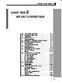
CHAPTER 1 INTRODUCTION
1
CHAPTER 1
INTRODUCTION
1.1
Names of Parts
. . . . . . . . . . . . . . . . . . . . . . . .
1Ć2
. . . . . . . . . . . . . . . . . . . . . . . . . . .
1Ć2
. . . . . . . . . . . . . . . . . . . . . . . . . . . . . . .
1Ć2
Front panel
Display
How to use keys
1.2
1.3
1.4
. . . . . . . . . . . . . . . . . . . . . . .
1Ć3
I/O Configuration and Main Functions . . .
1Ć4
I/O configuration . . . . . . . . . . . . . . . . . . . . . . .
1Ć4
Main functions
1Ć5
. . . . . . . . . . . . . . . . . . . . . . . .
How Setup Levels Are Configured and
Operating the Keys on the Front Panel . . .
1Ć6
Selecting parameters
. . . . . . . . . . . . . . . . . . .
1Ć8
Fixing settings . . . . . . . . . . . . . . . . . . . . . . . . .
1Ć8
Communications Function . . . . . . . . . . . . . .
1Ć9
1-1
CHAPTER 1 INTRODUCTION
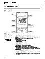
1.1
J
Names of Parts
Front panel
Temperature
unit
No.1 display
Operation
indicators
No.2 display
Mode key
Level key
J
Down key
Display
F
F
F
No.1 display
No.2 display
Operation
indicators
1-2
Up key
#*($0* +" ()'** -$, ') ()%+) +0(
#!"+* ') (()'/#%+$0 '& *'& ,)#&! *+)+,(
#*($0* +" *+ ('#&+ ()%+) '()+#'& ) -$, ') +" %&#(,$+
-)#$
#!"+* ') (()'/#%+$0 '& *'& ,)#&! *+)+,(
$)% #!"+* ."& $)% #* $)% #!"+* ."& $)% #* $)% #!"+* ."& $)% #* "+) ,)&',+ $)% #*($0
#!"+* ."& "+) ,)&',+ #* ++
'&+)'$ ',+(,+ '&+)'$ ',+(,+ #!"+* ."& '&+)'$ ',+(,+ &') '&+)'$ ',+(,+ ) '.3
-) ."&-) '&+)'$ ',+(,+ #* +" ,))&+ ',+(,+ *+0* ' *+'(
#!"+* ."& '()+#'& #* *+'((
,)#&! '()+#'& +"#* #&#+') $#!"+* ."& & -&+ ') +" ),&*+'(
,&+#'& #* *+'((
'%%,&#+#'&* .)#+#&! '&+)'$
#!"+* ."& '%%,&#+#'&* .)#+#&! #* 1&$ & #* ',+ ."& #+
#* 1#*$
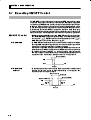
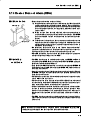
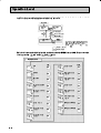
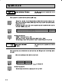
1.1 Names of Parts
F
Temperature unit
The temperature unit is displayed when the display unit parameter is set
to a temperature. Indication is determined by the currently selected temĆ
perature unit" parameter set value. When this parameter is set to _C",
" is displayed, and when set to _F", " is displayed.
Flashes during ST operation.
J
How to use keys
F
F
F
F
F
The following describes the basic functions of the front panel keys.
(level) key
Press this key to select the setting levels. The setting level is selected in
order operation level" ←→ adjustment level", initial setting level" ←→
communications setting level".
(mode) key
Press this key to select parameters within each level.
(up) key
Each press of this key increases values displayed on the No.2 display. HoldĆ
ing down this key speeds up the incrementation.
(down) key
Each press of this key decreases values displayed on the No.2 display. HoldĆ
ing down this key speeds up the decrementation.
+
key
combination
This key combination sets the E5EN to the protect level." For details on
the protect level, see Chapter 5 Parameters.
1-3
CHAPTER 1
1.2
J
INTRODUCTION
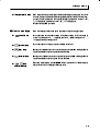
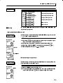
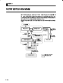
I/O Configuration and Main Functions
I/O configuration
OUT1
Control output 1
Temperature input/
analog input
Control output 1
Control output 2
HBA
Heating and
cooling
CT input
Standard
*
Alarm output 3
ALM3
Alarm 3
Event input 2ch
Controller
SP input from external
digital switch function and
Run/Stop function
OUT2
Alarm 2
Alarm 1
HBA
Input error
Communications
function
1-4
ALM2
Alarm output 2
ALM1
HB
Alarm output 1
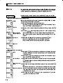
1.2 I/O Configuration and Main Functions
J Main functions
F Input sensor
types
F Control output
#.+ ,3003;/2- /2863*9)+7 8.+ 1'/2 ,92)8/327 3, 8.+ 36 *+8'/07 32
+'). ,92)8/32 '2* .3; 83 97+ 8.+ ,92)8/327 7++ .'48+6 32;'6*7
• #.+ ,3003;/2- /2498 7+27367 )'2 (+ )322+)8+* ,36 8+14+6'896+ /2498
#.+613)3940+
# $ ! " 32A)328')8 8+14+6'896+ 7+2736 8=4+ "
83 _ 83 _ 83 _
83 _
0'8/291 6+7/78'2)+ 8.+6131+8+6
8
8
2'03- /2498
83 1%
• 328630 398498 /7 +/8.+6 6+0'= :308'-+ 36 )966+28 398498 *+4+2*/2- 32
8.+ 13*+0 3, j jjj
• , .+'8/2- '2* )330/2- )328630 /7 7+0+)8+* 32 8.+ A '0'61
398498 /7 97+* '7 )330/2- 7/*+ 398498 #.+6+,36+ 97+ '0'61 /, '2
'0'61 /7 2++*+* /2 .+'8/2- '2* )330/2- )328630
F Alarms
• "+8 8.+ '0'61 8=4+ '2* '0'61 :'09+ 36 944+6A '2* 03;+6A0/1/8 '0'617
• , 2+)+77'6= ' 136+ )3146+.+27/:+ '0'61 ,92)8/32 )'2 (+ ')./+:+* (=
7+88/2- 8.+ >78'2*(= 7+59+2)+ >'0'61 .=78+6+7/7 '2* >)037+ /2 '0'61
34+2 /2 '0'61 '2* '0'61 0'8). 4'6'1+8+67
• &.+2 8.+ /2498 +6636 398498 /7 7+8 83 > '0'61 398498 89627 ;.+2 '2 /2498 +6636 3))967
F Control
adjustment
F Event input
F HBA
F Communications
function
• 48/191 )3278'287 )'2 (+ 7+8 +'7/0= (= # '983A892/2- '2* "#
7+0,A892/2-
• &.+2 +59/44+* ;/8. 8.+ 348/32 +:+28 /2498 92/8 A 8.+ ,3003;/2,92)8/327 )'2 (+ ')./+:+* (= +:+28 /2498
"+8 43/28 7+0+)8/32 1908/A" 1'< 43/287 '2* 6927834
• #.+ .+'8+6 (962398 '0'61 ,92)8/32 /7 7944368+* ;.+2 8.+ 348/32
92/8 AA
36 A /7 13928+* /2 8.+ • 3143&'= '2* "=7;'= )31192/)'8/327 '6+ 7944368+* ;.+2 8.+
348/32 )31192/)'8/327 92/8 A
36 A /7 13928+* /2 8.+
3143&'= /7 ' -+2+6'0A496437+ 7+6/'0 )31192/)'8/327A('7+* 92/A
,/+* )31192/)'8/327 463)+*96+ *+:+034+* (= ! 3143&'= 97+7
)311'2*7 )3140/'28 ;/8. 8.+ ;+00A+78'(0/7.+* " 83-+8.+6 ;/8. ' 92/A
,/+* ,6'1+ ,361'8 32 ! 463-6'11'(0+ )3286300+67 83 ,')/0/8'8+
)31192/)'8/327 (+8;++2 4+6732'0 )31498+67 '2* )31432+287
"=7;'= )31192/)'8/32 *3+7 238 7944368 '0'61 398498
1-5
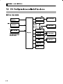
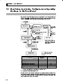
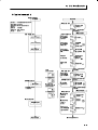
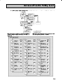
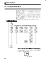
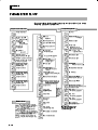
1.3
How Setup Levels Are Configured and Operating
the Keys on the Front Panel
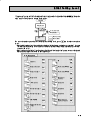
Parameters are divided into groups, each called a level". Each of the set
values (setup items) in these levels are called a parameter." The parameĆ
ters on the E5EN are divided into the following seven levels:
+2!- ,!-/%+* (!1!(
&0./)!*/ (!1!(
'!3
'!3
.!+*
!.. /$*
.!+*
$! "(.$!.
)%*
'!3
%.,(3
'!3 .!+* . )%*
'!3
.!+*
'!3
)%*
$! %.,(3 "(.$!. "/!- +*! .!+* +*/-+( ./+,.
'!3
.!+* . )%*
+))08
*%/%+*.
*%/%( .!//%*# (!1!(
'!3
-+/!/ (!1!(
.!//%*# (!1!(
!.. /$*
.!+*
..2+-
'!3
.!+*
)%*
$! '!3 ,-!..%*# /%)! *
!$*#!
%*,0/
)+1!
.!/ 1(0! 4
%* ,-+/!/ (!1!(
/%)!
1*!
"0*/%+* (!1!(
1*!
"0*/%+* .!//%*# (!1!(
..2+-
%*,0/
.!/ 1(0! 4
+*/-+( %* ,-+#-!..
(%-/%+* (!1!(
+*/-+( ./+,,!
Control in
Progress
-+/!/ (!1!(
,!-/%+* (!1!(
&0./)!*/ (!1!(
*
f
f
f
*%/%( .!//%*# (!1!(
8
1*!
8
"0*/%+* .!//%*# (!1!(
(%-/%+* (!1!(
8
+))0*%/%+*. .!//%*# (!1!(
8
Control Stopped
8
8
8
f
f
f
f
* : To activate the advanced function setting level, set the Protect level"
of the Initial/Communications protect" to 0".
: Indicates items that can be set.
f
Of these levels, the initial setting level, communications setting level,
advanced function setting level and calibration level can be used only
when control has stopped. Note that controller outputs are stopped when
any of these four levels are selected.
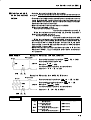
1.3 How Setup Levels Are Configured and Operating the Keys on the Front Panel
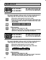
F Protect level
F Operation level
F Adjustment level
F Initial setting
level
F Advanced
function setting
level
F Communications
setting level
F Calibration level
• + )+2! 0$! )+ ! 0 0$%/ (!2!( /%)1(0*!+1/(4 ,.!// 0$!
*
'!4/ "+. 0 (!/0 0$.!! /!+* / %* 0$! +,!.0%+* (!2!( +. &1/0)!*0 (!2!(
$%/ (!2!( %/ "+. ,.!2!*0%*# 1*3*0! +. % !*0( )+ %"%0%+* +"
,.)!0!./ .+0!0! (!2!(/ 3%(( *+0 ! %/,(4! * /+ 0$! ,.)!7
0!./ %* 0$0 (!2!( **+0 ! )+ %"%! • $%/ (!2!( %/ %/,(4! 3$!* 01.*%*# 0$! ,+3!. " * ! )+2! 0+
0$! ,.+0!0 (!2!( %*%0%( /!00%*# (!2!( * &1/0)!*0 (!2!( ".+) 0$%/
(!2!(
• +.)((4 /!(!0 0$%/ (!2!( 1.%*# +,!.0%+* 1.%*# +,!.0%+* 0$! ,.+7
!// 2(1! * )*%,1(0! 2.%(! * ! )+*%0+.! * 0$! /!0 ,+%*0
(.) 2(1! * 1,,!.7 * (+3!.7(%)%0 (.)/ * ! )+*%0+.! *
)+ %"%! • + )+2! 0$! )+ ! 0 0$%/ (!2!( ,.!// 0$!
'!4 "+. (!// 0$* +*!
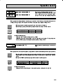
/!+* • $%/ (!2!( %/ "+. !*0!.%*# /!0 2(1!/ * +""/!0 2(1!/ "+. +*0.+( $%/
(!2!( +*0%*/ ,.)!0!./ "+. /!00%*# 0$! 10+701*%*# +))1*%7
0%+*/ 3.%0%*# !*(! %/(! $4/0!.!/%/ )1(0%7 %*,10 /$%"0 2(1!/
$!0!. 1.*+10 (.) * +*/0*0/ " * ! )+2! 0+ 0$!
0+, ,.)!0!. +" 0$! %*%0%( /!00%*# (!2!( ,.+0!0 (!2!( * +,!.0%+*
(!2!( ".+) $!.!
• + )+2! 0$! )+ ! 0 0$%/ (!2!( ,.!// 0$!
'!4 "+. 0 (!/0 0$.!!
/!+* / %* 0$! +,!.0%+* (!2!( +. &1/0)!*0 (!2!( $! %/,(4
"(/$!/ "0!. +*! /!+* $%/ (!2!( %/ "+. /,!%"4%*# 0$! %*,10 04,! /!(!07
%*# 0$! +*0.+( )!0$+ +*0.+( ,!.%+ /!00%*# %.!0.!2!./! 0%+* *
(.) 04,! " * ! )+2! 0+ 0$! 2*! "1*0%+* /!00%*# (!2!( +.
+))1*%0%+*/ /!00%*# (!2!( ".+) 0$%/ (!2!( + .!01.* 0+ 0$! +,!.0%+*
(!2!( ,.!// 0$!
'!4 "+. 0 (!/0 +*! /!+* + )+2! 0+ 0$! +))17
*%0%+*/ /!01, (!2!( ,.!// 0$!
'!4 "+. (!// 0$* +*! /!+* • + 0%20! 0$! 2*! "1*0%+* /!00%*# (!2!( "0!. /!00%*# 0$! 5.+7
0!0 (!2!( +" 0$! 5*%0%(+))1*%0%+*/ ,.+0!0 0+ 5 %*,10 0$!
,//3+. 5
%* 0$! %*%0%( /!00%*# (!2!(
• " * ! )+2! 0+ 0$! (%.0%+* (!2!( +. %*%0%( (!2!( ".+) 0$%/ (!2!(
• $%/ (!2!( %/ "+. /!00%*# 0$! 10+)0% .!01.* +" %/,(4 )+ ! (%)%07
0!. !2!*0 %*,10 //%#*)!*0 /0* 4 /!-1!*! (.) $4/0!.!/%/ /!("701*%*# * "+. )+2%*# 0+ 0$! 1/!. (%.0%+* (!2!(
• + )+2! 0$! )+ ! 0 0$%/ (!2!( ,.!// 0$!
'!4 "+. (!// 0$* +*! /!+*
%* 0$! %*%0%( /!00%*# (!2!( $!* 0$! +))1*%0%+*/ "1*0%+* %/ 1/! /!0 0$! +))1*%0%+*/ +* %0%+*/ %* 0$%/ (!2!( +))1*%0%*# 3%0$ ,!./+*( +),10!. $+/0 +),10!. ((+3/ /!0 ,+%*0/ 0+ ! .! * 3.%07
0!* * )*%,1(0! 2.%(!/ 0+ ! )+*%0+.! • + )+2! 0$! )+ ! 0 0$%/ (!2!( !*0!. 0$! ,//3+. 5
%* 0$!
2*! "1*0%+* /!00%*# (!2!( $%/ (!2!( %/ "+. +""/!00%*# !2%0%+* %*
0$! %*,10 %.1%0
• " * *+0 ! )+2! 0+ +0$!. (!2!(/ 4 +,!.0%*# 0$! '!4/ +* 0$! ".+*0
,*!( ".+) 0$! (%.0%+* (!2!( + *!( 0$%/ (!2!( 01.* 0$! ,+3!. 0$!* ' #%*
1-7
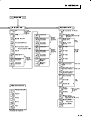
CHAPTER 1 INTRODUCTION
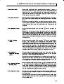
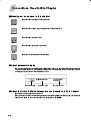
J Selecting
•
parameters
$ ! $ ! # Parameter
1
Parameter
2
Parameter
3
Parameter
n
J Fixing settings
•
$ $ !
•
$ •
$ ! " $ # ! $
#
•
" # $ $ &
$ $ 1-8
$
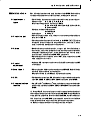
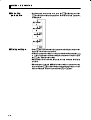
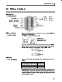
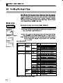
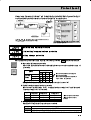
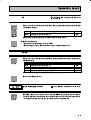
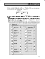
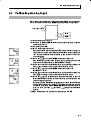
1.4 Communications Function
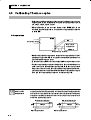
1.4
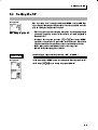
Communications Function
The E5EN can be provided with a communications function that allows you
to check and set controller parameters on a host computer. If the communicaĆ
tions function is required, mount the option unit (E5EN01 or
E5EN03 ) in the E5EN. For details on the communications function,
see the separate Communications Functions User's Manual."
Follow the procedure below to move to the communications setting level.
VVV V
VVV V
(1) Press the
key for at least three seconds in the operation level".
The level moves to the initial setting level".
key for less than one second. The initial setting level"
(2) Press the
moves to the communications setting level".
(3) Pressing the
key advances the parameters as shown in the followĆ
ing figure.
(4) Press the
or
keys to change the parameter setups.
Communications
unit No.
Baud rate
Data bit
Stop bit
Parity
F
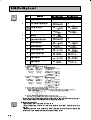
Setting up
communications
data
Parameter
Set the E5EN communications specifications so that they match the comĆ
munications setup of the host computer. In a multidrop 1:N configuration,
match the setting data except the communications unit No. on all units.
Unique communications unit Nos. must be set to each unit.
Displayed
Characters
Set (monitor) Value
Settings
Default
Unit
1
None
9.6
kbps
Communications unit No.
0 to 99
Baud rate
1.2, 2.4, 4.8, 9.6, 19.2
Data bit
7, 8
7
bit
Stop bit
1, 2
2
bit
Parity
None, even, odd
Even
None
. , . , . ,
,
. ,
,
.
1-9
CHAPTER 2 PREPARATIONS
2
CHAPTER 2
PREPARATIONS
2.1
2.2
Installation . . . . . . . . . . . . . . . . . . . . . . . . . . . .
2Ć2
Dimensions . . . . . . . . . . . . . . . . . . . . . . . . . . . .
2Ć2
Panel cutout . . . . . . . . . . . . . . . . . . . . . . . . . . .
2Ć2
Mounting
. . . . . . . . . . . . . . . . . . . . . . . . . . . . .
2Ć3
Draw out . . . . . . . . . . . . . . . . . . . . . . . . . . . . . .
2Ć4
Wiring Terminals
2Ć5
. . . . . . . . . . . . . . . . . . . . . .
Terminal arrangement
. . . . . . . . . . . . . . . . .
Precautions when wiring
2Ć5
. . . . . . . . . . . . . . .
2Ć5
Wiring . . . . . . . . . . . . . . . . . . . . . . . . . . . . . . . .
2Ć5
2-1
CHAPTER 2
2.1
J
PREPARATIONS
Installation
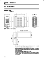
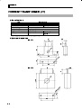
Dimensions
(Unit: mm)
99.4
44
Panel cutout
91
112
96
Unit: mm
number of units Ć2.5)
+1.0
0
+0.6
92
-0
45 - 0
+0.8
120 min.
92
+0.8
(48
-0
J
78
93.3
11.5
48
•
Several units cannot be group mounted close together vertically.
(Observe the recommended mounting space limits.)
•
When group mounting several controllers, ensure that the surrounding
temperature does not exceed the allowable operating temperature listed
in the specifications.
•
The recommended panel thickness is 1 to 8 mm.
•
To ensure waterproofing, enclose the unit in the waterproof packing
prior to mounting. Waterproofing is not possible when group mounting
several units.
2-2
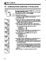
2.1 Installation
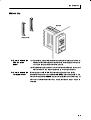
J Mounting
Adaptor
Terminal cover
F How to attach the
E5EN on the
panel
(1) Insert the main unit through the mounting hole in the panel (1Ć8 mm
thickness). Pull the adapter along the body of the main unit from rear
case up to the panel and fasten temporarily.
(2) Tighten the upper and lower screws alternately with only one turn of
the screwdriver at a time to maintain an even torque balance.
F How to attach the
terminal cover
Fit terminal cover E53-COV11 onto the upper and lower hooks.
Attach the terminal cover so that the OMRON mark of terminal Nos.1 to
10 faces down and the OMRON mark of terminal Nos.11 to 18 faces up. If
the cover is attached the other way round, the fixture can no longer be
attached.
2-3
CHAPTER 2
PREPARATIONS
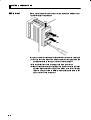
J Draw out
The main unit can be drawn out to perform maintenance without removĆ
ing the terminal compartment.
(1)
(2)
(3)
Prepare a screwdriver that can be used on the lower front screw of the unit.
(1) Loosen the lower front screw with a screwdriver (turning left) while
pushing the hook on the upper surface of the front panel.
(2) Grasp both sides of the front panel and draw (pull) it out.
(3) Ensure that the waterproof packing is in place before drawing in the
unit. ReĆtighten the lower front screw with a screwdriver (turning
right) to a torque of 0.3 to 0.5 Nm while pushing the hook on the
upper surface of the front panel.
2-4
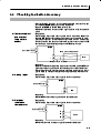
2.2 Wiring Terminals
2.2
J
Wiring Terminals
Terminal
arrangement
AC/DC 24V (No polarity)
Relay output
Voltage output/
AC250V 5A
DC12V 40mA
(Resistive load)
Current output
Input power
OUT1
1
11
2
12
3
13
4
14
5
15
6
16
7
17
8
18
EV2
Alarm output
(Resistive load)
ALM2
9
ALM1/Heater burnout/Input error
J
Precautions
when wiring
•
RSĆ485
11
SD
11
B (+)
12
RD
12
A (-)
13
SG
13
Do not
use
CT
A
B
B
TC
Analog input
Pt
10
(*, #&(-, $+ & ('/* $#&+ #& '** ,' (*',, ," &
#,+ $#&+
•
EV1
EV1
EV2
ALM3/OUT2
AC250V 3A
RSĆ232C
Event input
AC100V to 240V
*'% 0,*&$ &'#+
+ '* $*!* ,/#+, (#* $
AWG28 or larger
Conductor crossĆsection
0.08042mm2 or larger
•
•
•
,+ *'%%& ,' -+ +'$*$++ ,*%#&$+ /"& /#*#&! ," #!",& ," ,*%#&$ +*/+ -+#&! ,'*)- &' !*,* ,"& %
+ ,"
'$$'/#&! ,1( '
+'$*$++ ,*%#&$+
'* +*/+
7.2 mm max.
7.2 mm max.
J
Wiring
F
Power supply
•
'&&, ,' ,*%#&$ '+ & " '$$'/#&! ,$ +"'/+ ," +(# #3
,#'&+
Input power supply
E5EN
100 to 240 VAC, 50/60 Hz
9VA
24 VAC, 50/60 Hz
5VA
24 VDC (no polarity)
4W
•
,&* #&+-$,#'& #+ (($# ,' ," ('/* +-(($1 +,#'&+ *#&3
'* #&+-$,#'& #+ *)-#* '&&, ," #&(-, & '-,(-, ,*%#&$+ ,'
.# /#,"'-, &1 0('+ -**&,3**1#&! (*,+ '* ,' .# /#,"
+,&* #&+-$,#'& +-#,$
'* ," %0#%-% '(*,#&! .'$,! '
,"
('/* +-(($1 +,#'&
2-5
#! ! !#"
F
F
Input
• ,++#!1 1, 1#/*'+) ,0
1, 0 $,)),40 !!,/"'+% 1, 1&# '+-21 15-#
=
=8
#-*402(273/* /&6.170 4*5.56&1(* 1&/2,
6-*4020*6*4
.1376
Control output 1
• #/*'+) ,0 1, /# $,/ !,+1/,) ,21-21 &# $,)),4'+% "'%/*0
0&,4 1&# 3') )# ,21-210 +" 1&#'/ '+1#/+) #.2)'6'+% !'/!2'10
%
%
!*/&;
%2/6&,*
744*16
• &# $,)),4'+% 1 )# 0&,40 1&# 0-#!'$'!1',+0 $,/ #!& ,21-21 15-#
Output type
Specifications
!*/&;
% 4*5.56.8* /2&) */*(64.(&/ /.+* 23*4&6.215
%2/6&,* 9.6- 5-246=(.4(7.6 % 0 0&:
3426*(6.21
744*16
0 /2&) Ω 0&: 4*52/76.21 &3342: • &# 3,)1%# ,21-21 !,+1/,) ,21-21 '0 +,1 #)#!1/'!))5 '+02)1#" $/,* 1&#
'+1#/+) !'/!2'10 &#+ 20'+% %/,2+"'+% 1&#/*,!,2-)# ", +,1 !,++#!1
1&# !,+1/,) ,21-21 1#/*'+)0 1, 1&# %/,2+" $ 1&# !,+1/,) ,21-21 1#/*'9
+)0 /# !,++#!1#" 1, 1&# %/,2+" #//,/0 4')) ,!!2/ '+ 1&# *#02/#" 1#*9
-#/12/# 3)2#0 0 /#02)1 ,$ )#(%# !2//#+1
F
Alarm
output/Control
output 2
V VVV
• + 1&# 9 )/* ,21-21 '0 #14##+ 1#/*'+) ,0
+" )/* ,21-21 '0 #14##+ 1#/*'+) ,0 +" +"
)/* ,21-21 '0 #14##+ 1#/*'+) ,0 +" &#+ 21')'6'+%
'+% +" !,,)'+% !,+1/,) )/* ,21-21 #!,*#0 )/* ,21-21 +"
)/* ,21-21 '0 +,1 3') )#
&#+ 1&# '+-21 #//,/ ,21-21 '0 0#1 1, 7 )/* ,21-21 12/+0 4&#+ + '+-21 #//,/ ,!!2/0
• &#+ 1&# ,-1',+ 2+'1 9
,/ '0 *,2+1#" ,+ 1&#
+ ,$ )/* ,21-21 +" 1&# #/ 2/+,21 )/* 4')) #
,21-21 , "'0 )# )/* ,21-21 +" ,21-21 ,+)5 1&# #/ 2/+,21
)/* ,+ 1#/*'+)0 +" 0#1 1&# *,"# ,$ 1&# )/* ,21-21 1, • &# '+1#/',/ #.2'3)#+1 !'/!2'10 ,$ )/* ,21-21 +" /# 0&,4+ '+
1&# $,)),4'+% "'%/*
$#
*&6*4'741276 &/&401376 *4424
2.2 Wiring Terminals
•
$/ *(# #+#'&* ) * '$$'.*
2
F
CT input
•
"& +" '(+#'& ,&#+ 2 ') 2 #* %',&+ '& +" & +" "+) ,)&',+ ,&+#'& #* ,* '&&+ ,))&+ +)&* ')%)
)'** +)%#&$ '* & 14
CT
15
F
E5ENĆVVHVV
Event input
•
"& +" '(+#'& -&+ #&(,+ ,&#+ 2 #* %',&+ '& +" & -&+ #&(,+ #* ,* '&&+ +' +)%#&$ '* +' 11
EV1
12
EV2
13
•
* -&+ #&(,+* ,&) +" '$$'.#&! '&#+#'&*
Contact input
ON: 1 kΩ max., OFF: 100kΩ min.
NoĆcontact input ON: residual voltage 1.5 V max., OFF: leakage current 0.1 mA max.
'$)#+#* ,)#&! &'2'&++ #&(,+ ) * '$$'.*
11
12
13
F
+
+
EV1
EV2
-
E5ENĆVVVBV
Communications
(RS-232C)
•
"& +" '(+#'& '%%,&#+#'&* ,&#+ 2 #* %',&+ #& +"
') '%%,&#+#'&* '&&+ +" '%%,&#+#'&* $ +' +)%#2
&$ '* & 11
12
13
SD
RD
RSĆ232C
SG
2-7
CHAPTER 2
PREPARATIONS
Communications unit connection diagram
Host computer
E5EN
RS232C : 25P
•
! 1 '&&+"'& "* •
! %."%,% $ $& +! "* % * +! 1 '(+"$ "&+)
$ * & .+&*"'& $ " &**)/
F
Communications
•
* *!"$ +-"*+ (") $ %"&
•
!& +! 1 "* %',&+ "& +! ') '%%,&"+"'&* '&1
&+ +! '%%,&"+"'&* $ +' +)%"&$ '* & (RS-485)
11
B(+)
12
A(-)
RSĆ485
Communications unit connection diagram
Host computer
RSĆ485
Shielded cable
Ć
+
E5EN (No.1)
FG
No
A<B : 1" mark
A>B : 0" space
E5EN (No.31)
RSĆ485
RSĆ485
No
Abbr.
11
A (-)
12
12
B (+)
11
Abbr.
A (-)
B (+)
Terminator (120Ω, 1/2 W)
•
! 1
'&&+"'& & "+!) ') ( +' ,&"+* "&$,"&
+! !'*+ '%(,+) & '&&+ * *!"$ +-"*+ (") $
%"& & #( +! +'+$ $ $& +! +' -"+!"& %
Cable reference diagram
AWG28 min.
Conductor area crossĆsection
0.08042mm2 min.
2-8
CHAPTER 3 BASIC OPERATION
3
CHAPTER 3
BASIC OPERATION
3.1
Initial Setup Examples . . . . . . . . . . . . . . . . .
3Ć2
3.2
Setting the Input Type
.................
3Ć4
Input type . . . . . . . . . . . . . . . . . . . . . . . . . . . . .
3Ć4
3.3
Selecting
........................
3Ć5
Temperature unit . . . . . . . . . . . . . . . . . . . . . .
3Ć5
3.4
Selecting PID Control or ON/OFF Control . .
3Ć6
3.5
Setting Output Specifications
3Ć7
3.6
3.7
3.8
_C/_F
3Ć7
Direct/reverse operation . . . . . . . . . . . . . . . .
3Ć7
Setting the SP . . . . . . . . . . . . . . . . . . . . . . . . .
3Ć9
Changing the SP . . . . . . . . . . . . . . . . . . . . . . .
3Ć9
Executing ON/OFF Control . . . . . . . . . . . . .
3Ć10
ON/OFF Control . . . . . . . . . . . . . . . . . . . . . . .
3Ć10
Setup . . . . . . . . . . . . . . . . . . . . . . . . . . . . . . . . .
3Ć11
Determining PID Constants
(AT, ST, manual setup)
3.9
...........
Control period . . . . . . . . . . . . . . . . . . . . . . . . .
.................
3Ć12
AT.(autoĆtuning) . . . . . . . . . . . . . . . . . . . . . . .
3Ć12
ST (selfĆtuning) . . . . . . . . . . . . . . . . . . . . . . . .
3Ć13
ST start conditions . . . . . . . . . . . . . . . . . . . . .
3Ć14
ST stable range . . . . . . . . . . . . . . . . . . . . . . . .
3Ć14
Manual setup . . . . . . . . . . . . . . . . . . . . . . . . . .
3Ć15
Alarm Outputs . . . . . . . . . . . . . . . . . . . . . . . . .
3Ć17
Alarm type . . . . . . . . . . . . . . . . . . . . . . . . . . . .
3Ć17
Alarm value . . . . . . . . . . . . . . . . . . . . . . . . . . .
3Ć18
3.10 Heater Burnout Alarm (HBA) . . . . . . . . . . .
3Ć19
HBA detection . . . . . . . . . . . . . . . . . . . . . . . . .
3Ć19
Operating conditions . . . . . . . . . . . . . . . . . . .
3Ć19
Setup . . . . . . . . . . . . . . . . . . . . . . . . . . . . . . . . .
3Ć20
How to calculate detection
current values . . . . . . . . . . . . . . . . . . . . . . . . .
3Ć21
Example . . . . . . . . . . . . . . . . . . . . . . . . . . . . . .
3Ć21
3.11 Requests during Operation . . . . . . . . . . . . . .
3Ć22
3-1
CHAPTER 3 BASIC OPERATION
3.1
Initial Setup Examples
On previous controllers, sensor input type, alarm type and control period
were set by the DIP switches. These hardware settings are now set in
parameters in setup menus. The
and
keys are used to switch
between setup menus, and the amount of time that you hold the keys down
for determines which setup menu you move to. This section describes two
F
typical examples.
Typical example 1
_
"$(' '+$
'%!##($ . '# #"'%# !'#
#"'%#
%! '+$
($$% !'
%! ) ( )'#"
' $#"'
Setup procedure
#*% #*% Operation level
_
_
%#&& ) (
&' $#"'
%&&
+ #% ' &' '%
&#"&
Initial setting level
' "$(' &$'#"&
' #"'%# &$'#"&
Control stops.
Initial setting level
"$(' '+$
"$(' '+$
'' #"'%#
" & #"'%# #"'%#
" #"'%#
%! '+$
%! '+$
' %! '+$
%&&
+ #% '
&' #" &#"
Operation level
%&&
+&
_
'# &' &' $#"' '#
Control stops.
%#&& ) (&'
$#"'
, &(% ''
(%" %("
#"'%# & %("""
(%" &'#$
Operation level
%&&
+&
_
'# &' %! ) (
' %! ) (&
'%' #$%'#"
3-2
%! ) ( '# , Start operation
3.1 Initial Setup Examples
F Typical example 2
Setup procedure
*1!, *1!, _
)+/. .3+!
.$!,(**/+'! 7
.* *).,*' (!.$*
*).,*'
Operation level
'/'.! *)-.).- 3 /.*7./)%)#
,*!-- 0'/!
!2!/.%*)
-!. +*%).
',( .3+!
/++!, '%(%.
',( 0'/! !0%.%*)
!. +*%).
_
_
,!--
&!3 "*, . '!-.
.$,!! -!*) -
Initial setting level
Control stops.
Initial setting level
,!--
!. %)+/. -+!%"%.%*)-
&!3- .* -!'!.
)+/. .3+!
%)+/. .3+!
!. *).,*' -+!%"%.%*)-
,!--
) &!3- .* -!'!.
*).,*'
*).,*'
!. ',( .3+!
) *).,*'
,!--
* !2!/.! &!3- .* -!. .*
* )!' *).,*' +!,%*
$!& .$!
*).,*' +!,%* $!. /)%.
-!*) -
$!& ',(
',( .3+!
.3+!
,!-
".!, !2!/.%*)
Operation level
&!3 "*, . '!-.
*)! -!*) ,!-&!3- .* -!. -!.
,*!-- 0'/!
+*%). .* 4 -!. +*%).
_
/,%)# !2!/.%*)
,!--
Adjustment level
Adjustment level
!2!/.%*)
$%'! %- !%)#
&!3 "*, '!-- .$)
-!*) 2!/.! * !2!/.! /.*7./)%)#
* )!' !2!/.! 1%'' "'-$
".!, !2!/.%*)
1$!) *).,*'
,!--
%- -!'!.! -!*) /,%)# !2!/.%*)
Operation level
&! -/,! .$.
_
-!. +*%). %-
&!3 "*, '!-- .$)
Control starts.
,*!-- 0'/!
-!. +*%).
4 Operation level
/,%)# ,/)
&! -/,! .$.
/,%)# -.*+
*).,*' %!. ',( 0'/!-
,/))%)#
,!--
_
&!3- .* -!. ',(
',( 0'/! 0'/! .* 4 .,. *+!,.%*)
.,. +,*#,( !2!/.%*)
3-3
CHAPTER 3
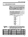
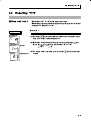
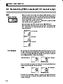
3.2
J
BASIC OPERATION
Setting the Input Type
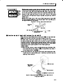
The E5EN supports four input types: platinum resistance thermometer,
thermocouple, nonĆcontact temperature sensor and analog inputs. Set the
input type matched to the sensor used in the input type" parameter. The
E5EN specifications support two types of inputs, platinum resistance
thermometer input types and thermocouple input type, whose set values
differ. Check the type of E5EN at purchase.
Input type
_
Setting the input type thermocouple KĆ20.0 to 500.0 C".
Operation Procedure
(1) Press the
key for at least three seconds to move from the operaĆ
tion level" to the initial setting level".
Operation level
Initial setting level
key to enter the set value of the desired sensor. When
(2) Press the
using K thermocouple (Ć20.0 to 500.0 C), enter 1" as the set value.
Hint: The set value is fixed if you do not operate the keys on the front panel
for two seconds after changing the parameter, or by pressing the
or
keys.
List of Input Types
_
Input type
Input type
Platinum resistance
Platinum
thermometerinput
h
i
resistance
i
type
thermometer
Name
Pt100
JPt100
Input type
Thermocouple
p
input
p
Thermocouple
p
Name
K
t
type
J
T
Set
Value
Ć199.9 to 500.0 ( C) / Ć199.9 to 900.0 ( F)
2
0.0 to 100.0 ( C)
3
Ć199.9 to 500.0 ( C) / Ć199.9 to 900.0 ( F)
4
0.0 to 100.0 ( C)
Set
Value
Analog input
_
_
_
_
/ 0.0 to 210.0 ( F)
_
_
/ 0.0 to 210.0 ( F)
Input Temperature Setup Range
_
_
_
_
_
_
Ć200 to 1300 ( C)
/ Ć300 to 2300 ( F)
1
Ć20.0 to 500.0 ( C)
/ 0.0 to 900.0 ( F)
2
Ć100 to 850 ( C)
/ Ć100 to 1500 ( F)
3
Ć20 to 400.0 ( C)
/ 0.0 to 750.0 ( F)
4
Ć200 to 400 ( C)
/ Ć300 to 700 ( F)
_
_
_
_
_
_
Ć199.9 to 400.0 ( C) / Ć199.9 to 700.0 ( F)
_
_
0 to 600 ( C)
/ 0 to 1100 ( F)
L
6
Ć100 to 850 ( C)
/ Ć100 to 1500 ( F)
U
7
Ć200 to 400 ( C)
/ Ć300 to 700 ( F)
_
_
_
_
_
_
Ć199.9 to 400.0 ( C) / Ć199.9 to 700.0 ( F)
_
_
8
Ć200 to 1300 ( C)
/ Ć300 to 2300 ( F)
R
9
0 to 1700 ( C)
/ 0 to 3000 ( F)
S
10
0 to 1700 ( C)
/ 0 to 3000 ( F)
_
_
_
_
_
_
11
100 to 1800 ( C)
/ 300 to 3200 ( F)
10 to 70 C
12
0 to 90 ( C)
/ 0 to 190 ( F)
_
_
_
_
_
_
_
_
_
_
_
_
60 to 120 C
13
0 to 120 ( C)
/ 0 to 240 ( F)
115 to 165 C
14
0 to 165 ( C)
/ 0 to 320 ( F)
160 to 260 C
15
0 to 260 ( C)
/ 0 to 500 ( F)
0 to 50mV
16
For scaling use ranges from Ć1999 to 9999
or Ć199.9 to 999.9.
Shaded ranges indicate default settings.
3-4
/ Ć300 to 1500 ( F)
5
B
ES1A
_
_
0
18
sensor
_
Ć200 to 850 ( C)
1
E
N
t
temperature
t
_
0
17
NonĆcontact
Input Temperature Setup Range
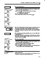
3.3 Selecting _C/_F
3.3
J
_ _
Selecting
_FF
Selecting _C/
C/
Temperature unit
Operation Procedure
Operation level
Initial setting level
• ! ! %_
%_ ! !!" "!
• ! ! !!" "! ! %!!" "! ! %!
!! # "! % _
! %_
!
$ ! ! ! ! # ! %'
! # ! ! %! !! #
Input type
Temperatureunit
! ! %!!" "! ! $ !
!
$ ! ! ! %_
%_
_
_
!" ! ! %! # !
$
$ ! ! 3-5
CHAPTER 3 BASIC OPERATION
3.4
Selecting PID Control or ON/OFF Control
The E5EN supports two control methods, 2ĆPID control and ON/OFF
control. The control method is selected by the PID / ON/OFF" parameter
in the initial setting level". When this parameter is set to
", 2ĆPID
control is set, and when set to
", ON/OFF control is set (default).
F 2ĆPID control
PID control is set by AT (autoĆtuning), ST (selfĆtuning) or manual setup.
For PID control, set the PID constants in the proportional band (P)",
integral time (I)" and derivative time (D)" parameters.
F ON/OFF control
In ON/OFF" control, the control output is turned ON when the process
value is lower than the current set point, and the control output is turned
OFF when the process value is higher than the current set point (reverse
operation).
3-6
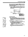
3.5 Setting Output Specifications
3.5
J
Setting Output Specifications
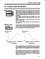
Control period
Control
period
(OUT1)
Control
period
(OUT2)
• ) ) %*)&*) &'% %$)'%" &'% %* (%')' &'% &'%+(
))' %$)'%" &'%'#$ ) ( '%##$ )% () ) %$)'%" &'%
)% (%$( %' #%' )!$ ) " -&)$. $ ) ( % '". %*)1
&*) $)% %$(')%$ $(('. ' *() ) %$)'%" &'% . )'"
%&')%$ %' -#&" ,$ ) %$)'%" &'% &'#)'( ' () )%
)' *")(
• ) ) %$)'%" &'% $ ) /%$)'%" &'% $ /%$)'%"
&'% &'#)'( $)" ())$ "+" *") ( /
(%$(
• $+' %$)'%" %*)&*) ( ) *''$) %*)&*) /%$)'%" &'%
$$%) *(
• /%$)'%" &'% &'#)' $ *( %$". $ )$ $
%%"$ %$)'%"
J
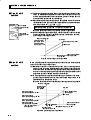
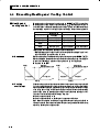
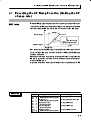
Direct/reverse
operation
• /') %&')%$ ''( )% %$)'%" ,' ) #$&*") +'" (
$'( %'$ )% ) $'( $ ) &'%(( +"* ")'$)+".
/+'( %&')%$ ''( )% %$)'%" ,' ) #$&*") +'" (
'( %'$ )% ) $'( $ ) &'%(( +"*
Manipulated variable
100%
Manipulated variable
100%
0%
Low temperature Set value
Direct operation
High temperature
0%
Low temperature Set value High temperature
Reverse operation
%' -#&" ,$ ) &'%(( +"* )#&')*' ( "%,' )$
) () &%$) )#&')*' $ )$ %$)'%" (.()# ) #$&1
*") +'" $'(( . ) '$ ),$ ) $ +"1
*(
%'$". )( %#( /'+'( %&')%$ $ )$ %$)'%" (.(1
)# %' ")'$)+". /') %&')%$ $ %%"$ %$)'%" (.()#
• ')'+'( %&')%$ ( () $ ) /')'+'( %&')%$ &'#1
)' $)" ())$ "+" /')'+'( %&')%$ &'#)'
*") ( /'+'( %&')%$
3-7
CHAPTER 3
BASIC OPERATION
Operation Procedure
In this example, monitor the input type", temperature unit", direct/reĆ
verse operation" and control period (OUT1)" parameters.
input type" = ": K thermocouple
temperature unit" = ": _C
direct/reverse operation" =
": reverse operation
control period (OUT1)" = 20 (secs)"
(1) Press the
key for at least three seconds to move from the operaĆ
tion level" to the initial setting level".
Operation level
Initial setting level
Input type
Temperature unit
Control period
(OUT1)
Direct/reverse
operation
Operation level
PV/SP
3-8
(2) The input type is displayed. When you are setting the input type for
the first time, ": K thermocouple is set. (0" is set in the case of a
platinum resistance thermometer.) To select a different sensor, press
the
or
keys.
(3) Select the temperature unit" parameter by pressing the
Default is ": _C. To select ": _F, press the
key.
key.
(4) Select the control period (OUT1) parameter by pressing the
Default is 20".
key.
(5) Select the direct/reverse operation" parameter by pressing the
key. Default is
": reverse operation. To select
": direct
operation, press the
key.
(6) To return to the operation level" press the
second.
key for at least one
3.6 Setting the SP
3.6
Setting the SP
Operation level
J
Changing the SP
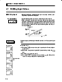
%" 6,-".0&,+ )"2") &/ !&/-)5"! 3%"+ 0%" &/ 01.+"! %"
1--". !&/-)5 ,
!&/-)5 !&/-)5/ 0%" -., "// 2)1" +! 0%" ),3". !&/8
-)5 , !&/-)5 !&/-)5/ 0%" /"0 -,&+0
• %" /"0 -,&+0 ++,0 " %+$"! 3%"+ 0%" 6,-".0&,+!'1/0*"+0
-.,0" 0&,+ -.*"0". &/ /"0 0, 6 ,. !"0&)/ /"" 6 /&+$ 0%" "5
.,0" 0 "2")/
• , %+$" 0%" /"0 -,&+0 -."// 0%"
,.
("5/ &+ 0%" 6
-.*"0". ,-".0&,+ )"2") +! /"0 0%" !"/&."! /"0 2)1" %" +"3 /"0
-,&+0 &/ /")" 0"! 03, /" ,+!/ #0". 5,1 %2" /-" &#&"! 0%" +"3 2)1"
• 1)0& &/ 1/"! 0, /3&0 % "03""+ 03, ,. #,1. /"0 -,&+0/
"" 6 , /" 2"+0 +-10 #,. !"0&)/
Operation Procedure
Operation level
+ 0%&/ "4*-)" %+$" 0%" /"0 -,&+0 #.,* 6_ 0, 6_
,.*))5 0%" 6 -.*"0". &/ !&/-)5"! %" /"0 -,&+0 &/ 6_
/" 0%"
("5/ 0, /"0 0%" /"0 -,&+0 0, 6_
3-9
CHAPTER 3
3.7
J
BASIC OPERATION
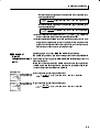
Executing ON/OFF Control
# . $#)'$! ) $#)'$! $*)%*) )*'#( ,# ) *''#)!$#)'$!! )"%')*' '( %'() () %$#) # ) "#%*!)
+'! )*'#( ) )"%')*' #( )$ !! # ) $#)'$! )*'#(
# ( $%')$# ( '%) ) ')# %$#) ) )( )" $,
"* ) )"%')*' "*() !! $' $#)'$! )*'#( # ( )'0
"# - ) .-()'(( %'")' !($ $, "* ) "#%0
*!) +'! "*() *() # '(%$#( # ) #'( $' '( #
) %'$(( +!* ( )'"# - .')'+'( $%')$# %'")'
ON/OFF Control
F
Hysteresis
• ,)# ),# 0 $#)'$! # $#)'$! ( '' $*) ) . %'")' #)! ())# !+! # )( %'"0
)' ( () )$ .
0 $#)'$! ( (!) # ,# () )$ .
$#)'$! ( (!) *!) ( .
• # $#)'$! ) -()'(( ( *( ( '#)! $' (,)#
) $*)%*) ,# ) )"%')*' "$+( ,- '$" ) '&*' ()
%$#) # ( *( + ()!)- '$*# ) () %$#)
$#)'$! $*)%*) # $#)'$! $*)%*) *#)$#( ' ()
# ) -()'(( # -()'(( *#)$#( '(%)+!-
• # ()#' $#)'$! )# $' $$!# $#)'$! ) .-()'((
())# ( *( ( ) -()'(( ())# # ) *()"#) !+!
''!(( $ ) $#)'$! )-% )# $#)'$! $' $$!# $#)'$!
Hysteresis (OUT1)
ON
OFF
F
PV
Set point
3Ćposition
control
• # )# # $$!# $#)'$! # # ' ,' $) $#)'$!
$*)%*)( ' . # () )$ )' ) )# $' $$!# ( $
0%$()$# $#)'$! ( " %$((!
Revers operation
Dead band
Hysteresis (OUT2)
Hysteresis (OUT1)
ON
Heating
Cooling
side
side
OFF
PV
Set point
3-10
3.7 Executing ON/OFF Control
Parameters
Symbol
Parameter Name: Level
Standard/heating and cooling:
Description
For specifying control method
Initial setting level
PID / ON/OFF:
For specifying control method
Initial setting level
Direct/reverse operation:
For specifying control method
Initial setting level
Dead band:
Heating and cooling control
Adjustment level
Cooling coefficient:
Heating and cooling control
Adjustment level
Hysteresis (OUT1):
ON/OFF control
Adjustment level
Hysteresis (OUT2):
ON/OFF control
Adjustment level
J
•
To execute ON/OFF control, set the set point," PID / ON/OFF" and
hysteresis" parameters.
Setup
Setting the PID / ON/OFF parameter
Operation Procedure
Operation level
PV
In this example, check first that the PID / ON/OFF" parameter is set to
" in the initial setting level".
(1) Press the
key for at least three seconds to move from the operaĆ
tion level" to the initial setting level".
(2) Display the input type" parameter in the initial setting level.
(3) Select the PID / ON/OFF" parameter by pressing the
Initial setting level
Input type
(4) Check that the set value is
key.
" (default).
PID / ON/OFF
Set the following set point value.
•
Setting the SP
Operation Procedure
In this example, set the set point value (200). The lower display (No.2 disĆ
play) shows the set value (SP value).
(1) Select PV/SP" at the operation level.
Operation level
PV/SP
(2) Use the
keys to set the SP value. (For example, 200) To set the
value either press the
key or wait more than two seconds.
3-11
CHAPTER 3 BASIC OPERATION
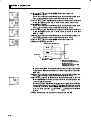
3.8
J
Determining PID Constants (AT, ST, manual setup)
AT.
(autoĆtuning)
• # -$) ,)( )($0()## ( $%(")" $#'(#(' $& ( '(
%$#( )&# %&$&" ,)($# & )($"(!!- '( - $&!- #0
# ( "#%)!( *&! ($ !)!( ( &(&'(' !! (
.!"( -! "($ $ ( $#(&$! (&(
• $ ,)( )($0()## '%- . ,)( # ($ #! )($0()## '%- .
#!
• )($0()## ##$( ,)( )&# $#(&$!
• &')!( $ )($0()## ' "&&$& # ( .%&$%$&($#! #
.#(&! (" # .&*(* (" %&"(&' # (
.)'("#( !*!
Adjustment level
Proportionalband
Integratedtime
Derivative time
F
Description
)($0()## ' '(&( +# ( . ,)(#! %&"(& ' '(
($ . )&# ,)($# $ ( $ '%!- $& ( . ,)(#0
! %&"(& !# ' # #' ( . ,)(#! %&"(&
()&#' # ( $ '%!- '($%' !# #
,)(#!
$ '%!-
During AT execution
-$) "$* ($ ( .$%&($# !*! )&# ,)($# ( $ '%!!# ' ($ #( (( ' # ,)(
$ '%!-
During AT execution
#!- ( .$"")#($#' +&(# .&)#'($% # . ,)($##0
! %&"(&' # # )&# ,)($# (& %&"(&'
##$( #
3-12
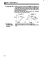
3.8 Determining PID Constants (AT, ST, manual setup)
Operation Procedure
Adjustment Level
AT execute/
cancel
Execute autoĆtuning (AT).
(1) Press the
key for less than one second to move from the operaĆ
tion level" to the adjustment level".
(2) Press the
key to start execution of AT (autoĆtuning).
" is displayed during AT execution.
(3)
" is displayed when AT ends.
(4) To return to the operation level," press the
key.
Operation level
PV
J
ST (selfĆtuning)
Operation Procedure
The ST (selfĆtuning) function executes tuning from the start of program
execution to calculate PID constants matched to the control target.
Once the PID constants have been calculated, ST is not executed when the
next control operation is started as long as the set point remains
unchanged.
ST (selfĆtuning) is executed when the ST" parameter is set to ON" in the
initial setting level".
When the ST function is in operation, be sure to turn the power supply of
the load connected to the control output ON simultaneously with or before
starting operation of the E5EN.
Execute selfĆtuning (ST).
Initial setting level
Input type
(1) Press the
key for at least three seconds to move from the operaĆ
tion level" to the initial setting level".
ST
(2) Select the ST" parameter by pressing the
(3) Press the
ST
About PID parameĆ
ters
key to select
key.
" (default).
(4) To return to the operation level," press the
key. The temperature
display blinks during selfĆtuning (ST) execution.
When control characteristics are already known, the PID parameters can be set
directly to adjust control.
PID parameters are set in the proportional band" (P), integrated time" (I) and
derivative time" (D) parameters in the adjustment level".
3-13
CHAPTER 3 BASIC OPERATION
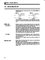
J
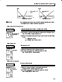
ST start
conditions
SelfĆtuning by step response tuning (SRT) is started when the following
conditions are met after program execution is started and the set point is
changed.
At Start of Program Execution
1. Theset point at the start of program execuĆ
tion differs from the set point (See Note 1)
when the previous SRT was executed.
2. The difference between the temperature at
start of program execution is larger than
(current proportional band 1.27+4_C) or
the (ST stable range) whichever is larger.
3. The temperature at the start of program
executionis smaller than the set point
duringreverse operation, and is larger than
the set point during direct operation.
4. No reset from input error
When Set Point Is Changed
1. The new set point differs from the set point
(See Note 1) used when the previous SRT
was executed.
2. The set point change width is larger than(curĆ
rentproportionalband 1.27+4_C)orthe(ST
stable range) whichever is larger.
3. Duringreverse operation, the new set point
is larger than the set point before the
change; and during direct operation, the
new set point is smaller than the set point
beforethe change.
4. The temperature is in a stable state (See
Note2). (An equilibrium state is acceptable
when the output is 0% when the power is
turned ON.)
Note:
(1) The previous SRT-implemented set point is called the set point obĆ
tained by calculating the PID constant by the previous SRT.
(2) In this state, the measurement point is within the ST stable range.
(3) In this state, the change width of the PV every 60 seconds is at the
ST stable range or less.
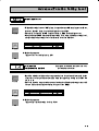
PID constants are not modified for the currently preset set point by selftuning (ST) in the following instances:
(1) When the PID constants have been changed manually with ST set
to ON.
(2) When auto-tuning (AT) has been executed.
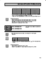
J
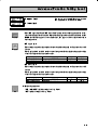
ST stable range
The ST stable range is a condition for determining the conditions under
which ST (selfĆtuning) functions.
In this example, let's set the ST stable range to 20_C.
Operation Procedure
Advanced function setting level
ST stable range
3-14
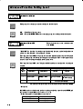
(1) Select the ST stable range" parameter by pressing the
advanced function setting level".
(2) Set to 20_C (deviation) using the
keys.
key in the
3.8 Determining PID Constants (AT, ST, manual setup)
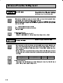
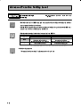
J Manual setup
Operation Procedure
The individual PID constants can be manually set in the Proportional
band", integral time", and Derivative time" parameters in the adjustĆ
ment level".
In this example, set the proportional band" parameter to 10.0", the
integrated time" parameter to 250" and the derivative time" parameĆ
ter to 45".
(1) Press the
key to move from the operation level" to the adjustĆ
ment level".
Adjustment level
AT execute/
cancel
(2) Select proportional band" by pressing the
(3) Use the
keys to set the parameter to 10.0".
(4) Select integrated time" by pressing the
Proportional
band
(5) Use the
key.
keys to set the parameter to 250".
(6) Select derivative time" by pressing the
(7) Use the
key.
key.
keys to set the parameter to 45".
(8) To return to the operation level," press the
key.
Integrated time
Derivative time
Proportional
Operation
When PID constants I (integral time) and D (derivative time) are set to 0", control
is executed according to proportional operation. The default set point becomes the
center value of the proportional band.
Related parameter
manual reset value" (adjustment level)
3-15
•
!' )+()(+-"('% ' ", #.,-
!' ",
-
! .+/ +",,
%.
,-% -"& ", !"/ )+/'-"'
"'+,
!' ",
(/+,!((-
%.
/+,!((- ' !.'-"'
(.+ !(04
/+ -! ,- )("'- ", *."$%1 +!
-+ 0!"! -! .+/ ,-"%"2,
+,
•
+.%%1 ' %('
!' "'- +% -"& ", #.,-
!' ",
"'+,
- -$, %('
-"& (+ -! )+(,,
-
/%. -( +! -! ,- )("'- - -$,
%.
-"& -( !"/ ,-% ,-- !(04
/+ -!+ ", %"--% (/+,!((-.'+4
,!((- ' !.'-"' !' ",
-
/+,!((-.'+,!((-
+,
%.
(.+ ' -! .+/ +",, *."$%1
•
'
!.'-"'
!' +"/-"/ -"& ", #.,-
!' ",
"'+,
%.
/+,!((-.'+,!((-
'
,-%
-"& + +. !(0/+ "' !.'-4
"'
(.+, (' !' , "' -! .+/
"-,%
!' ",
-
/+,!((-.'+,!((- "'+, '
+,
%.
"- -$, -"& (+ -! )+(,, /%. -(
+! -! ,- )("'-
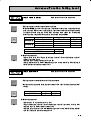
3.9 Alarm Outputs
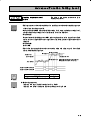
3.9
J
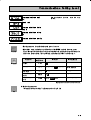
Alarm Outputs
• $ !'&"'& ! &! % $ &$ + & ! &! ! ,$
&+" ,$ +%&$%%
• !!) %$% & ,$ &+" ,$ (' ,'""$.&
$ ,!)$.& $ "$&$%
Alarm type
Alarm Output Operation
Set
Alarm Type
Value
When alarm value
When alarm value
X is positive
X is negative
0
Alarm function OFF
Output OFF
1
UpperĆ and lowerĆlimit
(deviation)
ON
UpperĆlimit(deviation)
ON
L
OFF
3
4
1
5
1
6
7
8
9
10
11
X
OFF
UpperĆ and lowerĆlimit alarm
with standby sequence
ON
H
(deviation)
UpperĆlimit alarm with standby
sequence (deviation)
ON
ON
OFF
OFF
X
ON
X
ON
ON
X
ON
ON
SP
X
0
X
0
X
OFF
0
X
ON
OFF
X
OFF
0
OFF
SP
OFF
0
OFF
X
ON
SP
OFF
AbsoluteĆvalue lowerĆlimit with
standby sequence
4
SP
ON
AbsoluteĆvalueupperĆlimit with
standby sequence
H
X
OFF
AbsoluteĆvaluelowerĆlimit
SP
3
X
ON
AbsoluteĆvalueupperĆlimit
X
SP
OFF
LowerĆlimit alarm with standby
sequence(deviation)
SP
SP
L
OFF
OFF
SP
OFF
X
ON
L
ON
OFF
X
OFF
UpperĆ and lowerĆlimit range
(deviation)
ON
SP
ON
LowerĆlimit(deviation)
2
SP
1
2
H
ON
OFF
0
0
X
0
'""$. !)$.& ('% *"$%% % , , %& " &+ !$ $
"! & )& %& ('% & (' ""$. !)$.& $
Case 1
Case 2
Case 3 (Normally ON)
H < 0, L < 0
L
H SP
SP L
L
H
H < 0, L > 0
H > 0, L < 0
|H| < |L|
|H| > |L|
SP
H
y
x
H < 0, L > 0
H
L SP
|H|
|L|
H > 0, L < 0
SP H
L
& (' ""$. !)$.& $ Case 1
Case 2
|H|
|L|
Case 3 (Normally OFF)
H < 0, L < 0
L
H SP
SP L
L
H
H < 0, L > 0
H > 0, L < 0
|H| < |L|
|H| > |L|
SP
H
y
x
H < 0, L > 0
H
|H|
L SP
|L|
H > 0, L < 0
SP H
L
|H|
|L|
& (' ""$. !)$.& $ )& %& + %#' !$ & !( '""$. !)$.& $
. %% & $ % !$+ '""$. !)$.& ('% ! +%&$%% !($"
Cases 1 and 2 example:
. % & $ % !$+ & (' ""$. !)$.& $ )& %& + %#' $ % !$+ '""$. !)$.& ('% ! +%&$%% !($"
3-17
CHAPTER 3 BASIC OPERATION
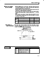
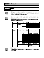
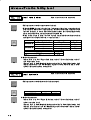
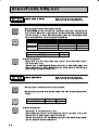
J Alarm value
• $)% +0(* ) *+ "&(&&+$0 ') ! 1$)% +0( +' "&"+"$
*++"& $-$ ! ,$+ -$, "* 1 (()3$"%"+ $)%
• $)% -$,* ) "&"+ 0 1 "& +! +$ '& +! ()-"',* ( LowerĆlimit !& +! ,(() & $'.) $"%"+* ) *+ "&(&&+$0 1 "* "*($0
alarm value ') ,(() $"%"+ -$,* & 1 "* "*($0 ') $'.) $"%"+ -$,*
• ' *+ +! ,(()3 & $'.)3$"%"+ $)% -$,* ') -"+"'& *+ +!
,(() & $'.) $"%"+* "& ! ' +! 1$)% ,(() $"%"+ +' &
1$)% $'.) $"%"+ +' ()%+)* '()+"'& $-$
UpperĆlimit
alarm value
Alarm value
Operation Procedure
Initial setting level
+ 1$)% +' +! ,(()3$"%"+ $)% ! '$$'."& *!'.* )$+
()%+)* & *+,(* & +!"* /%($ +! $)% ',+(,+ "* +"- .!&
+! *+ ('"&+ "* / 0 1_ ! +%()+,) ,&"+ "& +!"* /%($
"* 1_
1$)% +0(
1 ,(()3$"%"+ $)% -"+"'&
1$)% -$, 1
Input type
)** +!
#0 ') + $*+ +!) *'&* +' %'- )'% +! 1'()3
+"'& $-$ +' +! 1"&"+"$ *++"& $-$
Alarm 1 type
Operation level
$+ +! 1$)% +0( ()%+) 0 ()**"& +!
#0 !#
+!+ +! 1$)% +0( ()%+) "* *+ +' 1 ,$+ ,(()3$"%"+
$)%
' )+,)& +' +! 1'()+"'& $-$ ()** +!
*'&
PV/SP
$+ 1$)% -$, 0 ()**"&
* +!
Alarm value 1
3-18
#0 ') + $*+ '&
#0* +' *+ +! ()%+) +' 1
3.10 Heater Burnout Alarm (HBA)
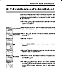
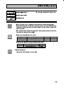
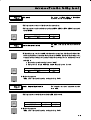
3.10 Heater Burnout Alarm (HBA)
J
HBA detection
To CT terminal
Heater lead
J
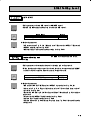
Operating
conditions
• !/!- 0-*+0/ !/!/%+* 2+-'. . "+((+2.
+**!/ /$! 0--!*/ /-*."+-)!- /+ /!-)%*( +. * * %*.!-/ /$! $!/!- (! /$-+0#$ /$! $+(! +- .,!%"%/%+*.
)+ !(. * !3/!-*( %)!*.%+*. +" 0--!*/ /-*."+-)!-. /$/ *
! 0.! +* /$%. +*/-+((!- .!! 5,,!* %3 +0/ 0--!*/ -*.7
"+-)!- $!* 0--!*/ "(+2. /$-+0#$ /$%. (! /$! 0--!*/ /-*."+-)!#!*!-/!. 0--!*/ ,-+,+-/%+*( /+ /$! 0--!*/ 1(0! $! )!.0-!. /$%. 0--!*/ /+ (0(/! /$! 0--!*/ "(+2%*# /+ /$!
$!/!-
" /$! $!/!- %. 0-*! +0/ /$! 0--!*/ )!.0-! / /$! 0--!*/
/-*."+-)!- !-!.!. $%. 1(0! %. +),-! 2%/$ /$! 1(0! .!/ .
/$! 5$!/!- 0-*+0/ .!/ 1(0! * /$! +0/,0/ !+)!. /%1! .
/$! $!/!- 0-*+0/ (-)
• !/ /$! $!/!- 0-*+0/ .!/ 1(0! %* /$! 5$!/!- 0-*+0/ !/!/%+*
,-)!/!- &0./)!*/ (!1!( + )+*%/+- /$! 0--!*/ 1(0! +" /$! 0-7
-!*/ /-*."+-)!- 0.! /$! 5$!/!- 0--!*/ )+*%/+- ,-)!/!-
• $!* "0*/%+* %. *+/ 0.! .!/ /$! 5$!/!- 0-*+0/ ,-)!/! 1*! "0*/%+* .!//%*# (!1!( /+ 5
VV VV
• $! "0*/%+* * ! 0.! 2$!* /$! +,/%+* 0*%/ 7
%.
)+0*/! +* /$! ! .0-! /+ +**!/ /$! /+ /$! * ,..
/$! $!/!- (! /$-+0#$ /$! $+(!
• 0-* /$! $!/!- / /$! .)! /%)! . +- !"+-! /0-*%*# /$! " /$! $!/!- %. /0-*! "/!- /0-*%*# /$! /$! $!/!- 0-*7
+0/ (-) 2%(( /%1/!
• +*/-+( %. +*/%*0! !1!* %" /$! $!/!- 0-*+0/ (-) %. /%1! $/ %.
/$! //!),/. /+ +*/-+( /$! $!/!- +* 2$%$ /$! $!/!- 0-*+0/
(-) $. *+/ +0--! • $! $!/!- 0-*+0/ (-) %. !/!/! 2$!* /$! +*/-+( +0/,0/ %. +*/%*7
0+0.(4 "+- ). +- )+-!
• $! -/! 0--!*/ 1(0! )4 .+)!/%)!. %""!- .(%#$/(4 "-+) /$! /0(
0--!*/ "(+2%*# /+ /$! $!/!- $!' /$! 0--!*/ 1(0! %* * /0( +,!-7
/%*# .//! %* /$! 5$!/!- 0--!*/ )+*%/+- ,-)!/!-
• " /$!-! %. (%//(! %""!-!*! !/2!!* /$! 0--!*/ %* *+-)( .//! * /$!
0--!*/ %* /$! 0-*+0/ .//! !/!/%+* )4 !+)! 0*./(! * $!/!- +" 0--!*/ +- (!.. )%*/%* %""!-!*! +" +- )+-!
* $!/!- +" 0--!*/ +- )+-! )%*/%* %""!-!*! +" +)+-!
• $! "0*/%+* **+/ ! 0.! 2$!* /$! $!/!- %. +*/-+((! 4 ,$.! +*/-+( .4./!) +- 4(! +*/-+( .4./!) (.+ 7,$.! $!/!-. *7
*+/ ! 0.! $!* $!/!- 0-*+0/ %. !/!/! +* 7,$.! $!/!- 0.! /$! 7
2%/$ #/! %*,0/ /!-)%*( !! /$! -!.,!/%1! / .$!!/ "+- !/%(.
jj7j
3-19
CHAPTER 3 BASIC OPERATION
J Setup
To activate the heater burnout alarm, set the HBA used" parameter
(advanced function setting level) to ON" and the heater burnout set value
in the heater burnout detection" parameter (adjustment level).
Operation Procedure
In this example, set the heater burnout detection" parameter to 2.5".
• Moving to the advanced function setting level
Operation level
PV/SP
Initial setting level
The default of the heater burnout" parameter is already ON", so set the
heater burnout detection" parameter.
(1) Move to the advanced function setting level.
key for at least three seconds to move from the operaĆ
Press the
tion level" to the initial setting level".
Input type
(2) Then move to advanced function setting level" by pressing the
key.
(3) Use the
the initial setting level" to the advanced function setting level".
The top parameter in the advanced function setting level" is disĆ
played.
Move to advanced
function setting level
Advanced function setting level
keys to input the password (-169"), and move from
key.
(4) Select the HBA used" parameter by pressing the
Make sure that this parameter is set to ON" (default).
Next, set the heater current value monitor" parameter.
HBA used
• Setting heater burnout detection
Operation level
PV/SP
Adjustment level
AT execute/cancel
(5) Press the
key for at least one second to move from the advanced
function setting level" to the initial setting level" and then to the
operation level".
(6) Press the
key for less than one second to move from the operaĆ
tion level" to the adjustment level".
(7) Select the heater current value monitor" parameter by pressing the
key. Check the current value. Next, set the heater burnout detecĆ
tion" parameter.
Heater current value
(8) Select the heater burnout detection" parameter by pressing the
monitor
Heater burnout detection
key.
Set the current value as a reference value. Set this set value so that
there is a large difference between the current flowing to the heater
lead when heater operation is normal and the current flowing when
a heater burnout occurs.
(9) For example, set 2.5". To return to the operation level", press the
key for less than one second.
3-20
3.10 Heater Burnout Alarm (HBA)
J
How to calculate
• ( 1(0" 0%" /"0 2(1" 5 0%" #+((+3&*$ "-10&+*
detection current
"0 2(1" values
• + /"0 0%" 2(1" +# 0%" %"0". 1.*+10 3%"* 03+ +. )+." %"0"./ ." +*8
*" 0"! 0%.+1$% 0%" 1/" 0%" 1."*0 2(1" +# 0%" /)(("/0 %"0". +*8
*" 0"! 0%" 1.."*0 2(1" 3%"* +*" +# 0%" %"0"./ 1.*/ +10 &# (( 0%"
%"0"./ %2" 0%" /)" 1.."*0 2(1"
• '" /1." 0%0 0%" #+((+3&*$ +*!&0&+*/ ." /0&/#&"!
"0". +# 1.."*0 +. ("//
1.."*0 2(1" 0 *+.)( +,".0&+* 8
1.."*0 2(1" 0 %"0". 1.*+10
%"* 0%" ."/1(0*0 1.."*0 &/ ("// 0%* !"0" 0&+* &/ 1*/0("
"0". +# 1.."*0 +. )+."
1.."*0 2(1" 0 *+.)( +,".0&+* 8
1.."*0 2(1" 0 %"0". 1.*+10 %"* 0%" ."/1(0*0 1.."*0 &/ ("// 0%* !"0" 0&+* &/ 1*/0("
• %" /"00&*$ .*$" &/ 0+ "0". 1.*+10 &/ *+0 !"0" 0"! 3%"*
0%" /"0 2(1" &/ 6 +. 6 %"* 0%" /"0 2(1" &/ 6 0%" %"0".
1.*+10 (.) &/ /"0 0+ 6 *! &# 0%" /"0 2(1" &/ 6 0%" %"0".
1.*+10 (.) &/ /"0 0+ 6
• "0 0%" 0+0( 1.."*0 2(1" 0 *+.)( %"0". +,".0&+* 0+ +. ("//
%"* /"0 0+ 6 6
&/ !&/,(5"! &* 0%" 6%"0". 1.."*0 )+*&8
0+. ,.)"0".
1.."*02(1" 0 *+.)( +,".0&+* 1.."*0 2(1" 0 %"0". 1.*+10
y
y
J
4),(" %"* 1/&*$ ' %"0".
Example
Control output
Heater
1.."*0 !1.&*$ *+.)( +,".0&+* 1KW
AC200V
CT
E5EN
14
+ t 1.."*0 0 %"0". 1.*+10 "0 2(1" 1.."*0 0 *+.)( +,".0&+* 8 1.."*0 0 %"0".
8 1.*+10 ) +
+
+
y
15
4),(" %"* 1/&*$ 0%."" ' %"0"./
Control output
Heater
1KWx3
AC200V
CT
E5EN
Parameters
14
+
y
1.."*0 0 1.*+10 +# +*" %"0". "0 2(1" 1.."*0 0 *+.)( +,".0&+* 8 1.."*0 0 %"0".
1.*+10 8 1.."*0 0 *+.)( +,".0&+* ) +
+
+
+
y
15
Symbol
Parameter : Level
Description
Heater current value monitor:
Adjustment level
For heater current value monitor
Heater burnout detection:
Adjustment level
For HBA detection
Heater burnout hysteresis:
Advanced function setting level
For HBA detection
Heater burnout latch:
Advanced function setting level
For HBA detection
3-21
CHAPTER 3 BASIC OPERATION
3.11 Requests during Operation
1)
About four seconds is required for outputs to turn ON when the power
is turned ON. Take this into consideration when the temperature conĆ
troller is incorporated into a sequence circuit.
2)
Allow at least 30 minutes for warming up.
3)
When self-tuning is used, turn the temperature controller and load
(e.g. heater) ON simultaneously or turn the load ON before the temĆ
perature controller. If the load is turned ON before the temperature
controller, correct self-tuning and optimum control are no longer
possible.
When operation is started after warm-up, turn the power OFF once
after warm-up is completed, and then turn the temperature controlĆ
ler and load ON simultaneously. (Instead of turning the temperature
controller power ON again, moving from the STOP to the RUN mode
also is possible.)
4)
The temperature controller may be subject to the influence of radio
interference if used near a radio, TV or wireless equipment.
3-22
CHAPTER 4 APPLIED OPERATION
4
CHAPTER 4
APPLIED OPERATION
4.1
Shifting Input Values . . . . . . . . . . . . . . . . . . .
4Ć2
Shifting input
4Ć2
.........................
How to calculate input shift values
(2Ćpoint shift) . . . . . . . . . . . . . . . . . . . . . . . . . .
4Ć3
1Ćpoint shift method . . . . . . . . . . . . . . . . . . . .
4Ć4
2Ćpoint shift method . . . . . . . . . . . . . . . . . . . .
4Ć4
Example of 2Ćpoint temperature
4.2
4.3
4.4
4.5
4.6
4.7
4.8
4.9
input shift . . . . . . . . . . . . . . . . . . . . . . . . . . . . .
4Ć5
Alarm Hysteresis
......................
4Ć6
Standby sequence . . . . . . . . . . . . . . . . . . . . . .
4Ć6
Alarm latch . . . . . . . . . . . . . . . . . . . . . . . . . . . .
4Ć6
Close in alarm/open in alarm . . . . . . . . . . . .
4Ć7
Setting Scaling Upper and Lower Limits
(analog input) . . . . . . . . . . . . . . . . . . . . . . . . .
4Ć8
Analog input . . . . . . . . . . . . . . . . . . . . . . . . . .
4Ć8
Executing Heating and Cooling Control . .
4Ć10
Heating and cooling control . . . . . . . . . . . . .
4Ć10
Setup . . . . . . . . . . . . . . . . . . . . . . . . . . . . . . . . .
4Ć11
To Use Event Input . . . . . . . . . . . . . . . . . . . .
4Ć12
Setting event input . . . . . . . . . . . . . . . . . . . . .
4Ć12
How to use multiĆSP . . . . . . . . . . . . . . . . . . .
4Ć12
Setting by key operation . . . . . . . . . . . . . . . .
4Ć13
Setup . . . . . . . . . . . . . . . . . . . . . . . . . . . . . . . . .
4Ć13
Executing run/stop control . . . . . . . . . . . . . .
4Ć14
Setting the SP Upper and
Lower Limit Values . . . . . . . . . . . . . . . . . . . . .
4Ć15
Set point limitter . . . . . . . . . . . . . . . . . . . . . . .
4Ć15
Setup . . . . . . . . . . . . . . . . . . . . . . . . . . . . . . . . .
4Ć16
Executing the SP Ramp Function
(limiting the SP change rate) . . . . . . . . . . . .
4Ć17
SP ramp . . . . . . . . . . . . . . . . . . . . . . . . . . . . . .
4Ć17
To Move to the Advanced Function
Setting Level . . . . . . . . . . . . . . . . . . . . . . . . . .
4Ć19
Using the Key Protect Level . . . . . . . . . . . . .
4Ć20
Key protect . . . . . . . . . . . . . . . . . . . . . . . . . . . .
4Ć20
4-1
CHAPTER 4 APPLIED OPERATION
4.1
J
Shifting Input Values
Shifting input
• #%)( '( (-% "( ($ ( '#'$& )&&#(!- '!( # (
.#%)( (-% %&"(& ' '%!-
F
• 0%$#( '( ' %%! $#!- $& #$#0$#(( ("%&()& '#'$&'
1Ćpoint shift
• ( 0%$#( '( $#!- ( *!) '( ($ ( ."%&()& #%)( '(
%&"(& )'("#( !*! ' %%! ($ ( #(& ("%&()& #%)(
&# $& ,"%! ( #%)( '( *!) ' '( ($ ._ ( %&$''
*!) ' (&( ' ._ (& #%)( '( ' %%! +# ( %&$0
'' *!) ' _
Temperature
UpperĆlimit
value
LowerĆlimit
value
0
Operation Procedure
After shift
Before
shift
Input shift value
Input
100
# (' ,"%! '( ( #%)( $ ( '#'$& - ._ - 0%$#( #%)(
'(
%&($# !*!
Operation level
&'' (
"#( !*!
- ($ "$* &$" ( .$%&($# !*! ($ ( .)'(0
!( ( .("%&()& #%)( '( %&"(& - %&''# (
-
Adjustment level
' (
-' ($ '( .
$ &()&# ($ ( .$%&($# !*! %&'' (
*!) ' _ !&& (# $& '( ' %%!
Temperature input
shift
Operation level
4-2
- %&$''
4.1 Shifting Input Values
F
2Ćpoint shift
UpperĆlimit
temperature
input shift
value
LowerĆlimit
temperature
input shift
value
• "'& &"$&'$ $ ! ! .! && &"$&'$ % %!$% %& + %&& (' (' !$ & '""$ !)$ "! &%
! & % %!$ $ % % && & %& "" #'+
$!%% & $ )& %"$& ('% !$ ! & $ !$
*" & '""$.& (' % %& &! ,
_ & !)$.&
(' % %& &! ,_ & % %!$ $ % %& + ($ ! _
& "'&
• & & '""$.& (' & ,'""$.& &"$&'$ "'& %&
(' "$&$ & !)$.& (' & ,!)$.& &"$.
&'$ "'& %& (' "$&$
Temperature
UpperĆlimit temperature input shift value
UpperĆlimit
value
After shift
Before shift
LowerĆlimit value
0
Input
LowerĆlimit temperature
input shift value
J
100
How to calculate input shift values (2Ćpoint shift)
& ! .! && &"$&'$ % %!$ ! % ! & &! &
!%& ! %($ &! %($ & % ! $ !'$
!$ &% $%! !%& & $!'& (' + ."! & !$ ."! & %& %
%$ &% & % !%& !'$% % % '$$ & !$ && ! &$!$ % %!$ $$!$ !)% &! & !'&"'& " ! & ! .! &&
&"$&'$ % %!$ ."! & %& $$ !'& ! + !
! .! &&
&"$&'$ % %!$% !& %& !$ !&$ "'& &+"%
[Preparations]
& &! & &"$&'$ $ & & "'& %"&! % ! &
! .! && &"$&'$ % %!$ % %'""!$& ! + &$!.
!'" "'& &+"% ! & $"$ &$!&$ " ! %'$ & &"$&'$ ! &
! &$! &$& % %!) '$ %! && ."! & %& !$ ."! &
%& $$ !'&
(C) Control target
NonĆcontact
temperature
sensor
(B) Thermometer
(A) E5EN Temperaturecontroller
Figure 1 Configuration When Compensating a NonĆcontact
Temperature Sensor
4-3
CHAPTER 4
APPLIED OPERATION
J 1Ćpoint shift
(1) In the configuration shown in Figure 1, bring the set point to near the
value at which the temperature of the control target is to be conĆ
trolled. Assume that the control target temperature (C) and the conĆ
trol target temperature (B) are matching.
(2) Check the control target temperature (B) and the controller readout
(A). Take the following value as the input shift value, and set the same
" and
".
numerical values to
method
Adjustment level
UpperĆlimit temĆ
control target temperature (B) Ć controller readout (A)
perature input shift
value
LowerĆlimit temĆ
perature input shift
value
Figure 2 shows the effect of 1Ćpoint temperature input shift.
(3) After setting the input shift values, check controller readout (A) and
control target temperature (B). If they are almost the same, this comĆ
pletes temperature input shift.
Controller readout (A)
After shift
Temperature readout
after shift (e.g. 120_C)
Input shift value (e.g. 10_C)
Temperature readout
before shift (e.g. 110_C)
0
J 2Ćpoint shift
method
Before shift
Near set point
(e.g. 120_C)
Temperature readout of
control target (B)
Figure2 1Ćpoint Temperature Input Shift
Use 2Ćpoint input shift if you want to increase the accuracy of the readout
values across the range of the sensor.
(1) Shift the controller readout by two points, near room temperature
and near the value at which the temperature of the control target is
to be controlled. For this reason, bring the control target temperature
to near room temperature and to near the set point, and check control
target temperature (B) and controller readout (A).
(2) Using equations (1) and (2) calculate the upperĆ and lowerĆlimit temĆ
perature input shift values from the readout and temperature to be
shifted that you obtained in step 1.
Figure 3 shows the effect of shift by 2Ćpoint temperature input shift.
Controller readout (A)
Set temperature
upper limit YH
(e.g. 260_C)
After shift
UpperĆlimittemperature
input shift value
Temperature readout
after input shift X2 (e.g. 110_C)
Before shift
Temperature readout
before input shift Y2 (e.g. 105_C)
Temperature readout
before input shift Y1 (e.g. 40_C)
Temperature readout
after input shift X1 (e.g. 25_C)
LowerĆlimit temperature
input shift value
Temperature readout of
control target (B)
0 X1 room temperature
(e.g. 25_C)
Near X2 set point (e.g. 110_C)
Set temperature
lower limit YL (e.g. 0_C)
Figure3 2Ćpoint Temperature Input Shift
4-4
4.1 Shifting Input Values
• - .# !)&&)1$(" +/.$)( .) &/&. .# &)1 ,9&$'$. . '* ,9
./, $(*/. -#$!. 0&/ 9 + 9 4 9 9 9 5
) 9 +/.$)( • - .# !)&&)1$(" +/.$)( .) &/&. .# /** ,9&$'$. . '* ,9
./, $(*/. -#$!. 0&/ 9 + 9 4 9 9 9 5
) 9 +/.$)( !. , - ..$(" .# &/&. 0&/ - .) 6
( 6
# % )(9
.,)&& , , )/. ( )(.,)& .," . . '* ,./, &.#)/"# .# $(*/. -#$!. 1- ,,$ )/. . .1) *)$(.- &)- .) ,))'
. '* ,./, '$ (. . '* ,./, ( ( , .) .# - . *)$(. - & .
*)$(.- &)- .) # ( )! .# - (-), ,(" .) $'*,)0 /,3 ,)-.# !/&& ,(" )! .# - (-), ' -/, ' (. ,(" J Example of
2Ćpoint
temperature input
shift
Adjustment level
LowerĆlimittemperaĆ
ture input shift value
( .#$- 2'*& 1 /- .# .) _ -* $!$.$)(
( $( +/.$)(- ( , - . . '* ,./, &)1 , &$'$. $- _
( - . . '* ,./, /** , &$'$. $- _ # % .# . '* ,./, )!
.# )(.,)& .," .
# ( .# ,))' . '* ,./, $- _ .# , )/. )( .# )(.,)&& , $- _ ( 1# ( .# . '* ,./, ( , .# - . *)$(. $- _ .#
, )/. )( .# )(.,)&& , )' -_
)1 ,9&$'$. . '* ,./, $(*/. -#$!. 0&/
9 + 9 4 9 9 9 5
UpperĆlimittemperaĆ ** ,9&$'$. . '* ,./, $(*/. -#$!. 0&/
ture input shift value
9 + 9 4 9 9 9 5
) 9 + 9
7
) 9 + 7
4-5
CHAPTER 4 APPLIED OPERATION
4.2
Alarm Hysteresis
• /)*()!) % "(# %+*&+*) - $ "(#) ( )-!* $
)* ) %""%-)
UpperĆlimit
alarm
LowerĆlimit
alarm
Alarm hysteresis
ON
ON
OFF
OFF
Alarm value
Alarm hysteresis
Alarm value
• "(# /)*()!) !) )* !$&$$*"/ %( "(# !$ * 0"(# /)2
*()!) *% &(#*() ,$ +$*!%$ )**!$ "," +"* !)
0
J
Standby
sequence
• 0*$/ )'+$ !) +$*!%$ - ! ""%-) * "(# %+*&+*) *% *#&%((!"/ !)" - !" * !()* "(# %$!*!%$ %+() (%# (
%$ * "(# %+*&+* !) *!, %( +*+( "(# %$!*!%$)
• %( .#&" !$ )*$( *!$ &&"!*!%$ ! /%+ +) * )*$(
0"%- "(# * "(# -%+" *!, (%# )-!* !$ * %$*(%""(
%-,( -!* 0*$/ '+$ * "(# %+*&+* !) !)"
+(!$ * !()* -(#+& $ * *#&(*+( ) *% (!) %, * "(# )* &%!$* %( * "(# $ %# *!, $ ! * *#&(2
*+( "") "%- * "(# )* &%!$* * %+*&+* !) *!,
F
J
Restart
Alarm latch
• )*$/ )'+$ !) $" - $ $ "(# !) %+*&+* * !) %-2
,( ()*(* "*( / * 0)*$/ )'+$ &(#*( ,$
+$*!%$ )**!$ ","
%( *!") ) * 0)*$/ )'+$ &(#*( !$ 0 &*( (#*()
• 0"(# "* !) +$*!%$ - ( "(# %+*&+* %$ *+($ )*/)
((")) % * *#&(*+(
• "(# "* $ $" / *+($!$ * &%-( %* %-2
,( * * !* $ ")% $" / )-!* !$ *% * !$!*!" )**!$ ","
%##+$!*!%$) )**!$ "," ,$ +$*!%$ )**!$ "," %( "2
!(*!%$ ","
4-6
4.2 Alarm Hysteresis
J
Close in alarm/
open in alarm
• $ # #$ $ *# " $ #$$%# $ " %$ %$
# "( #$ $ * " $ #$$%# $ "
%$ %$ # %$ %$ &"$ " ( #
• " $( # " "( " "(
# #$ $( " "
• # " " # #$ $ *" $ "
# "$"# & %$ #$$ & %$ # *
"
• *" " & %$ #$$ & # #$
$ * " $ $" %"%$ " %$ """ %$ %$
# * "
Alarm Output Function
Output
Alarm LCD
ON
ON
Lit
OFF
OFF
Out
ON
OFF
Lit
OFF
ON
Out
Close in
alarm
Open in
alarm
F
Summary of
alarm operations
%" ' &#%( #%")# $ & #" $ "
"$# ' " $( # #$ $ *'",$ " '$ #$(
#!% # #$ $ *# "
Alarm type: lowerĆlimit alarm with
standby sequence
PV
Alarm value
Alarm hysteresis
Time
Standby sequence
canceled
ON
Alarm
OFF
ON (closed)
output
OFF (open)
Parameters
Symbol
V
Parameter : Level
Alarm 1 to 3 hysteresis:
Advanced function setting level
Standby sequence reset method:
V
V
Advanced function setting level
Alarm 1 to 3 open in alarm:
Advanced function setting level
Description
Alarm
Alarm
Alarm
"
4-7
CHAPTER 4 APPLIED OPERATION
4.3
Setting Scaling Upper and Lower Limits (analog
input)
J
Analog input
Scaling
upper
limit
Scaling
lowerlimit
Decimal
point
• ! • % % " %'
! " $ • % $ $ # $ ! % " $ $ # $ "'
! % • " " # $ $ Readout
(humidity)
50mV
UpperĆlimit value (95.0%)
LowerĆlimit value (10.0%)
0
4-8
0mV
100%FS
Input
(0 to 50 mV)
4.3 Setting Scaling Upper and Lower Limits (analog input)
Operation Procedure
Initial setting level
Input type
In this example, let's set the scaling upperĆ and lowerĆlimits so that inputs
0 to 50 mV become 10.0% to 95.0%.
(1) Press the
key for at least three seconds to move from the operaĆ
tion level" to the initial setting level".
(2) Select scaling upper limit" by pressing
(3) Use the
Scaling upper limit
keys to set the parameter to 950".
(4) Select scaling lower limit" by pressing
(5) Use the
.
.
keys to set the parameter to 100".
(6) Select the decimal point position by pressing
(7) Use the
.
keys to set the parameter to 1".
(8) To return to the operation level" press the
second.
key for at least one
Scaling lower limit
Decimal point
4-9
CHAPTER 4
4.4
J
APPLIED OPERATION
Executing Heating and Cooling Control
j jjj
Heating and
cooling control
,#'! ' ((%#'! (',*(% ' -+ (' 3 (',*(%%*+
,#'! ' ((%#'! (',*(% ()*,+ /"' 1
",#'! ' ((%#'! #+
+%, #' ," 1+,'*",#'! ' ((%#'! )*&,* %, ," +,'3
* ",#'! (',*(% (* ((%#'! (',*(% (*#'! ,( ," (%%(/#'! ,%
Setting
Control Method
Output
Direct/reverse
operation
Control output 1
Control output 2
standard control
Reverse operation
Control output (heat)
Ć
standard control
Direct operation
Control output (cool)
Ć
Reverse operation
Control output (heat)
Control output (cool)
Direct operation
Control output (cool)
Control output (heat)
Heating and cooling
control
Heating and cooling
control
" )*&,* -%, #+ ",#'! (',*(% +,'*
F
• "' ",#'! ' ((%#'! (',*(% #+ +%, ," 1 ' ' 1((%3
#'! ( ##', )*&,*+ ' -+
j jj
" ' #+ +, /#," ," +, )(#', + #,+ ',* (' ," 3 " ' /#," #+ ," +, .%- ( ," 1 ' )*&,* $-+,3
&', %.% ,,#'! '!,#. .%- )*(-+ ' (.*%) '
-%, #+ 1
Dead band
Output
dead band width = positive
Heating side
Cooling side
coefficient
PV
Set point
," ",#'! ' ((%#'! "*,*#+,#+ ( ," (',*(% ,*!, !*,%0 # 3
* )*.',#'! +,#+ ,(*0 (',*(% "*,*#+,#+ *(& #'! (,#' 0
," +& ('+,',+ $-+, ," )*()(*,#('% ' , ," ((%#'!
+# -+#'! ," ((%#'! ( ##', ,( %' (',*(% ,/' ," ",#'!
' ((%#'! +#+ ' ",#'! ' ((%#'! (',*(% , ," ",#'! (* ((%3
#'! +# #+ %-%, 0 ," (%%(/#'! (*&-%
(',*(% (-,)-, +# (',*(% (-,)-, +# (',*(% (-,)-, ( ##',
" (',*(% (-,)-, ( ##', #+ ))%# ,( (',*(% (-,)-, +# ,(
(,#' (',*(% /"(+ "*,*#+,#+ (',*(% (-,)-, +# # * *(&
,"(+ (' ," (',*(% (-,)-, +#
4-10
Cooling side
0
Set point
Cooling
dead band width = negative
Heating side
PV
0
F
Overlap band:
Dead band:
Output
4.4 Executing Heating and Cooling Control
Output
Output
Control output 1 side
P 1.0
Control output 1 side
P 1.0
Control output
1 side P
0
J Setup
Control output 2 side P
PV
Set point
Control output 1 side P 0.8
Control output 2 side P
Control output
1 side P
PV
0
Set point
Control output 1 side P 1.5
To set heating and cooling control, set the standard/heating and cooling",
dead band" and cooling coefficient" parameters.
• Setting heating and cooling control
Operation Procedure
Initial setting level
Standard/heating
and cooling
standard/heating and cooling" = heating and cooling"
(1) Press the
key for at least three seconds to move from the operaĆ
tion level" to the initial setting level".
(2) Select standard heating and cooling control" in the initial setting
level".
: Standard control
: Heating and cooling control
• Setting dead band
Operation Procedure
Adjustment level
Dead band
Dead band" = 5"
(1) Select dead band" in the adjustment level".
(2) Use the
keys to set the parameter to 5.0".
The setting range is Ć199.9 to 999.9.
• Setting cooling coefficient
Operation Procedure
Adjustment level
Cooling
coefficient
Cooling coefficient = 10
(1) Select cooling coefficient" in the adjustment level".
In this example, set the parameter to 10".
(2) Use the
keys to set the parameter to 10.00".
The setting range is 0.01 to 99.99.
4-11
4.5
J
To Use Event Input
/)-.*+ *).,*' &- "2" /."! 3 "0"). &)+/. --&$)(").- )! %" #*''*1&)$ .'" -%*1- .%" 4)/(", *# (/'.&6 /-"- !&-+'3- 1%& %
#/) .&*)- ," --&$)"! .* "0"). &)+/.- )! %" 4)/(", *# (/'.&6 /-"- +,(".", &- /-"! 1%") .%" )/(", *#
+,"-". -". +*&).- &- *, %&- +,(".", !".",(&)"- !&-+'3 *, )*)6!&-6
+'3 *# .%" 4"0"). &)+/. --&$)("). )! 4"0"). &)+/. --&$)("). +,(".",-
• 0"). &)+/. ) " /-"! 1%") .%" *+.&*) /)&. &- (*/)."! &)
.%" Setting event
input
Number
Setting
Event Input Function
of
MultiĆSP
Event input
Event input
Event input 1
Event input 2
Uses
assignment 1
assignment 2
function
function
.0 -.2 %*1/+"6&%
.0 15*2$)*-( .0 3+2* 1&2 /.*-21
.0
1&2 /.*-2 15*2$)9
15*2$)9
*-(
*-(
3+2* 1&2 /.*-21
-.2 %*1/+"6&%
1&2 /.*-2 15*2$)*-(
7 15*2$)*-( $"- #& 1&2 .-+6 .- .-& .' &4&-2 *-/32 "11*(-,&-21 .0 )&
&4&-2 *-/32 .- 2)& 1*%& 2)"2 *1 1&2 $"- #& 31&% )& 1&22*-( .- 2)& .2)&0 1*%& #&$.,&1 7
J
%") 3*/ ," -"..&)$ .1* "2.",)' &)+/. -". +*&).- -". &) .%" 4)/(", *#
(/'.&6 /-"- +,(".",
• * -"'" . -". +*&).- 1* -". +*&).- ) " -"'" ."! 1%") .%" 4)/(", *# (/'.&6 /-"- &-". .* 4 !"#/'. %&- -"..&)$ )""! )*. " %)$"! ". +*&). *, &-+" &#&"! 3 .%" -.." *# "0"). &)+/. How to use multiĆSP
F
4/'.&6 &- #/) .&*) #*, -"..&)$ -". +*&).- .* &) !0) " )! -"'" .6
&)$ .%"-" -". +*&).- 3 *(&).&*) *# "0"). &)+/.- )! VVV V
used by event
/'.&6 ) " /-"! 1%") .%" *+.&*) "0"). &)+/. /)&. 6
&(*/)."! *) .%" )! 4)/(", *# (/'.&6 /-"- &- -". .* 4 *, 4
input
•
When multiĆSP is
•
!)&- 7-3,#&0 .' ,3+2*9 31&1 *1 1&2 2. 7
Event input 1
Selected Set Point
&2 /.*-2 &2 /.*-2 !)&- 7-3,#&0 .' ,3+2*9 31&1 *1 1&2 2. 7
Event input 1
Event input 2
Selected Set Point
&2 /.*-2 &2 /.*-2 &2 /.*-2 &2 /.*-2 0"). &)+/. ) " /-"! 1%") .%" *+.&*) "0"). &)+/. /)&. 6 &(*/)."! &) .%" "'" . "0"). &)+/. 1%&'" .%" &./,)"! /!$("). *# "0"). &)+/. &- ,,&"! */. *) "0").
&)+/.- *# (- *, (*,"
# & )"' "$('
J Setting by key
operation
&3 0/*.32 3/ $". #& 2&,&$3&% #7 $)".(*.( 3)& 2&3 5",4& /' 3)& 8-4,3*:
0"1"-&3&1 )& 8-4,3*: %*20,"7 $/.%*3*/.2 "1& "2 '/,,/62
• !)&. 3)& /03*/. &5&.3 *.043 4.*3 : *2 ./3 -/4.3&% *. 3)&
".% 8-4,3*: *2 2&3 3/ 8
• !)&. 3)& /03*/. &5&.3 *.043 4.*3 : *2 -/4.3&% *. 3)& 3)& 8.4-#&1 /' -4,3*: 42&2 *2 2&3 3/ 8 ".% 8-4,3*: *2 2&3 3/ 8
)& '/,,/6*.( 3"#,& 2)/62 3)& 1&,"3*/.2)*0 #&36&&. 3)& 8-4,3* 0"1"-&3&1 2&3 5",4& ".% 3)& 2&,&$3&% 2&3 0/*.3
J Setup
•
MultiĆSP
Selected Set Point
' $#"' ' $#"' ' $#"' ' $#"' # & ' &' $#"'& Operation Procedure
$%'#" )
&'/1& 2&33*.( 3)& 8.4-#&1 /' -4,3* 42&2 $".$&, 01/3&$3*/. ".% -/5&
3/ 3)& 8"%5".$&% '4.$3*/. 2&33*.( ,&5&, /1 %&3"*,2 /. )/6 3/ $".$&,
01/3&$3*/. 2&& 8 2*.( 3)& &7 1/3&$3 &5&,
1&22 3)&
+&7 '/1 "3 ,&"23 3)1&& 2&$/.%2 3/ -/5& '1/- 3)& 8/0&1":
3*/. ,&5&, 3/ 3)& 8*.*3*", 2&33*.( ,&5&,
&,&$3 8/5& 3/ "%5".$&% '4.$3*/. 2&33*.( ,&5&, #7 01&22*.( 3)&
+&7
"' &''" )
"$(' '*$
2& 3)&
+&7 3/ &.3&1 8: 0"226/1%
3 $". #& -/5&% 3/ 3)& 8"%5".$&% '4.$3*/. 2&33*.( ,&5&, #7 01&22*.(
3)&
+&7 /1 ,&"5*.( 3)& 2&33*.( '/1 "3 ,&"23 36/ 2&$/.%2
&,&$3 84-#&1 /' -4,3*: 42&2 #7 01&22*.( 3)&
#) '# )"
("'#" &''" )
2& 3)&
+&7 3/ 2&3 3)& 0"1"-&3&1 3/ 8
/ 1&341. 3/ 3)& 8*.*3*", 2&33*.( ,&5&, 01&22 3)&
/.& 2&$/.%
/ 1&341. 3/ 3)& 8/0&1"3*/. ,&5&, 01&22 3)&
2&$/.%
)" ("'#" &''" )
%!'%"' +
+&7
+&7 '/1 "3 ,&"23
+&7 '/1 "3 ,&"23 /.&
&3 0/*.32 ".% "1& 2&3 "$$/1%*.( 3/ 3)& 23"3&2 /' &5&.3
*.0432 ".% (!% # !( '- (&& &''"
(!% # !( '-
(&&
CHAPTER 4
J
APPLIED OPERATION
Executing run/
stop control
)&$ !%$ ##$ " )&$ !%$ ##$ # #$ $
)"%#$ ! $" # #$"$ ' &$ !%$ " # )
$" # #$ !! ' $# # )
$" # #$ !! $#
Setting
Input Contact
State
Event input 1 or 2
ON
STOP
Event input 1 or 2
OFF
RUN
Note:
)%" %$+ %## # #$ $ ) " ) $$ # $ $
#$ ! $ #$$ "%#$ ! $" # ! ## " $ &$
!%$#
&$ !%$ ##$# " # '# " $ $ )%"
%$+ %## #$$
Parameter Name
Number of
Setting
0
1
2
Event input assignment 1
None or Run/stop
Not displayed (none)
Not displayed (none)
Event input assignment 2
None or Run/stop
None or Run/stop
Not displayed (none)
multiĆSP uses
• $ %" %$+ %## # #$ $ $" " &$ !%$
##$ " # #$ $ ) $ #!( $ #$$ %$ $(
# ) • $ )%" %$+ %## # #$ $ ) $ !%$ ##+
$# #$ # ## $ ( &$
##$ $" &$ ##$ # %$ $( #$ $ Parameters
Symbol
Parameters : Level
Description
Event input 1 assignment:
Advanced function setting level
Event input 2 assignment:
Advanced function setting level
Number of multiĆSP uses:
Advanced function setting level
4-14
For event input function
4.6 Setting the SP Upper and Lower Limit Values
4.6
J
Setting the SP Upper and Lower Limit Values
Set point limitter
The setting range of the set point is limited by the set point limitter. The
set point limitter is used to prevent the control target from reaching
abnormal temperatures. The upperĆ and lowerĆlimit values of this set
point limitter are set by the set point upper limit" and set point lower
limit" parameters in the initial setting level", respectively. However, note
that when the set point limitter is reset, the set point is forcibly changed
to the upperĆ or lowerĆlimit value of the set point limitter if the set point
is out of the limitter range. Also, when the input type and temperature
unit are changed, the set point limitter is forcibly reset to the sensor setĆ
ting range.
Sensor range
Set point limitter
Setting range
Set point
Ę
A
Changed to the
new upper limit
value
B
Changed to upper
Set point
limit value
C
Input type changed
Set point
Set point
UpperĆ and lowerĆlimit values of the limitter
Sensor upperĆ and lowerĆlimit values
Parameters
Symbol
Parameters : Level
Ę
B
(setting possible)
(setting impossible)
Description
Set point upper limit
: Initial setting level
For limiting SP setting
Set point lower limit
: Initial setting level
For limiting SP setting
4-15
J Setup
To set the set point upper and lower limits, set in the set point upper
limit" and set point lower limit" parameters in the initial setting level".
This example describes how to set the set point limitter Ć200 to 1300_C"
to input type K thermocouple.
(
! " " ""
(
• "" " !" " # "
Operation Procedure
" !"" $
#" "&
Set the set point upper limit" parameter to 1000".
(1) Press the
key for at least three seconds to move from the operaĆ
tion level" to the initial setting level".
(2) Select set point upper limit".
(3) Use the
keys to set the parameter to 1000".
" " #
"
• "" " !" " % "
Operation Procedure
" " % "
Set the set point lower limit" parameter to Ć100".
(1) Select set point lower limit" in the initial setting level".
(2) Use the
keys to set the parameter to Ć100".
4.7 Executing the SP Ramp Function (limiting the SP change rate)
4.7
Executing the SP Ramp Function (limiting the SP
change rate)
J
SP ramp
With the SP ramp function, the controller operates according to the value
(set point during SP ramp) limited by a change rate. The interval in which
the set point during SP ramp is limited is referred to as the SP ramp".
SP
SP ramp
SP after change
SP ramp set value
Time unit of ramp rate (min.)
SP before change
Time
Change point
The change rate during SP ramp is specified by the SP ramp set value"
parameter. The SP ramp set value" default is OFF", and the SP ramp
function is disabled.
Changing of the ramp set point can be monitored in the set point during
SP ramp" parameter (operation level). Use this parameter during moniĆ
toring of the SP ramp.
Operation is the same also during switching of the set points by multi-SP.
Parameters
Symbol
Parameters : Level
MV upper limit :
Description
For limiting manipulated variable
Advanced function setting level
MV lower limit :
For limiting manipulated variable
Advanced function setting level
Set point upper limit:
For limiting SP setting
Initial setting level
Set point lower limit:
For limiting SP setting
Initial setting level
SP ramp set value:
For limiting SP change rate
Advanced function setting level
4-17
CHAPTER 4 APPLIED OPERATION
F Operation at start
! !
$ ! $ # !# ! ! ! ! PV < SP
PV > SP
SP
Set point
SP
SP ramp
SP ramp
PV
Same
change rate
Set point
PV
F Restrictions
during SP ramp
operation
4-18
Time
Power ON
Time
Power ON
• " & • &
4.8 To Move to the Advanced Function Setting Level
4.8
To Move to the Advanced Function Setting Level
( -" .&- ,--#(! -" /( .(-#)( ,--#(! &/& #, *+)-- (
#- ( ()- ')/ -) -"#, ,--#(! &/& ) ')/ -) -"#, ,--#(! &/& (4
& #+,- -" *+)--#)( **&# 1 -" 2*+)-- &/& 2 ,#(! -"
1 +)-- /&
(
%1, ,#'.&-().,&1 )+ - &,- -"+ ,)(,
+,, -"
#( -" 2)*+-#)( &/&
Protect level
operation/adjustment
protection"
initialsetting/commuĆ
nications protection"
" )(-+)&&+ ')/, -) -" *+)-- &/& ( 2)*+-#)($.,-'(*+)--#)( #, #,*&1
+,, -"
*+)--#)(
%1 )( -) ')/ -) 2#(#-#& ,--#(!)''.(#-#)(,
- -" ,- /&. -) 2
Operation level
PV/SP
+,, -"
-#)( &/&
(
%1, ,#'.&-().,&1 -) +-.+( -) -" 2)*+4
Input type
+,, -"
%1 )+ - &,- -"+ ,)(, -) ')/ -) -" 2#(#-#& ,-4
-#(! &/& +)' -" 2)*+-#)( &/&
Move to advanced
function setting level
&- -" 2)/ -) /( .(-#)( ,--#(! &/& *+'-+ 1
*+,,#(! -"
%1
Initial setting level
Advanced function
setting level
, -"
%1, -) #(*.- -" *,,0)+ 2
( #-"+
*+,, -"
%1 )+ &/ -" ,--#(! )+ - &,- -0) ,)(, -) ')/
-) -" 2/( .(-#)( ,--#(! &/& +)' -" 2#(#-#& ,--#(!
&/&
4-19
CHAPTER 4
4.9
J
APPLIED OPERATION
Using the Key Protect Level
Key protect
• ! !
• $
!
• F
Operation/adjustĆ
ment protection
Set value
Level
0
PV
O
Operation
i
level
PV/SP
Other
Adjustment level
1
2
3
f f f f
f
: Can be displayed and
f
changed
: Can be displayed
: Cannot be displayed
and move to other levels
not possible
• " • "
F
Initial setting/
communications
$
protection
Set value
0
1
2
Initial
Communications
Advanced function
setting level
setting level
setting level
f
f
f
f
f
f
: Move to other
levels possible
: Move to other
levels not possible
• "
F
Setting change
protection
! !
Set value
OFF
ON
Description
Setup can be changed by key operation.
Setup cannot be changed by key operation. (The protect level can be
changed.)
• "
4-20
CHAPTER 5 PARAMETERS
5
CHAPTER 5
PARAMETERS
Conventions Used in this Chapter
. . . . . . . . . . . .
5Ć2
Protect Level . . . . . . . . . . . . . . . . . . . . . . . . . . . . . . .
5Ć3
Operation Level
. . . . . . . . . . . . . . . . . . . . . . . . . . . .
5Ć4
Adjustment Level . . . . . . . . . . . . . . . . . . . . . . . . . . .
5Ć11
Initial Setting Level . . . . . . . . . . . . . . . . . . . . . . . . .
5Ć19
Advanced Function Setting Level . . . . . . . . . . . . .
5Ć27
Communications Setting Level . . . . . . . . . . . . . . .
5Ć43
5-1
CHAPTER 5 PARAMETERS
Conventions Used in this Chapter
J Meanings of icons used in this chapter
Describes the functions of the parameter.
Function
Describes the setting range and defaults of the parameter.
Comment
Describes the monitor range.
Monitor
Describes the parameter operations.
Example
of use
Describes related parameters and items.
See
J About parameter display
Parameters are displayed only when the Conditions of Use" on the right of the parameter headĆ
ing are satisfied. However, note that the settings of protected parameters are still valid, and are
not displayed regardless of the conditions of use.
AT Execute/cancel
Displayed symbol
Parameter name
The control must be
2ĆPID control.
Conditions of use
J About the Order in Which Parameters Are Described in This Chapter
Parameters are described level by level.
The first page of each level lists the parameters available in that level. The parameter names in
this list are listed in the order that they are displayed on the E5EN.
5-2
Protect Level
! %" !## ! !% # ( !#$"## !## (#
"##$#" !## ("## !## " !## %" !*
%# $&# !# # '" # !# %!' !"
'.) )'++ $-$
#/
!*($/
$* *
()+!'&
",*+%&+
$-$
$-$
#/
$** + &
#/
!#$"##
!##
3
# "##$*
#" !##
3
## !##
3
#/
*'&* %!&
*'&
*'&
%!&
)'++
$-$
Control in progress
'
+ %'-
)'%
&
+ '()+!'&
-$
+'
+ ()'++
$-$
()**
#/* ') + $*+ + ) *'&*
*++!&* ' ()'++ ()%+)* ) &'+ !*($/
& *' &&'+ %'!!
Operation/adjustment protection
Initial setting/communications protection
Setting change protection
" !#! " " # ! !#!" # !##
#" # $#
!#$"## !##
& # "&" # !#" #& "# %$" # ! !##
,&+!'&
F
Set value
Level
0
'%%&+
PV
O
Operation
i
level
PV/SP
Other
Adjustment level
1
2
3
f f f f
f
f
& !*($/ & &
& !*($/
&&'+ !*($/ & %'- +'
'+ ) $-$* &'+ ('**!$
• !#! #" ! # !## & # "# %$ " "# # (
F # "##$#"
!##
% # # (# "## % ($#" "## % (%
$# "## % " !"#!#
Set value
Initial
Communications
Advanced function
setting level
setting level
setting level
f
f
F ## f
f
f
f
'- +' '+ ) $-$* ('**!$
'- +' '+ ) $-$* &'+
('**!$
!##
" # "#$ " ' ' !# ! !"#!#
Set value
Description
+,( & & / #/ '()+!'&
+,( &&'+ & / #/ '()+!'& ()'++ $-$ & &
Operation Level
Display this level when you are to carry out control operations on the E5EN. You can set alarm
values or monitor the manipulated variable in this level.
'.) ()+!'&
",*+%&+
$-$
$-$
#/
$** +
&
*
#/ *'&* %!&
#/
*'&
#/ ' !*($/ $*
*
%!&
'&+)'$ *+'(*
'%%,2
&!+!$ *++!&
&!+!'&*
$-$
*+,( $-$
#/
$** +
&
*
!* $-$ !* !*($/ !%%!+$/ +) +
('.) !* +,)& ' *$+ '+
%,$+&',*$/
& +
'$ '.& +
) $-$* *!2
#/ ')
#/
'&+)'$ !& ()')**
'&+)'$ *+'((
This level is automatically displayed immediately after the E5EN is turned ON. To move to other
levels, press the
key or the
and
keys.
()+!'& $-$
PV
Alarm value 2
2
UpperĆlimit alarm
PV/SP
2
MultiĆSP
value 2
2
2
Run/stop
2
value 3
Alarm value 1
value 3
2
MV monitor (OUT1)
2
UpperĆlimit alarm
2
MV monitor (OUT2)
2
LowerĆlimit alarm
2
LowerĆlimit alarm
2
value 1
2
UpperĆlimit alarm
Heater current value
value 1
2
Alarm value 3
Set point during SP
monitor
value 2
LowerĆlimit alarm
2
ramp
2
2
2
Operation Level
The additional PV display" parameter must
PV
be set to ON".
#$"%% (' % %#+ "! & " %#+ ! !"&! % %#+ !
"! & " %#+
Function
Monitor Range
Process
Value
Monitor
Input indication range (See page AĆ10.)
Unit
EU
#"!& #"%&"! % #!!& "! & %& %!%"$
F & #$
See
&$%
,!#'& &+# !& %&&! ( # .
,& #"!& '##$ & ,& #"!& ")$ & !& %&&! (
PV/SP
#$"%% (' % %#+ "! & " %#+ ! & %& #"!& % %#+ "!
& " %#+
Monitor Range
Function
Process
Value
Input indication range (See page AĆ10.)
Setting Range
Set Point
Set point lower limit to set point upper limit
Unit
EU
Unit
EU
#"!& #"%&"! % #!!& "! & %& %!%"$
$ &" & #$ &$
See
MultiĆSP (set point 0 to 3)
The multiĆSP uses" parameter must be set to
ON".
Function
'&. ")% +"' &" %& '# &" "'$ %& #"!&% &" ! '%& !& ( %
! %)& + "#$&! & +% "! & $"!& #! "$ + *&$! !#'& %!%
(!& !#'& %%! !&% ! & #$ &$ !&$ %& #"!&% &" 5-5
CHAPTER 5
PARAMETERS
Operation Level
Set point during SP ramp
The SP ramp set value" parameter must not
be set to OFF".
' %&"(& "$#($&' ( '( %$#( )&# &"%
Function
."% ' )#($# $& &'(&(# ( # +( $ ( '( %$#( ' # &(
'( *!) ' '%!- +# . &"% '( *!) %&"(& *# )#($#
'((# !*! ' '(
# ( '( %$#( ' $)( $ ( %&'( &"% ( '( %$#( ' "( ($ ( '( %$#(
'( # ( . %&"(&
Monitor Range
Unit
SP: Set point lower limit to set point upper limit
EU
Monitor
F !( %&"(&'
. $%&($# !*! % 0
. &"% '( *!) *# )#($# '((# !*! % 0
.( %$#( )%%& !"( .( %$#( !$+& !"( #(! '((# !*! % 0
See
Heater current value
monitor
The heater burnout" parameter must be set
to ON".
' %&"(& "')&' ( (& )&&#( *!) &$" ( #%)( )' $& ((# (&
)&#$)(
')&' # '%!-' ( (& )&&#( *!)
Function
Monitor Range
0.0 to 55.0
Monitor
Unit
A
• # ( )&&#( ,' .
F !( %&"(&
' '%!-
.(& )&#$)( (($# )'("#( !*! % 0
See
5-6
Operation Level
The run/stop function must not be set to event
Run/Stop
input assignments 1 and 2.
) &(#*( )& ) (+$ $ )*%&
Function
(+$ ) )"* %$*(%" ) (+$$ $ $ /
)*%& ) )"* %$1
$ /
*(%" ) )*%&& $ %$*(%" ) )*%&& * )&". " *)
+"* ) /
$ * (+$)*%& +$* %$ ) $ %$*(%"" . ,$* $&+* * (+$)*%& +$* %$
$$%* )* . %&(* $ * !.) %$ * (%$* &$"
See
The alarm type must be set to either no alarm
Alarm value 1
or a setting other than the upperĆ and lowerĆ
limit alarm.
Alarm value 2
The control must be standard control. (Alarm
value 3)
Alarm value 3
) &(#*( )*) * $&+* ,"+ / $ * "(# *.& " )*
• ) &(#*( ) +) %( )** $ * "(# ,"+) % "(# %+*&+*) *% Function
• +( $ *#&(*+( $&+* * #" &% $* &%) * %$ ) &$$* %$ * +(($*".
)"* )$)%( $ +( $ $"% $&+* * ) &$$* %$ * / #" &% $*
&(#*( )** $
Setting Range
Unit
Default
Ć1999 to 9999
EU
0
Comment
"(# *.& #+)* )* *% %*( *$ +&&( $ "%-( " # * "(#
F "* &(#*()
See
/$&+* *.& & 1
/" $ +&&( " # * /" $ "%-( " # * / #" &% $*
$ * " )** $ "," & 1
/"(# *% *.& $ * " )** $ "," & 1
/"(# *% %&$ $ "(# /"(# *% .)*() ) /*$. )'+$ ()*
#*% & 1 "(# "* ,$ +$* %$ )** $ ","
5-7
CHAPTER 5
PARAMETERS
Operation Level
UpperĆlimit alarm value 1
Alarm 1 type must be set to upper and lower
limits, upper and lower limit range or upperĆ
LowerĆlimit alarm value 1
and lowerĆlimit alarm with standby sequence.
! !% ! ! "( $(! #" $ ! !! ! " $ ! ! !% ! !! #
• ! ! ! " $ ! #" Function
• " !!" "! ! ! ! ! ! "!%
! " "! ! ! ! & !
! !!
Setting Range
Unit
Default
Ć1999 to 9999
EU
0
Comment
F ! !
& !% ! !! # (
&!% " ! ! ( & ( &
% ! ( ! # "! !! #
See
UpperĆlimit alarm value 2
Alarm 2 type must be set to upper and lower
limits, upper and lower limit range or upperĆ
LowerĆlimit alarm value 2
and lowerĆlimit alarm with standby sequence.
! !% ! ! "( $(! #" $ ! !! ! " $ ! ! !% ! !! #
• ! ! ! " $ ! #" • ! ! ! ! "!% ! Function
Setting Range
Unit
Default
Ć1999 to 9999
EU
0
Comment
F ! !
See
5-8
& !% ! !! # (
&!% " ! ! ( & & % !(
( ! # "! !! #
Operation Level
The control must be standard control.
UpperĆlimit alarm value 3
Alarm 3 type must be set to upper and lower
limits, upper and lower limit range or upperĆ
LowerĆlimit alarm value 3
and lowerĆlimit alarm with standby sequence.
& #% '% !#!!'+ &'& ' (##%. ! "*%. ' % )(& *! '
&''! ' (##% ! "*% '& & &' "% % '+# !' &''! )
• & #% '% &'& ' (##% ! "*% ' )(& " %
" "%
• #"!' #"&'"! & #!!' "! ' (%%!'+ &' &!&"%
Function
Setting Range
Unit
Default
Ć1999 to 9999
EU
0
Comment
F ' %
'%&
,% '+# !' &''! ) # .
,'!+ &$(! %&' '" # . ,% "#! ! % ,%
&& # .
% ' )! (!'"! &''! )
See
MV monitor (OUT1)
+&'%.
Manipulated variable display must be set to
ON".
& #% '% & "%
Function
Monitor
"!'"%! '
!#(' )% "! ' '! & (%! "#%'"!
• (%! &'!% "!'%" ' !#(' )% & "!'"% ! (%! '!
! ""! "!'%" ' !#(' )% "! ' "!'%" "('#(' & & "!.
'"%
• (' & , ! ' !#(' )% & !"' &#+
Control
Monitor Range
Unit
Standard
0.0 to 100.0
%
Heating and cooling
0.0 to 100.0
%
F ' #%
'%
,!#(' )% &#+ )! (!'"! &''! ) # .
See
5-9
CHAPTER 5
PARAMETERS
Operation Level
MV monitor (OUT2)
The control must be heating and cooling conĆ
trol.
Manipulated variable display must be set to
ON".
" !#! " ! #! # $# %! # #! $# $# " $!
!#
• $! # #! # $# %! # #! $# $#
" ' #! $# $# " #!
Function
Control
Monitor Range
Unit
Heating and cooling
0.0 to 100.0
%
Monitor
F #
See
5-10
!#!"
'#!# # "## % )
' $# %! " & % $# "## % )
Adjustment Level
$%. (!1!( %. "+- !3!0/%*# 0/+7/0*%*# +- .!//%*# 0, /$! +*/-+(
$%. (!1!( ,-+1% !. 4+0 2%/$ .% +*/-+((!- .!/0, ,-)!/!-. "+- ,-+,+-/%+*( * %*/!7
#-( /%)! !-%1/%1! /%)! * $!/%*# * ++(%*# +*/-+(
Power ON
Operation
level
key
Adjustment
level
Less then
1 sec.
Control in progress
+ )+1! /+ /$! &0./)!*/ (!1!( "-+) /$! +,!-/%+* (!1!( ,-!.. /$!
'!4 "+- (!.. /$* +*!
.!+* • $! .!/ ,+%*/. /+ %* /$! &0./)!*/ (!1!( -! .!/ 1(0!. "+- .2%/$%*# /$! .!/ ,+%*/ 0-%*#
)0(/%7 %*,0/
• !/!- 0--!*/ 1(0! )+*%/+- * !/!/%+* -! %.,(4! 2$!* +,/%+* 0*%/
7VVVV %. )+0*/! +* /$! • +0 * $*#! &0./)!*/ (!1!( ,-)!/!-. 4 .!//%*# ,!-/%+* &0./)!*/ ,-+/!/%+* /+
5 " /$! ,-+/!/ (!1!( %. .!/ /+ 5 /+ 5 &0./)!*/ (!1!( ,-)!/!-. **+/ ! %.,(4! Adjustment level
Page
!3!0/!*!(
5Ć12
+))0*%/%+*.
2-%/%*#
5Ć12
!/!- 0--!*/ 1(0!
)+*%/+-
5Ć13
!/!- 0-*+0/
!/!/%+*
5Ć13
!/ ,+%*/ !/ ,+%*/ !/ ,+%*/ !/ ,+%*/ 5Ć14
5Ć14
5Ć14
5Ć14
!),!-/0-! %*,0/
.$%"/ 1(0!
5Ć15
,,!-7(%)%/ /!),!-7
/0-! %*,0/ .$%"/ 1(0!
5Ć15
Page
+2!-7(%)%/ /!),!-7
/0-! %*,0/ .$%"/ 1(0!
-+,+-/%+*( *
*/!#-( /%)!
!-%1/%1! /%)!
++(%*# +!""%%!*/
! *
*0( -!.!/ 1(0!
4./!-!.%. 4./!-!.%. 5Ć15
5Ć16
5Ć16
5Ć16
5Ć17
5Ć17
5Ć18
5Ć18
5Ć18
5-11
CHAPTER 5
PARAMETERS
Adjustment Level
AT execute/cancel
The E5EN must be in operation, and control
must be 2ĆPID control.
%&/ -.*"0". "4" 10"/ 10,801+&+$
Function
• %"+ 10,801+&+$ &/ "4" 10"! 0%" ,-0&*1* -.*"0"./ 6-.,-,.0&,+) +!
6&+0"$.) 0&*" +! 6!".&20&2" 0&*" #,. 0%" /"0 -,&+0 !1.&+$ -.,$.* "4" 10&,+ ."
10,*0& ))5 /"0 5 #,. &)5 %+$&+$ 0%" *+&-1)0"! 2.&)" 0, ) 1)0" 0%"
%. 0".&/0& / ,# 0%" ,+0.,) 0.$"0
• ,.*))5 0%&/ -.*"0". &/ /"0 0, 6
Example
of use
# 5,1 -."// 0%"
,.
("5/ 0%" -.*8
"0". &/ 01.+"! +! &/ "4" 10"!
++,0 " "4" 10"! 3%"+ ,+0.,) %/ /0,--"! ,. !1.&+$ ,+0.,)
• %"+ "4" 10&,+ "+!/ 0%" -.*"0". /"00&+$ 10,*0& ))5 ."01.+/ 0, 6
F ")0"! -.*"0"./
See
6.,-,.0&,+) +! 6+0"$.) 0&*" 6".&20&2" 0&*" !'1/0*"+0 )"2") - 8
6 &+&0&) /"00&+$ )"2") - 8
Communications writing
The communication unit must be mounted on
the E5EN.
%&/ -.*"0". "+)"/!&/)"/ 3.&0&+$ ,# -.*"0"./ 0, 0%" #.,* 0%" %,/0
-"./,+) ,*-10". 5 ,**1+& 0&,+/
Function
Comment
.&0&+$ "+)"!
.&0&+$ !&/)"!
"#1)0 F ")0"! -.*"0"./
See
5-12
6 ,**+! ),$& /3&0 %&+$ !2+ "! #1+ 0&,+ )"2") -8
6,**1+& 0&,+ 1+&0 , 61! .0" 60 &0 6.&05 60,- &0 ,**1+& 8
0&,+/ /"00&+$ )"2") - 8
Adjustment Level
Heater current value
monitor
The HBA used" parameter must be set to
ON".
% #$ &$ %'$% & '$$!& (' " & &$ $"
&" && &$ '$!"'&
% #$ &$
'$$!& &$!%"$ $ !#'&
%'$% ! %#+% & '$$!& (' " & &$
Function
Monitor
• Monitor Range
Unit
0.0 to 55.0
A
% %#+ )! % *
F & #$
&$%
,&$ '$!"'& &&"! '%& !& ( # .
, '% (! '!&"! %&&! ( # .
See
Heater burnout detection
The HBA used" parameter must be set to
ON".
% #$ &$ %&% & '$$!& (' "$ & &$ '$!"'& $
• % #$ &$ "'&#'&% & &$ '$!"'& $
") &% #$ &$ %&&!
Function
)! & &$ '$$!& (' %
• ! & %& (' % , & &$ '$!"'& $
% ,
& &$ '$!"'& $
"'&#'& &" " &(
% , ! & %& ('
% ,
Setting Range
Unit
Default
0.0 to 50.0
A
0.0
Comment
F & #$
See
&$%
, '% (! '!&"! %&&! ( # .
,&$ '$$!& (' "!&"$ '%& !& ( # .
,&$ '$!"'& & (! '!&"! %&&! ( # .
,&$ '$!"'& +%&$%% (! '!&"! %&&! ( # .
5-13
CHAPTER 5
PARAMETERS
Adjustment Level
Set point 0
The number of multiĆSP uses" parameter
must be set to either 1" or 2", and the mulĆ
tiĆSP uses" parameter must be set to ON".
Set point 1
Set point 2
Set point 3
!* ()%+)* *+ +! *+ ('"&+* .!& +! %,$+"2 ,&+"'& "* ,*
! -$,* *+ "& +!* ()%+)* & *$+ / '()+"& +! #/* '& +! )'&+
(&$ ') / -&+ "&(,+
Function
• !& +! *+ ('"&+ !* & !& +! *+ -$, ' +!* ()%+)* ,))&+$/
*+ / %,$+"2 "* $"&# & !& • ,)"& +%()+,) "&(,+ +! "%$ ('"&+ ('*"+"'& "* (&&+ '& +! *$+
*&*')
,)"& &$' "&(,+ +! "%$ ('"&+ ('*"+"'& "* (&&+ '& +! *++"& ' +!
0"%$ ('"&+ ('*"+"'& ()%+)
Setting Range
Unit
Default
Set point lower limit to set point upper limit
EU
0
Comment
F $+ ()%+)*
See
5-14
0,%) ' %,$+"2 ,** -& ,&+"'& *++"& $-$ ( 2
0-&+ "&(,+ **" &%&+ -& ,&+"'& *++"& $-$ ( 2
0-&+ "&(,+ **" &%&+ -& ,&+"'& *++"& $-$ ( 2
0,$+"2 ,** -& ,&+"'& *++"& $-$ ( 2
0 '()+"'& $-$ 0&(,+ +/( "&"+"$ *++"& $-$ ( 2
0&(,+ +/( "&"+"$ *++"& $-$ ( 2
Adjustment Level
Temperature input shift
The input type" parameter must be set to
temperature input excluding a nonĆcontact
temperature sensor.
"! "% " !" " " "# " "# # ! !" "! $# " ' #" !" $# " " #" ! !' ! " !# " $#
#! " Function
" #" ! !" ' & " *" !" " #" !" $#
! !" " (_ " !" " ! " " $# " ' !#" " _
" "# " "# Setting Range
Unit
Default
Ć199.9 to 999.9
_C or _F
0.0
Comment
F " "
(#" "' " !"" $ *
See
UpperĆlimit temperature
input shift value
LowerĆlimit temperature
input shift value
The input type" parameter must be set to
only the nonĆcontact temperature sensor.
! " " #" ! !" ' & " *" !" " (" "# #"
!" " " #" ! !" ' "% "! *" !" " " # %
"! *" !" ! # " !" " #" %" *" !"
" #" !" $#! " " # % "! ! " !"! #" !" $#! " # % "! *"
!" " #" Function
Setting Range
Ć199.9 to 999.9
_
Unit
C or
_
F
Default
0.0
Comment
F " "
(#" "' " !"" $ *
See
5-15
CHAPTER 5 PARAMETERS
Adjustment Level
Proportional band
The control must be 2ĆPID control.
Integral time
Derivative time
' %&"(& '(' ( %&"(&' $( (( ' )($"(!!- '( +# # &
,)(
&$%$&($#! ($# &&' ($ $#(&$! # + ( ' %&$%$&($#! ($ ( *0
($# $#(&$! &&$&
Function
#(&! ($# *' $#(&$! ($# (( ' %&$%$&($#! ($ ( (" #(&!
$ ( $#(&$! &&$& ( %&$%$&($#! $#(&$! (& ' #$&0
"!!- # $'( $#(&$! &&$& $ %&$%$&($#! ($# ' )'
# $"#($# +( #(&! ($# ' (" %''' (' $#0
(&$! &&$& '%%&' # ( '( %$#( $"' ($ & +( (
$#(&$! ("%&()& %&$'' *!)
&*(* ($# *' $#(&$! ($# (( ' %&$%$&($#! ($ ( (" &*0
(* $ ( $#(&$! &&$& ' %&$%$&($#! $#(&$! # #(&!
$#(&$! $&&( $& &&$&' # ( $#(&$! &')!( ( $#(&$! '-'0
(" +!! !( # &'%$## ($ ')# #' # ("%&0
()& &*(* ($# #!' $#(&$! (( ' %&$%$&($#! ($
%&( %&$'' $)(%)( ($ $&&( $& )()& &&$&
Parameter
Comment
Proportional band
Integral time
Derivative time
F !( %&"(&
Setting Range
0.1 to 999.9
0 to 3999
0 to 3999
. ,)(#! )'("#( !*! % 0
See
5-16
Unit
EU
Second
Second
Default
8.0
233
40
Adjustment Level
Cooling coefficient
The control must be either heating and coolĆ
ing control and 2ĆPID control.
& &! ! ""! $&$%&% " & "!&$" &$& $&* $ #$(!&! %&%&"$* "!&$" $&$%&% $" ! "&! * & % #$ &$% '%& & #$"#"$&"! ! & & "!&$" "'&#'& % * ! & ""! "!& &" ! "!&$"
&)! & &! ! ""! %%
! &! ! ""! "!&$" "!&$" "'&#'& % % '& * & "")!
"$ ' &" %& & ""! "!&
Function
"!&$" "'&#'& % ""! "!&
Setting Range
0.01 to 99.99
Unit
None
#$"#"$&"! "'!%
Default
1.00
Comment
F & #$
&$
+$"#"$&"! ! '%& !& ( # -
See
Dead band
The control system must be heating and coolĆ
ing control.
% #$ &$ %&% & "'&#'& ! )& ! &! ! ""! "!&$" %*%& !&( %&&! %&% ! "($# !
% #$ &$ %&% ! $ ! ) & "!&$" "'&#'& % + !&$! $"'! &
%& #"!& ! &! ! ""! "!&$" %*%& Function
• #"!& %&&! "")% & '$$!&* %& %!%"$ '$! !" !#'& &
#"!& %&&! "")% & + #"!& #"%&"! %&&!
Setting Range
Ć199.9 to 999.9
Unit
EU
Default
0.0
Comment
5-17
CHAPTER 5
PARAMETERS
Adjustment Level
The control must be standard control and
Manual reset value
2ĆPID control. The integral time" parameter
must be set to 0".
• ' $&!(& '(' ( &%)& !"$) ( *& (# &!#* #'( )&" '(0
-(#" # #& #"(&# Function
Setting Range
Unit
Default
0.0 to 100.0
%
50.0
Comment
F ( $&!(&'
. "( '((" * $ 0
."(& (! )'(!"( * $ 0
See
The control must be ON/OFF control.
Hysteresis (OUT1)
Hysteresis (OUT2)
' $&!(& '(' ( ,'(&'' #& "')&" '( #$&(#" ( '+("
• " '("& #"(&# )' ( .,'(&'' $&!(& .,'(&''
$&!(& ""#( )'
Function
• " (" " ## " #"(&# ( ,'(&'' " '( "$""( , #& ("
" ## " ' ( .,'(&'' $&!(& (# '( ( #"(&# #)($)( '
,'(&'' " )' ( .,'(&'' $&!(& (# '( ( #"(&# #)($)( '
,'(&''
• ! $#"( '((" # #+' ( )&&"( , '( '"'#& )&" " # "$)( (
! $#"( '((" # #+' ( .! $#"( $#'(#" '(("
Setting Range
Unit
Default
0.1 to 999.9
EU
1.0
Comment
F ( $&!(&
. "( '((" * $ 0
See
5-18
Initial Setting Level
!"* $-$ "* ') *++"& ,( +! *" *(""+"'&* ' +! & +!"* $-$ /', & *+ +!
0"&(,+ +/( ()%+) ') *$+"& +! *&*') "&(,+ +' '&&+ +' +! $"%"+ +! *+2
+"& )& ' *+ ('"&+* ') *+ +! $)% %'
Power ON
Operation level
key
1 second
min.
key
3 seconds
min.
key No.1 display flashes.
Control stops
Initial setting
level
Control in progress
Control stopped
' %'- )'% +! '()+"'& $-$ +' +! "&"+"$ *++"& $-$ ()**
#/ ') +!) *'&* ')
%')
• ! "&"+"$ *++"& $-$ "* &'+ "*($/ .!& 0"&"+"$'%%,&"+"'&* ()'++"'& "* *+ +'
0
!"* "&"+"$ *++"& $-$ & ,* .!& 0"&"+"$ *++"& '%%,&"+"'&* ()'++"'&
"* *+ +' 0 ') 0
• ! 0*$"& ,(() $"%"+ 0*$"& $'.) $"%"+ & 0"%$ ('"&+ ()%+)* ) "*($/
.!& &$' "&(,+ "* *$+ * +! "&(,+ +/(
Initial setting level
Page
&(,+ +/(
$"& ,(() $"%"+
$"& $'.) $"%"+
"%$ ('"&+
__ *$+"'&
+ ('"&+ ,(() $"%"+
+ ('"&+ $'.) $"%"+
+&)!+"& &
''$"&
5Ć20
5Ć21
5Ć21
5Ć21
5Ć22
5Ć22
5Ć22
5Ć23
Page
'&+)'$ ()"' '&+)'$ ()"' ")+)-)*
'()+"'&
$)% +/(
$)% +/(
$)% +/(
'- +' -&
,&+"'& *++"& $-$
5Ć24
5Ć24
5Ć24
5Ć25
5Ć25
5Ć25
5Ć25
5Ć26
5Ć23
5-19
CHAPTER 5
PARAMETERS
Initial Setting Level
Input type
• % #$ &$ %&% & %!%"$ &*# * "$$!%#"!! "
Function
• ! &% #$ &$ % ! & %& #"!& '##$ & % ! &" & '&
& %& #"!& &% '%& ! %& & +%& #"!& '##$ & ! +%& #"!&
")$ & #$ &$% !& %&&! (
• & & " "$! &" & "")! & $!% !& '& %&&!%
'&% $ % "")%
Comment
&!'
$%%&! &$ " &$ + #&!'
$%%&! &$ " &$ #&
$ ""'# + &$ ""'#
Platinum resistance
thermometer
th
t
Input type
Name
Platinum
resistance
i t
thermometer
Pt100
Set
Value
JPt100
Input type
Thermocouple
input type
p
Thermocouple
sensor
ES1A
Analog input
Ć200 to 850 (_C)
1
Ć199.9 to 500.0 (_C) / Ć199.9 to 900.0 (_F)
2
0.0 to 100.0 (_C)
3
Ć199.9 to 500.0 (_C) / Ć199.9 to 900.0 (_F)
4
0.0 to 100.0 (_C)
Value
K
J
NonĆcontact
t
temperature
at
0
Set
Name
Input Temperature Range
/ Ć300 to 1500 (_F)
/ 0.0 to 210.0 (_F)
/ 0.0 to 210.0 (_F)
Input Temperature Range
0
Ć200 to 1300 (_C)
/ Ć300 to 2300 (_F)
1
Ć20.0 to 500.0 (_C)
/ 0.0 to 900.0 (_F)
2
Ć100 to 850 (_C)
/ Ć100 to 1500 (_F)
/ 0.0 to 750.0 (_F)
3
Ć20 to 400.0 (_C)
T
4
Ć200 to 400 (_C)
/ Ć300 to 700 (_F)
E
5
0 to 600 (_C)
/ 0 to 1100 (_F)
L
6
Ć100 to 850 (_C)
/ Ć100 to 1500 (_F)
U
7
Ć200 to 400 (_C)
/ Ć300 to 700 (_F)
N
8
Ć200 to 1300 (_C)
/ Ć300 to 2300 (_F)
R
9
0 to 1700 (_C)
/ 0 to 3000 (_F)
S
10
0 to 1700 (_C)
/ 0 to 3000 (_F)
B
11
100 to 1800 (_C)
/ 300 to 3200 (_F)
K10 to 70_C
12
0 to 90 (_C)
/ 0 to 190 (_F)
K60 to 120_C
13
0 to 120 (_C)
/ 0 to 240 (_F)
K115 to 165_C
14
0 to 165 (_C)
/ 0 to 320 (_F)
K160 to 260_C
15
0 to 260 (_C)
/ 0 to 500 (_F)
0 to 50mV
16
One of following ranges depending on the
results of scaling:
Ć1999 to 9999, Ć199.9 to 999.9,
F & #$ &$%
+__ %&"! +& #"!& '##$ See
5-20
( # -
& +& #"!& ")$ & !& %&&!
Initial Setting Level
Scaling upper limit
The input type must be set to analog input.
Scaling lower limit
Decimal point
• " !#!" $" & %# $# " "# " # $# #' Function
• %# $# " "# " # $# #' " " !! $# # # $ !
# # (" $ ! # !#! # &! # # (" &!
# !#!
• ( # !#! " " # # "# !#!"
"# # # &" $# " "# # • $
! # &! #
Parameter
Comment
Scaling upper limit
Scaling lower limit
Setting Range
Scaling lower limit +1 to 9999
Ć1999 to scaling upper limit Ć1
Unit
None
None
Default
100
0
• #
$# " (
#" "# #
Set value
0
1
Setting
0 digits past decimal point
1 digit past decimal point
Example
1234
123.4
F #
!#!
( $# #' # "## % *
See
5-21
Initial Setting Level
_C/_F
!#'& &)#
!#'&
selection
'%& %& &" & #$&'$
• $ $ $!"$%" !%$ %$ $ $" *_ " *_
'!&"!
Setting Range
Default
_ _
"
!&
F $ !"$"
*!%$ $)! $ #$$ & ! ,
Set point upper limit
Set point lower limit
'!&"!
• # !"$" $# $ %!!" '" $# ' $ # #$ #$ '$ $ " ) $ %!!" '" $ #$ &%# $ *#$ ! $
%!!" $ *#$ ! $ '" $ !"$"# (#$ #$$# $$ "
%$ $ " " ") $ $ %!!" " '" $ &%# ',
&" # ##$
• $ $!"$%" !%$ $)! $!"$%" %$ & $ #$
! $ %!!" $ #$ ! $ '" $ " ") $ $ %!!" '" $# $ ## "
• %" $!"$%" !%$ $ ! $ ! #$ # !$ $ %""$)
#$ ## " %" !%$ $ # !$ $ * ! $ !",
$" #$$
Parameter
& #"!&
#
'##$
## &
"
!&
& #"!& "($ &
F $ !"$"#
Setting Range
Unit
Default
& #"!& "($ & &" %!%"$ $! '##$ &
&!' $%%&! &$ " &$
!%"$ $! "($ & &" %& #"!& '##$ & +
+
_ _
*!%$ $)! ! , * #$ $ #$$ & ! ,
Initial Setting Level
PID / ON/OFF
• *+3 1#2#.'4'2 3'-'%43 < %0/420- 02 %0/420-
• *' #/& 45/+/) (5/%4+0/3 %#/ $' 53'& +/ < %0/420-
#"
Setting Range
&
Default
"
F '-#4'& 1#2#.'4'23
: '8'%54'%#/%'- 1 <
:#/5#- 2'3'4 :934'2'3+3 :934'2'3+3
#&,534.'/4 -'6'- 1 <
: 34#$-' 2#/)' #&6#/%'& (5/%4+0/ 3'44+/) -'6'- 1 <
Standard/heating and
#!" !# " #"#"
cooling
• *+3 1#2#.'4'2 3'-'%43 34#/& %0/420- 02 *'#4+/) #/& %00-+/) %0/420-
#"
• "*'/ *'#4+/) #/& %00-+/) %0/420- +3 3'-'%4'& 4*' #-#2. 054154 4'2.+/#- :
+3 53'& (02 %0/420- 054154 *'2'(02' #-#2. %#//04 $' 53'&
Setting Range
" Default
" "
F '-#4'& 1#2#.'4'23
:! .0/+402 :! .0/+402 01'2#4+0/ -'6'- 1 < :-#2. 6#-5' 1 < : 11'2<-+.+4 #-#2. 6#-5' :07'2<-+.+4 #-#2. 6#-5' 01'2#4+0/ -'6'- 1 <
:934'2'3+3 1 < :00-+/) %0'((+%+'/4 :'#& $#/& 1 < #&,534<
.'/4 -'6'-
:0/420- 1'2+0& +/+4+#- 3'44+/) -'6'- 1 <
:-#2. 491' +/+4+#- 3'44+/) -'6'- 1 <
:-#2. *934'2'3+3 1 < :-#2. 01'/ +/ #-#2. 1 < #&6#/%'& (5/%4+0/
3'44+/) -'6'-
Initial Setting Level
$"
ST selfĆtuning
)(-+)& '.,- " ,"- -) -"'*"+-.+" %(*.-
,-(!+!
)(-+)& (! 0
)(-+)&
• ! *$3+,&"& ,&+"'& /,+* +,&"& )'% +! *+)+ ' ()' )% /,+"'&
+' $,$+ '&*+&+* %+! +' +! '&+)'$ +) + !& +! ,&+"'& "* "&
.( -%)(
'()+"'& *,) +' +,)& +! ('.) *,(($0 ' +! $' '&&+ +' +! '&+)'$ ',+3
(,+ *"%,$+&',*$0 ."+! ') ') *+)+"& '()+"'& ' +! Parameter
Setting Range
#.( -%)( Unit
#.( -%)( Default
)("
)''"(-
F $+ ()%+)*
""
1 *+$ )& -& ,&+"'& *++"& $-$ ( 3
1&(,+ +0( ( 3
1 ( 3
"&"+"$ *++"& $-$
Control period (OUT1)
$"
)(-+)& '.,- " ,"- -) 0
)(-+)&
Control period (OUT2)
• !"* ()%+) *+* +! ',+(,+ ()"' + +! '&+)'$ ()"' +#"& +! '&+)'$ !)3
+)"*+"* & +! $+)"$ $" /(+&0 ' +! )$0 "&+' '&*")+"'&
.( -%)(
• & *+&) '&+)'$ *0*+% ,* +! 1'&+)'$ ()"' ()%+) ! 1'&3
+)'$ ()"' ()%+) &&'+ ,*
• !&-) '&+)'$ ',+(,+ "* +! ,))&+ ',+(,+ 1'&+)'$ ()"' &&'+ ,*
• & !+"& & ''$"& '&+)'$ *0*+% +! '&+)'$ ()"' & *+ "&(&&+$0
') !+"& & ''$"& * +! 1'&+)'$ ()"' ()%+) +' *+ +! '&+)'$
',+(,+ *" '&+)'$ ()"' & ,* +! 1'&+)'$ ()"' ()%+) +' *+
+! '&+)'$ ',+(,+ *" '&+)'$ ()"'
)''"(-
Parameter
Setting Range
Unit
Default
)(-+)& *"+%)! -) " )(!
)(-+)& *"+%)! -) " )(!
F $+ ()%+)
1 "&"+"$ *++"& $-$ ( 3
""
Initial Setting Level
Direct/reverse operation
Function
• +$& !"$&! $$% &! ! &$! )$ & "'& ($ % $%
!$ &! & $% & "$!%% (' &$ &(* +$($% !"$&! $$% &! ! &$! )$ & "'& ($ % $% !$ &! &
$% & "$!%% ('
Setting Range
: Reverse operation/
Default
: Direct operation
Comment
Alarm 1 type
The alarm 1 type must be supported.
• & ! ! & !!) $ &*"%
(&! (&! $ %!'& ('
Function
$ &! & $ &*" %& ! & !!) "
Comment
F & "$&$%
See
+$ (' !"$&! ( " -
+""$-& $ (' +!)$-& $ (' !"$&! ( " -
+& * %#' $%& &! " -
+$ !" $ +$ *%&$%% " -
( ' &! %&& (
Alarm 2 type
The alarm 2, 3 type must be supported.
The control must be set to standard control.
Alarm 3 type
• & ! ! & !!) $ &*"%
(&! (&! $ %!'& ('
Function
5-25
CHAPTER 5
PARAMETERS
Initial Setting Level
Set
Value
Comment
*1
*1
Output OFF
0
Alarm function OFF
1
UpperĆ and lowerĆlimit (deviation)
2
*1
Alarm Output Operation
When X is positive
When X is negative
Alarm Type
OFF
4
UpperĆ and lowerĆlimit range
(deviation)
ON
UpperĆ and lowerĆlimit with
standby sequence (deviation)
ON
UpperĆlimit with standby
sequence (deviation)
ON
OFF
8
9
11
OFF
X
SP
H
*4
SP
X
SP
X
OFF
X
X
OFF
X
OFF
X
OFF
ON
X
SP
X
ON
0
X
ON
0
X
OFF
0
ON
OFF
SP
OFF
0
ON
OFF
X
OFF
0
ON
ON
ON
SP
ON
AbsoluteĆvalue lowerĆlimit with
standby sequence
SP
*3
ON
AbsoluteĆvalue upperĆlimit with
standby sequence
X
H
L
OFF
OFF
SP
OFF
AbsoluteĆvaluelowerĆlimit
10
SP
OFF
AbsoluteĆvalueupperĆlimit
ON
ON
L
OFF
LowerĆlimit with standby
sequence (deviation)
7
SP
X
ON
LowerĆlimit(deviation)
6
X
OFF
3
*2
SP
ON
UpperĆlimit(deviation)
5
L H
ON
0
ON
0
X
OFF
0
# .)) +5 ' %(0 +5%$&$- /%. , 1)+ ,, , 3 ' 3 ' , - $' ) ' '-%2 !(+ # %+& )($'- 0$-#
, - /%. , ' - /%. )) +5 ' %(0 +5%$&$- %+&
Case 1
Case 2
Case 3 (Normally ON)
H < 0, L < 0
L
H SP
SP L
L
H
H < 0, L > 0
H > 0, L < 0
|H| < |L|
|H| > |L|
SP
H
y
x
H < 0, L > 0
H
L SP
|H|
|L|
H > 0, L < 0
SP H
L
|H|
- /%. )) +5 ' %(0 +5%$&$- +'"
Case 1
Case 2
|L|
Case 3 (Normally OFF)
H < 0, L < 0
L
H SP
SP L
L
H
H < 0, L > 0
H > 0, L < 0
|H| < |L|
|H| > |L|
SP
H
y
x
H < 0, L > 0
H
|H|
L SP
|L|
H > 0, L < 0
SP H
L
|H|
|L|
- /%. )) +5 ' %(0 +5%$&$- %+& 0$-# ,-'2 , *. '
(+ -# (/ .)) +5 ' %(0 +5%$&$- %+&
5 ' , , ' -# %+& $, '(+&%%2 $! .)) +5 ' %(0 +5%$&$- /%. , (! #2,- + ,$, (/ +%)
Cases 1 and 2 example:
5 ' , -# %+& $, '(+&%%2 - /%. )) +5 ' %(0 +5%$&$- %+& 0$-# ,-'2 , *. '
# %+& $, '(+&%%2 $! .)) +5 ' %(0 +5%$&$- /%. , (! #2,- + ,$, (/ +%)
• %+& -2) , + , - $' ) ' '-%2 !(+ # %+& $' -# 3%+& -( -2) )+& 5
- +, $'$-$% , --$'" % / % !.%- $, 3 )) +5%$&$- %+&
%- )+& - +,
3%+& /%. () +-$(' % / % ) 5
3)) +5%$&$- %+& /%. 3(0 +5%$&$- %+& /%. () +-$(' % / % )
5 3-'2 , *. ' + , - & -#( ) 5
3%+& () ' $' %+& 3%+& #2,- + ,$, ) 5
/' !.'-$(' , --$'" % / %
F
See
5-26
Advanced Function Setting Level
$%. '!1!' %. "*- 0.%)# /$! /* %/. (3%(0( * (*1! /* /$%. '!1!' %)+0/ /$! +..2*6
%) /$! 6%)%/%' .!//%)# '!1!'
%,' &')%$
*()#$)
"+"
"+"
!-
!-
(( )$
(%$
(%$
#$
!- (%$( #$
! (%$
!- % (&"- "((
#$
%$)'%" ()%&(
%##*2
$)" ())$ "+"
!-
$)%$(
())$
'%)) "+"
"+"
(( )$
(%$
((,%' $&*)
!-
() +"* .
(%$ #$
+$
*$)%$ ())$
"+"
((,%' $&*)
() +"* .
%$)'%" $ &'%'((
"')%$ "+"
%$)'%" ()%&&
• $! +-(!/!-. %) /$%. '!1!' ) ! 0.! 2$!)
6%)%/%' .!//%)#*((0)%/%*). +-*/!/%*) %.
.!/ /* 6
• $! 6(*1! /* '%-/%*) '!1!' ) ! (*1! /*
4 !)/!-%)# /$! +..2*- 6
Advanced function setting level
-(!/!%)%/%'%5!
2
2
'-( *+!) %)
'-(
2
)%+0'/!
1-%'! %.+'4
2
'-( $4./!-!.%.
2
0/*(/% -!/0-)
*" %.+'4 (* ! 2
2
0(!- *"
(0'/%8 0.!.
2
1!)/ %)+0/
..%#)(!)/ 2
1!)/ %)+0/
..%#)(!)/ 2
0.!
'-( '/$
!/!- 0-)*0/
'/$
2
-(+ .!/
1'0!
2
!/!- 0-)*0/
$4./!-!.%.
2
/) 4 .!,0!)!
-!.!/ (!/$*
2
'-( *+!) %)
'-(
2
'-( $4./!-!.%.
2
'-( *+!) %)
'-(
./'! -)#!
0++!- '%(%/
'*2!- '%(%/
)+0/ %#%/'
"%'/!-
'-( '/$
'-( '/$
2
2
2
-*/!/ '!1!'
(*1! /%(!
2
2
0/+0/ %)+0/
!--*-
2
2
*' &0)/%*)
*(+!)./%*)
(!/$*
2
2
*(()
'*#% .2%/$%)#
2
α
2
2
2
2
0'/%8 0.!.
%/%*)' %.+'4
'-( $4./!-!.%.
2
*1! /*
'%-/%*) '!1!'
2
CHAPTER 5
PARAMETERS
Advanced Function Setting Level
Parameter initialize
& $%!'% %'(%"& $%!'% &''"& '# '% ( '&
Function
"' ,& $%!'%&
(%"& ' '% %'(%"" $%!'% &''"& '# '% ( '&
Comment
Number of MultiĆSP
Uses
Function
The option event input unit must be mounted
in the E5EN.
-( '/ & ("'#" #% &''" &' $#"'& '# " )" " & '" '& &'
$#"'& + #!"'#" # )"' "$('& " -"(!% # !( '/ (&& $%!'% & (& *" ' "(!% # $%&' &' $#"'&
& #% & $%!'% '%!"& &$ + #% "#"/&$ + # ' -)"' "$(' &&"/
!"' " -)"' "$(' &&"!"' $%!'%&
-"(!% # !( '/ (&& &$ +& * ("'#"& % &&" '# )"' "$('&
" Comment
Number
of
MultiĆSP
Uses
Setting
Event input
assignment 1
0
Event Input Function
Event input
assignment 2
Event input 1
function
NONE or STOP 1"
NONE or RUN/STOP switching 1"
Multi-SP 2 set points
1
- (not displayed)
NONE or STOP
(set point 0/1 switchĆ
ing)
2
NONE or
RUN/STOP switching
Multi-SP 4 set points
- (not displayed)
*1
Event input 2
function
(set point 0/1/2/3 switching)
STOP (RUN/STOP) switching" can be set only on one of event input assignments 1 or 2. The
event input on the side that is set can be used. The setting on the other side becomes NONE".
• ( ' ( '/ " (& *" ' #$'#" )"' "$(' ("' & !#("' #" ' "
' -"(!% # !( '/ (&& & &' '# - #% -
• " ' "(!% # !( '/ (&& & &' '# -
5-28
Event input 1
Selected Set Point
OFF
Set point 0
ON
Set point 1
Advanced Function Setting Level
• '$, 1'$ ,2+!$/ -% +2*1(7 20$0 (0 0$1 1- 5
Event input 1
Event input 2
Selected Set Point
OFF
OFF
Set point 0
ON
OFF
Set point 1
OFF
ON
Set point 2
ON
ON
Set point 3
3$,1 (,.21 " , !$ 20$# 4'$, 1'$ -.1(-, 2,(1 7 (0 +-2,1$# (, 1'$ $*$"1 $3$,1 (,.21 4'(*$ 1'$ (0 12/,$# 2#&+$,1 -% $3$,1 (,.21 (0 " //($# -21 -, $3$,1 (,.210 -% +0 -/ +-/$
F $* 1$# . / +$1$/0
See
53$,1 (,.21 00(&,+$,1 #3 ,"$# %2,"1(-, 0$11(,& *$3$* . 7
53$,1 (,.21 00(&,+$,1 #3 ,"$# %2,"1(-, 0$11(,& *$3$* . 7
52*1(7 20$0 #3 ,"$# %2,"1(-, 0$11(,& *$3$* . 7
5$1 .-(,1 1- #)201+$,1 *$3$* . 7
Event input assignment 1
The number of multiĆSP uses must be set to
0" or 1".
Event input assignment 2
• '$ %-**-4(,& %2,"1(-,0 /$ 00(&,$# 0 $3$,1 (,.21 -/ $3$,1 (,.21 52,01-.
Function
Settings
Function
None
RUN/STOP
Comment
• $% 2*1 (0 5
%-/ $3$,1 (,.21 00(&,+$,1 ,# 5
%-/ $3$,1 (,.21 00(&,7
+$,1 F $* 1$# . / +$1$/0
See
5$1 .-(,1 1- #)201+$,1 *$3$* . 7
52+!$/ -% +2*1(7 20$0 #3 ,"$# %2,"1(-, 0$11(,& *$3$* . 7
5-29
CHAPTER 5
PARAMETERS
Advanced Function Setting Level
MultiĆSP uses
The number of multiĆSP uses" parameter
must be set to 0" on models on which the
option event input unit is not mounted.
Function
Comment
&#+ 0&# 6*1)0'8 1/#/ -.*#0#. '/ /#0 0, 6 5,1 !+ /#)#!0 /#0 -,'+0/ 0, 5
,-#.0'+% 0&# (#5/ ,+ 0&# $.,+0 -+#) ,$ 0&# !,+0.,))#.
&#+ 0&# ,-0',+ #2#+0 '+-10 1+'0 8 '/ *,1+0#" ,+ 0&# 0&'/ -.*#0#.
!+ # 1/#" 3&#+ 0&# 6+1* #. ,$ *1)0'8 1/#/ -.*#0#. '/ /#0 0, 6 +" 6*1)0'8
1/#/ '/ /#0 0, #0 -,'+0/ 0, !+ # /#)#!0#"
#0 -,'+0/ 0, !+ # +,0 /#)#!0#"
• #$1)0 F #)0#" -.*#0#./
See
61)0'8 ,-#.0',+ )#2#) - 8
61* #. ,$ 1)0'8 1/#/ "2+!#" $1+!0',+ /#00'+% )#2#) - 8
SP ramp set value
Function
Comment
ST (selfĆtuning) must be set to OFF".
• &'/ -.*#0#. /-#!'$'#/ 0&# !&+%# .0# "1.'+% .*- ,-#.0',+ #0 0&# *4'8
*1* -#.*'//' )# !&+%# 3'"0& -#. 1+'0 ,$ 0'*# *'+10# / 0&# 6 .*- /#0 2)1#
,3#2#. +,0# 0&0 3&#+ 0&# 6 .*- /#0 2)1# '/ /#0 0, 6 0&# .*- $1+!8
0',+ '/ "'/ )#"
• 1.'+% 0#*-#.01.# '+-10 0&# "#!'*) -,'+0 -,/'0',+ ,$ 0&# .*- /#0 2)1# '/
"#-#+"#+0 ,+ 0&# !1..#+0)5 /#)#!0#" /#+/,. +" "1.'+% +),% '+-10 '0 '/ "#-#+"#+0
,+ /!)'+%
Parameter
Setting Range
Unit
Default
SP ramp set value
OFF, 1 to 9999
EU
OFF
F #)0#" -.*#0#./
6+-10 05-# - 8 6!)'+% 1--#. )'*'0 6!)'+% ),3#. )'*'0 - 8 6#!'*)
-,'+0 6 - 8 '+'0') /#00'+% )#2#)
See
5-30
Advanced Function Setting Level
Standby sequence reset
method
The alarm 1 to 3 type must be set to with
standby sequence."
• ( %'")' (!)( ) $# ) $#( $' #! # '() )' ) ()#. (&*#
$ ) !'" ( # #!
Function
• *)%*) ( )*'# ,# ) # ) ! ()) # !+! $""*# ) $#( ()) # !+!
+# *#) $# ()) # !+! $' ! ') $# !+! ( (, ) )$
• $# ) $# $#)'$! ()') #!* # %$,' # () %$ #) !'" +!* *%%'!$,'1! " )
!'" +!* $' #%*) ( ) +!* *%%'!$,'1! " ) )"%')*' #%*) ( ) +!*
#
• $# ) $# $,' • $!!$, # -"%! ($,( ) '() ) $# ,# ) !'" ).% ( !$,'1! " )
!'" , ) ()#. (&*#
SP change
Condition A only
Alarm point
(after change)
Alarm hysteresis
Condition A only
f
F
: Standby sequence canceled point
: Standby sequence reset point
Alarm point
Alarm output: Condition A
Alarm output: Condition B
Setting Range
: Condition A /
Default
: Condition B
Comment
F !) %'")'(
See
/!'" )$ ).% # ) ! ()) # !+! % 1
/!'" )$ !) +# *#) $# ()) # !+! % 1
5-31
CHAPTER 5 PARAMETERS
Advanced Function Setting Level
Alarm 1 open in alarm
Function
Alarm 1 function must be supported.
• !) &(#*( )*) * %+*&+* )**) % "(# • $ * !) )* *% /"%) !$ "(# * )**+) % * "(# %+*&+* +$*!%$ !)
$%(#"". %&$ $ )* *% /%&$ !$ "(# * )**+) % * "(# %+*&+* !) %+*&+*
!$,(* $%(#"". %( "%) %""%-!$ *" ) %-) * ("*!%$) !& *-$
"(# %+*&+* +$*!%$) "(# %+*&+* $ %+*&+* )
• $ /"(# %&$ !$ "(# !) )* *% /%&$ !$ "(# * *( +($%+* "(#
$ !$&+* ((%( %+*&+* ")% %# /%&$ !$ "(#
Close in alarm
Comment
Open in alarm
Alarm Output Function
ON
OFF
ON
OFF
Alarm Output
ON
OFF
OFF
ON
Setting Range
: Close in alarm /
: Open in alarm
Output LCDs
Lit
Out
Lit
Out
Default
F "* &(#*()
See
/"(# ,"+ & 1 /&&(1"!#!* "(# ,"+ /%-(1"!#!* "(# ,"+ & 1%&(*!%$ ","
/"(# *.& & 1 /*$( *!$ $ %%"!$ & 1
!$!*!" )**!$ ","
/"(# .)*()!) & 1
/*$. )'+$ ()* #* % /"(# "* & 1
,$ +$*!%$ )**!$ ","
Alarm 1 hysteresis
Alarm 1 function must be supported.
• !) &(#*( )*) * .)*()!) % "(# %+*&+* Function
Setting Range
0.1 to 999.9
Comment
See
5-32
F "* &(#*()
Unit
_C or _F
Default
0.2
/"(# ,"+ & 1 /&&(1"!#!* "(# ,"+ /%-(1"!#!* "(# ,"+ & 1 %&(*!%$ ","
/"(# *.& & 1 /*$( *!$ $ %%"!$ & 1
!$!*!" )**!$ ","
/"(# %&$ !$ "(# & 1
/*$. )'+$ ()* #* % /"(# "* & 1
,$ +$*!%$ )**!$ ","
Advanced Function Setting Level
Alarm 2 open in alarm
Function
Alarm 2 function must be supported.
• ( %'")' ()( ) $*)%*) ())( $ !'" • # ) ( () )$ .!$( # !'" ) ())*( $ ) !'" $*)%*) *#) $# (
#$'"!!- $%# # () )$ .$%# # !'" ) ())*( $ ) !'" $*)%*) *#) $#
( $*)%*) #+') #$'"!!- !$( $!!$, # )! ($,( ) '!) $#( %
),# !'" $*)%*) *#) $#( !'" $*)%*) # $*)%*) (
Close in alarm
Comment
Open in alarm
Alarm Output Function
ON
OFF
ON
OFF
Setting Range
: Displayed /
: Not displayed
Alarm Output
ON
OFF
OFF
ON
Output LCDs
Lit
Out
Lit
Out
Default
F !) %'")'(
See
.!'" +!* % 0 .%%'0! " ) !'" +!* .$,'0! " ) !'" +!* % 0 $%') $# !+!
.!'" )-% # ) ! ()) # !+! % 0
.!'" -()'( ( % 0 .)#- (&*# '() ")$ % 0 .!'" !) +# *#) $# ()) # !+!
Alarm 2 hysteresis
Alarm 2 function must be supported.
• ( %'")' ()( ) -()'( ( $ !'" $*)%*) Function
• *' # #!$ #%*) ) "! %$ #) ()) # $!!$,( ) . "! %$ #) %$( ) $#
()) #
Setting Range
0.1 to 999.9
Unit
EU
Default
0.2
Comment
F !) %'")'(
See
.!'" +!* $%') $# !+! % 0
.%%'0! " ) !'" +!* .$,'0! " ) !'" +!* $%') $# !+! % 0
.!'" )-% % 0
# ) ! ()) # !+!
.!'" $%# # !'" % 0 .)#- (&*# '() ")$ .!'" !)
% 0 +# *#) $# ()) # !+!
5-33
CHAPTER 5 PARAMETERS
Advanced Function Setting Level
Alarm 3 open in alarm
Function
Alarm 3 function must be supported.
Control must be set to standard control.
• !"* ')$+) *+* +! &,+',+ *++* & #)$ • !% +! "* *+ +& 0#&* "% #)$ +! *++,* & +! #)$ &,+',+ ,%+"&% "*
%&)$##/ &'% !% *+ +& 0&'% "% #)$ +! *++,* & +! #)$ &,+',+ "* &,+',+
"%-)+ %&)$##/ &) #&* ! &##&."% +# *!&.* +! )#+"&%*!"' +.%
#)$ &,+',+ ,%+"&%* #)$ &,+',+ % &,+',+ *
Close in alarm
Comment
Open in alarm
Alarm Output Function
ON
OFF
ON
OFF
Alarm Output
ON
OFF
OFF
ON
Setting Range
: Close in alarm /
: Open in alarm
Output LCDs
Lit
Out
Lit
Out
Default
F #+ ')$+)*
See
0#)$ -#, ' 2 0'')2#"$"+ #)$ -#, 0&.)2#"$"+ #)$ -#, ' 2&')+"&% #-#
0#)$ +/' ' 2 0+%)!+"% % &&#"% ' 2
"%"+"# *++"% #-#
0#)$ !/*+)*"* ' 2
0+%/ *(,% )*+ $+!& ' 2
0#)$ #+! -% ,%+"&% *++"% #-#
Alarm 3 hysteresis
Alarm 3 function must be supported.
Control must be set to standard control.
• !"* ')$+) *+* +! !/*+)*"* & #)$ &,+',+ Function
• ,)"% %#& "%',+ +! "$# '&"%+ *++"% &##&.* +! 0"$# '&"%+ '&*"+"&%
*++"% Setting Range
0.1 to 999.9
Unit
C or F
_
_
Default
0.2
Comment
F #+ ')$+)*
See
5-34
0#)$ -#, &')+"&% #-# ' 2
0'')2#"$"+ #)$ -#, 0&.)2#"$"+ #)$ -#, &')+"&% #-# ' 2
0#)$ +/' ' 2 "%"+"# *++"% #-# '2
0#)$ &'% "% #)$ ' 2
0+%/ *(,% )*+ $+!& 0#)$ #+!
' 2
-% ,%+"&% *++"% #-#
Advanced Function Setting Level
HBA used
The option unit E53-AK01 or E53-AK03
must be mounted on the E5EN.
• ( &'#)' ()( *( % ) )' *'$%*) "'#
Function
• ( &'#)' $ *( ,$ %&) %$ *$ ) %' ( #%*$)
%$ ) Setting Range
: Enabled /
Default
: Disabled
Comment
Heater burnout latch
Function
The HBA used" parameter must be set to
ON".
• $ ) ( &'#)' ( () )% ) )' *'$%*) "'# ( " *$) " )' % )
%""%, $ %$ ) %$( ( () ( *)&*) ( )*'$ ,$ ) $ ) " ()) $ "+"
%##*$ ) %$( ()) $ "+" +$ *$) %$ ()) $ "+" %' " ') %$ "+" (
(, ) )%
)' *'$%*) )) %$ ( () )% .
&%,' ( )*'$ )$ ! $ &%,' ( '()
Setting Range
: Enabled /
Default
: Disabled
Comment
F ") &'#)'
. *( +$ *$) %$ ()) $ "+" & 0
See
Heater burnout hysteresis
The heater burnout latch" parameter must be
set to OFF.
• ( &'#)' ()( ) -()'( ( ,$ ( ))
Function
Comment
Setting Range
Unit
Default
0.1 to 50.0
A
0.1
F ") &'#)'
. *( +$ *$) %$ ()) $ "+" & 0
See
5-35
CHAPTER 5
PARAMETERS
Advanced Function Setting Level
ST stable range
The control must be set to temperature input,
standard control, PID control, and ST set to
ON".
• % #$ &$ %&% & %& (' "$ &$ !! & "!&"!% '!$ ) %-&'!! "'$% % #$ &$ !!"& '% )! & + #$ &$ % %&
&" +
Function
Setting Range
Unit
Default
0.1 to 999.9
_C or _F
15.0
Comment
F & #$
&$%
+ !& %&&! ( # -
+!#'& &*# !& %&&! ( # -
+ !& %&&! ( # -
See
α
The control must be 2ĆPID control, and the
ST" parameter must be set to OFF".
• "$ * '% &% #$ &$ & &% '&
• % #$ &$ %&% --"!%&!& α
Function
Setting Range
Unit
Default
0.00 to 1.00
None
0.65
Comment
F & #$
See
5-36
&$%
+ !& %&&! ( # -
+ !& %&&! ( # -
Advanced Function Setting Level
MV upper limit
The control must be 2ĆPID control, and the
ST" parameter must be set to OFF".
MV lower limit
• / *&&' "!#!) $ / "%,' "!#!) &'#)'( () ) *&&' $ "%,' "!#1
Function
Comment
!)( % ) #$!&*") +'!" $ ) #$!&*") +'!" "*") . ) -( ) *&&' %' "%,' "!#!) +"* ) *&&' %' "%,' "!#!) () %#(
) %*)&*) "+"
• *&&' "!#!)
())!$ '$( *'!$ ()$' %$)'%" $ )!$ $ %%"!$ %$)'%" ' !1
'$)
#$!&*") +'!" ) ) %$)'%" %*)&*) (! *'!$ )!$ $ %%"!$
%$)'%" !( -&'(( ( $)!+ +"*
Control Method
Standard
Heating and cooling
Unit
Default
MV lower limit +0.1 to 105.0
Setting Range
%
105.0
0.0 to 105.0
%
105.0
• "%,' "!#!)
())!$ '$( *'!$ ()$' %$)'%" $ )!$ $ %%"!$ %$)'%" ' !1
'$)
#$!&*") +'!" ) ) %$)'%" %*)&*) (! *'!$ )!$ $ %%"!$
%$)'%" !( -&'(( ( $)!+ +"*
Control Method
Standard
Heating and cooling
Unit
Default
Ć5.0 to MV upper limit Ć0.1
Setting Range
%
Ć5.0
Ć105.0 to 0.0
%
Ć105.0
F ") &'#)'(
See
/ !$!)!" ())!$ "+" & 1
/ !$!)!" ())!$ "+" & 1
5-37
CHAPTER 5 PARAMETERS
Advanced Function Setting Level
Input digital filter
•
Sets the time constant of the input digital filter. The following figure shows the effect
on data after passing through the digital filter:
Function
PV before passing through filter
A
PV after passing through filter
0.63A
Time
constant
Time
Input digital filter
Setting Range
Unit
0.0 to 999.9
Second
Default
0.0
Comment
Additional PV display
•
This parameter adds the facility of displaying only the PV. It is added to the top of the
operation level. It is used to give the option of displaying the PV and SP or just the
Function
PV only.
Setting Range
: Displayed /
Comment
5-38
: Not displayed
Default
OFF
Advanced Function Setting Level
Manipulated variable display
Function
$ "#%# $")$ % "&% '#
"&% '# $ $") ( % * "&% '# ! %!#
"#%#$ # $% %! * !% $") ( %$
"#%#$ # $% %! *
Setting Range
: Displayed /
Default
: Not displayed
OFF
Comment
Automatic return of display mode
• ) ! % )$ ! % #! % " !# % % $% ) %$ "#%# % *!"#,
%! ' *&$% % ' # !% !"#% % $") &%!%)
Function
#%&# $ %! % $")
• $ & %! $ $ $") !$ !% &%!%) ( %$ "#,
%# $ $% %! *
Setting Range
Unit
Default
OFF, 1 to 99
Second
OFF
Comment
5-39
CHAPTER 5
PARAMETERS
Advanced Function Setting Level
Alarm 1 latch
The alarm 1 function must be ON.
Alarm 2 latch
The alarm 2 function must be ON.
Alarm 3 latch
The alarm 3 function must be ON, and control
must be standard control.
• # ) /#$. . //$)" $. . / /* 4 /# '-( !0)/$*) $. # ' 0)/$' /# +*2 - $. /0-) *) /# '-( !0)/$*) #. /0-) */ #*2 1 - /#/ /# '/# $. ) ' Function
2# ) /# $)$/$' . //$)" ' 1 ' 1) !0)/$*) . //$)" ' 1 ' *- '$-/$*) ' 1 ' $.
.2$/# /*
• # ) '-( *0/+0/ !0)/$*) $. . / /* *+ ) $) '-( '*. *0/+0/ $. # ' ) . / /*
'*. $) '-( *+ ) *0/+0/ $. # '
Setting Range
: ON /
Default
: OFF
Comment
F '/ +-( / -.
See
4'-( 1'0 /* *+ -/$*) ' 1 ' + 6
4++ -'$($/ '-( 1'0 /* 4*2 -'$($/ '-( 1'0 /* *+ -/$*) ' 1 '
+ 6 ) 6
4'-( /* /3+ $)$/$' . //$)" ' 1 ' + 6
) 6
4/)3 . ,0 ) - . / ( /#* 1) !0)/$*) . //$)" ' 1 ' + 6
4'-( /* *+ ) $) '-( 4'-( /* #3./ - .$. 1) !0)/$*) . //$)"
' 1 ' + 6
/* 6
Protect level move time
• /. /# & 3 +- ..$)" /$( - ,0$- !*- (*1$)" /* /# +-*/ / ' 1 ' !-*( /# *+ -/$*)
' 1 ' *- /# %0./( )/ ' 1 '
Function
Setting Range
Unit
Default
1 to 30
Second
3
Comment
F '/ +-( / -.
See
5-40
4+ -/$*)%0./( )/ +-*/ /$*) 4)$/$' . //$)"*((0)$/$*). +-*/ /$*)
4 //$)" #)" +-*/ /$*) +-*/ / ' 1 ' + 6
Advanced Function Setting Level
Output input error
• % * !) )**!% !) )* *& 0 #($ &+*'+* &$) * % !%'+* ((&( &*
&-,( * * * #($ &'(*!&% !)'#/ &) %&* #! *
• #($ &+*'+* !) * &+*'+* & #($ +) % !%'+* ((&(
• +*'+* !) *+(% - % * !%!*!# )**!% #,# &$$+%!*!&%) )**!% #,#
,% +%*!&% )**!% #,# &( #!(*!&% #,# !) )-!* *&
Setting Range
Default
F #* '($*(
0%'+* ((&( ((&( !)'#/ ' 2
Cold junction
compensation method
!
• '!!) - * ( &# "+%*!&% &$'%)*!&% !) *& '(&($ !%*(%##/ / * &%*(&##( &( *& '(&($ .*(%##/ - % * !%'+* */' )**!% ,#+ !) & *&
&( • &# "+%*!&% &$'%)*!&% .*(%# )**!% !) ,#! - % * *$'(*+( !2
(% !) $)+( +)!% *-& * ($&&+'#) &( *-& )
Setting Range
Default
F #* '($*(
0%'+* */' !%!*!# )**!% #,# ' 2
CHAPTER 5
PARAMETERS
Advanced Function Setting Level
MB command logic
switching
Communications
function
must
be
supĆ
ported.
• &#" # $#" &!# "&# # '"*
&' $#" !$!"
Function
• $#" &!# "&# " $%# # # *
!# "&# # j
j
• # "## " # $# " " Text Data of MB Command
Setting Value
0000
0001
Communications writing enabled
Communications writing disabled
(remote mode selection)
(local mode selection)
Communications writing disabled
Communications writing enabled
(local mode selection)
(remote mode selection)
Comment
OFF
ON
j
!" !#"" ! # #!" $" # F # !#!
($#" &!# $"## % *
See
5-42
Communications Setting Level
%##*$ ) %$(
Communications unit
*$) %$
#*()
(*&/
&%')
No.
Baud rate
Communications data
length
Communications stop
bit
Communications parity
• " ! % " % ! !"
*$) %$
• " " #"! !"! " " !" #" " ! #! !# "" " #"! !"! $! " !'!" &" (#"! #" " !
Parameter
%##$)
Displayed
Set Value
Characters
%##*$ ) %$(
Setting Range
1 )% )% 9.6 !&(
*$ ) %
* ')
!&(
%##*$ ) %$(
7 )
)
2
) "$)
%##*$ ) %$(
()%& )
%##*$ ) %$(
%$ +$ %
&' ),
" ) ')'( $ ) *")(
F " " !
(#"! % " #!"" $ *
CHAPTER 6 CALIBRATION
6
CHAPTER 6
CALIBRATION
6.1
Parameter Structure
. . . . . . . . . . . . . . . . . . .
6Ć2
6.2
User Calibration . . . . . . . . . . . . . . . . . . . . . . .
6Ć3
6.3
Calibrating Thermocouples
. . . . . . . . . . . . .
6Ć4
6.4
Calibrating Analog Input
. . . . . . . . . . . . . . .
6Ć7
6.5
Calibrating Platinum Resistance
6.6
Thermometers . . . . . . . . . . . . . . . . . . . . . . . . .
6Ć8
Checking Indication Accuracy
6Ć9
. . . . . . . . . . .
6-1
CHAPTER 6 CALIBRATION
6.1
Parameter Structure
• ! ! ! ! $ ' ! ! '# ! )
! # ! ! '# "! !! #
&
'
• $# ! !! ! '# ! ! # ! ! !
& $ % ! " ! ! !
! ! ! ! ! '!"! !!
! ! !! # ! ' # ! ! '#
"! !! #
• ! ! ! # !"!" $ Advanced function setting level
These parameters are automatically moved to according to the event input.
! " ! ! ! $ & $
! ! # # ! ! ! !! ! & ! & ! " Dot is displayed.
6-2
6.2 User Calibration
6.2
User Calibration
% !$$&* $& !$ & % %"" $! & &!$* !$*
!& $& * & '%$
!)($ & '%& $& * & '%$ '% & "$&$% !$ $&
&"$&'$ !)($
"'& ! !& && !& "'&
%'$ & $%'&% ! $&!
*
& '%$
%! $&!
$&!
F
F
Calibrating input
%&&
& % !($)$&&
% )& & &%& %&&
!& $&'$
&! &$ '%$ $&!
& '%$ $&% & & "'& &*" '$$
"$&$% % $& !!)
•
$!!'"
&*"%
•
!
•
•
&
-!
&& &"$&'$ %
! %!$
) $&!
&$!&$
calibration data
!* $%&$ % $&!
$&
&*"%
& !$ & % &"!$$* $%&$ & & !
* )
&% ( -
) ('% $!$ %'$ &! &"!$$* $%&$ &%
*!' $& & !$
&* %& &*"
Registering
)
"'& &*"% &*"
"'&
' $%%&
$& &!
% '&
$&!
& % $%&$ & % $%&$ $$%% ! )&$
!& & % $"$ %"$& %'$
&% !
!) &! $%"&( %&$'&!
$& * & '%$
(% %'$
#'"
(% & !$ $&!
#'"
!$
& $$ &! &
'%
6-3
CHAPTER 6 CALIBRATION
6.3
Calibrating Thermocouples
•
+(!0 2$
"".0#(-& 2. 2'$ 26/$ .% 2'$0,.".3/+$ 2'$0,.".3/+$ &0.3/
(-/32 26/$1 -# 2'$0,.".3/+$ &0.3/ (-/32 26/$1 •
'$- " +(!0 2(-& #. -.2 ".4$0 2'$ !.22., .% 2'$ +1. #. -.2
2.3"' 2'$ (-/32 2$0,(- +1 .1 -# .0 ".,/$-1 2(-& ".-#3"2.0
.- 2'$ F
Preparations
Input power supply
E5EN
1
STV
2
Cold junction
compensator
17
_
18
_
0 C/32 F
Compensating conductor
•
$2 2'$ ".+# )3-"2(.- ".,/$-1 2.0 #$1(&-$# %.0 ".,/$-1 2(.- .% (-2$08
_
- + 2'$0,.".3/+$1 2. .5$4$0 , *$ 130$ 2' 2 (-2$0- + 2'$0,.".38
/+$1
0$ #(1 !+$# 2(/1
0$ ./$-
•
- 2'$
•
1$ 2'$ ".,/$-1 2(-& ".-#3"2.0 #$1(&-$# %.0 2'$ 1$+$"2$# 2'$0,.".38
!.4$ %(&30$ 0$%$01 2.
12 -# 0# "300$-24.+2 &$ 1.30"$
/+$ .5$4$0 -.2$ 2' 2 5'$- 2'$0,.".3/+$1 .0
-.-8".-2 "2
2$,/$0 230$ 1$-1.0 (1 31$# 2'$ ".+# )3-"2(.- ".,/$-1 2.0
-# 2'$ ".,8
/$-1 2(-& ".-#3"2.0 " - !$ 13!12(232$# 5(2' 2'$ ".+# )3-"2(.- ".,/$-8
1 2.0
Connecting the
Cold Junction
Compensator
-# 2'$ ".,/$-1 2(-& ".-#3"2.0 %.0 2'$0,.".3/+$ .00$"2 /0."$11 4 +3$1 " --.2 !$ .!2 (-$# (% 6.3 2.3"' 2'$ ".-2 "2 $-#1 .% 2'$ ".,8
/$-1 2(-& ".-#3"2.0 #30(-& " +(!0 2(.- .%
2'$0,.".3/+$ "".0#(-&+6 1'.028"(08
"3(2 $- !+$ .0 ./$- #(1 !+$ 2'$ 2(/ .% 2'$ 2'$0,.".3/+$ (-1(#$ 2'$ ".+# )3-"2(.".,/$-1 2.0
1 1'.5- (- 2'$ %(&30$ !$+.5 2. "0$ 2$
".-2 "2 .0 -.-8".-2 "2 12 2$
%.0 2'$ ".+# )3-"2(.- ".,/$-1 2.0
Cold junction compensator
Cold junction compensator
Short
E5EN
0_C/32_F
Compensatingconductor
6-4
E5EN
0_C/32_F
Compensatingconductor
Open
6.3 Calibrating Thermocouples
()2 %7!-0,% $%2#1)"%2 (/6 3/ #!,)"1!3% 3(% 6(%. 3(%1-/#/40,%
).043 )2 #411%.3,8 2%,%#3%$ /. !. 2400/13).' 3(%1-/#/40,% ).043
/..%#3 3(% 0/6%1 2400,8
/..%#3 ! 23!.$!1$ #411%.35/,3!'% 2/41#% 01%#)2)/. $)')=
3!, -4,3)-%3%1 !.$ #/.3!#3 *4.#3)/. #/-0%.2!3/1 %' 9%1/
#/.31/,,%1 !2 ). &)'41% 3/ 3(% 3(%1-/#/40,% ).043 3%1-).!,2 !2 2(/6.
). 3(% &)'41% "%,/6
STV
DMM
Leave open.
Zero
controller
OUTPUT
INPUT
17 +
18 -
Compensating conductor of
currently selected thermocouple
Use K thermocouple
compensating conductor for E, R,
S and B thermocouples and
nonĆcontact temperature sensor.
41. 3(% 0/6%1 Inputtype 0, 2, 5, 6, 8
Input type, 1, 3, 4, 7, 9,
10, 11, 12, 13, 14, 15
/5% 3/ 3(% #!,)"1!3)/. ,%5%,
()2 23!132 3(% =-).43% !').' 3)-%1 ()2 3)-%1 01/5)$%2 !. !001/7=
)-!3% 3)-%1 &/1 !').' &3%1 -).43%2 3(% /
$)20,!8 #(!.'%2 3/
: /4 #!. !$5!.#% 3/ 3(% .%73 23%0 ). 3()2 01/#%$41% %5%. )& : )2
./3 $)20,!8%$
1%22 3(%
+%8 3/ 2%3 3(% 3/ 3(% 23!3% /. 3(% ,%&3
(% /
$)20,!8 !3 3()2 3)-% $)20,!82 3(% #411%.3,8 %.3%1%$ #/4.3
5!,4% %.3%1%$ ). %7!$%#)-!, %3 3(% !2 &/,,/62
• .043 380%2 %3 3/ : -
• .043 380%2 %3 3/
:
-
,,/6 3(% #/4.3 5!,4% /. 3(% /
$)20,!8 3/ &4,,8 23!"),)9% 3(%. 01%22
3(%
+%8 3/ 3%-0/1!1),8 1%')23%1 3(% #!,)"1!3)/. 2%340
6-5
CHAPTER 6 CALIBRATION
key to set the E5EN to the state on the left.
(6) Press the
Set STV to Ć9mV".
Allow the count value on the No.2 display to fully stabilize, then press
the
key to temporarily register the calibration setup.
(7) Press the
key. The No.2 display changes to the state on the left
when the input type is 1, 3, 4, 7, 9, 10, 11, 12, 13, 14, 15, 17 or 18.
(8) Set STV to 54mV".
Allow the count value on the No.2 display to fully stabilize, then press
key to temporarily register the calibration setup.
the
(9) Press the
key. The No.2 display changes to the state on the left
when the input type is 1, 3, 4, 7, 9, 10, 11, 12, 13, 14 15, 17 or 18. Set
STV to Ć9mV".
(10) Allow the count value on the No.2 display to fully stabilize, then press
the
key to temporarily register the calibration setup.
(11) Press the
key to set the E5EN to the state on the left.
(12) Change the wiring as follows:
Open in nonĆconnected state
STV
DMM
17 18 +
Leave open.
Zero
controller
OUTPUT
INPUT
Compensating conductor of
currently selected thermocouple
Use K thermocouple
compensating conductor for E, R,
S and B thermocouples.
Disconnect the STV to enable the thermocouple of the cold junction
compensator. When doing this, be sure to disconnect the wiring on the
STV side.
(13) Allow the count value on the No.2 display to fully stabilize, then press
the
key to temporarily register the calibration setup.
(14) Press the
key. The No.2 display changes to the state on the left.
Note that the data to be temporarily registered is not displayed when
it is not entirely prepared.
key. The No.2 display changes to
". Release the key
Press the
and wait two seconds or press the
key. This stores the temporarily
registered calibration data to EEPROM. Data will not be stored to
memory if you press the
key with
" displayed on the No.2
display.
(15) The calibration mode is quit by turning the power OFF.
6-6
6.4 Calibrating Analog Input
6.4
Calibrating Analog Input
This example describes how to calibrate when 0 to 50 mV input (input type
16) is currently selected on an E5EN supporting thermocouple input.
Input power supply
1
2
Ć 17
STV
+ 18
DMM
(1) Connect the power supply.
(2) Connect an STV and DMM to the analog input terminals, as shown
in the figure above.
(3) Turn the power ON.
(4) Move to the calibration level.
This starts the 30Ćminute aging timer. This timer provides an approxĆ
imate timer for aging. After 30 minutes, the No.2 display changes to
0". It can be advanced to the next step in this procedure even if 0"
is not displayed.
(5) Press the
key to set the E5EN to the state on the left.
The No.2 display at this time displays the currently entered count
value entered in Hexadecimal. Set the STV to 54mV".
(6) Allow the count value on the No.2 display to fully stabilize, then press
key to temporarily register the calibration setup.
the
(7) Press the
key to set the E5EN to the state on the left.
Set STV to Ć9mV".
(8) Allow the count value on the No.2 display to fully stabilize, then press
the
key to temporarily register the calibration setup.
(9) Press the
key. The No.2 display changes to the state on the left.
Note that the data to be temporarily registered is not displayed when
it is not entirely prepared.
Press the
key. The No.2 display changes to
". Release the key
and wait two seconds or press the
key. This stores the temporarily
registered calibration data to EEPROM. Data will not be stored to
memory if you press the
key with
" displayed on the No.2
display.
(10) The calibration mode is quit by turning the power OFF.
6-7
CHAPTER 6
6.5
CALIBRATION
Calibrating Platinum Resistance Thermometers
)*3 &8"-0,& %&3$2*#&3 )/7 4/ $",*#2"4& 4)& 7)&. *4 *3 $/..&$4&% 4/
" 0,"4*.5- 2&3*34".$& 4)&2-/-&4&2
)&. $",*#2"4*.( " 0,"4*.5- 2&3*34".$& 4)&2-/-&4&2 53& 7*2&3 /' 4)&
3"-& 4)*$+.&33 "3 4)/3& 53&% 4/ $/..&$4 4)& Input power
supply
1
E5EN
2
A 16
B 17
B 18
6Ćdials
/..&$4 4)& 0/7&2 3500,9
/..&$4 " 02&$*3*/. 2&3*34".$& #/8 $",,&% ;>%*", *. 4)*3 -".5", 4/
4)& 0,"4*.5- 2&3*34".$& 4)&2-/-&4&2 *.054 4&2-*.",3
52. 4)& 0/7&2 Input type 0
Input types 1, 3
Input types 2, 4
Input type 0
/6& 4/ 4)& $",*#2"4*/. ,&6&, )*3 34"243 4)& >-*.54& "(*.( 4*-&2
)*3 4*-&2 02/6*%&3 ". "002/8*-"4& 4*-&2 '/2 "(*.( '4&2 -*.>
54&3 4)& / %*30,"9 $)".(&3 4/ ; !/5 $". "%6".$& 4/ 4)& .&84 34&0
*. 4)*3 02/$&%52& &6&. *' ; *3 ./4 %*30,"9&%
+&9 4/ %*30,"9 4)& $/5.4 6",5& '/2 &"$) *.054 490&
2&33 4)&
)& / %*30,"9 "4 4)*3 4*-& %*30,"93 4)& $522&.4,9 &.4&2&% $/5.4
6",5& &.4&2&% *. &8"%&$*-", &4 4)& >%*", "3 '/,,/73
• .054 490& Ω
• .054 490& /2 Ω
• .054 490& /2 Ω
,,/7 4)& $/5.4 6",5& /. 4)& / %*30,"9 4/ '5,,9 34"#*,*:& 4)&. 02&33
4)&
+&9 4/ 4&-0/2"2*,9 2&(*34&2 4)& $",*#2"4*/. 3&450
2&33 4)&
+&9 4/ 3&4 4)& 4/ 4)& 34"4& /. 4)& ,&'4
&4 4)& >%*", "3 '/,,/73
• .054 490& Ω
• .054 490& /2 Ω
• .054 490& /2 Ω
,,/7 4)& $/5.4 6",5& /. 4)& / %*30,"9 4/ '5,,9 34"#*,*:& 4)&. 02&33
4)&
+&9 4/ 4&-0/2"2*,9 2&(*34&2 4)& $",*#2"4*/. 3&450
Input types 1, 3
Input types 2, 4
2&33 4)&
+&9 )& / %*30,"9 $)".(&3 4/ 4)& 34"4& /. 4)& ,&'4
/4& 4)"4 4)& %"4" 4/ #& 4&-0/2"2*,9 2&(*34&2&% *3 ./4 %*30,"9&% 7)&.
*4 *3 ./4 &.4*2&,9 02&0"2&%
2&33 4)&
+&9 )& / %*30,"9 $)".(&3 4/ ;
&,&"3& 4)& +&9
".% 7"*4 47/ 3&$/.%3 /2 02&33 4)&
+&9 )*3 34/2&3 4)& 4&-0/2"2*,9
2&(*34&2&% $",*#2"4*/. %"4" 4/ "4" 7*,, ./4 #& 34/2&% 4/
-&-/29 *' 9/5 02&33 4)&
+&9 7*4) ;
%*30,"9&% /. 4)& /
%*30,"9
)& $",*#2"4*/. -/%& *3 15*4 #9 452.*.( 4)& 0/7&2 6-8
6.6 Checking Indication Accuracy
6.6
Checking Indication Accuracy
•
(& &(" "$)( ')& (# "(#" )&- (# !
')& (( ( ' " #&&( - &(
•
•
F
$&( ( " ( !#"(#& !#
( "(#" )&- ( ( )$$& "
#+&
!(' " !/
$#"(
Thermocouple or
•
&$&(#"
#
nonĆcontact
#+" )& '#+' ( &%)& * #""(#" ')&
(( ( " # )"(#" #!$"'(#& & #""( - #!/
temperature
$"'(" #")(#& #& ( (&!##)$ (( ' (# )' )&"
sensor
()
#$&(#" #& ( "#"/#"(( (!$&()& '"'#& #""( (&!##)$ " '( ( "$)( (-$ (# ( (&!##)$ Input power supply
E5EN
1
Cold junction compensator
2
Ć 17
STV
+ 18
Compensation conductor
•
$&(#"
')& (( ( # )"(#" #!$"'(#& ' ( _
" '( #)(/
$)( (# ( *# ( %)* "( (# ( '(&(" $#+& # ( * )
# )"(#" #!$"'(#& " #!$"'(#" #")(#& & "#( &/
F
%)& +" " ,(&"
Analog input
•
# )"(#" #!$"'(#" !(# ' )'
&$&(#"
#
#+" )& '#+' ( &%)& * #""(#"
Input power supply
1
E5EN
2
Ć 17
+ 18
•
STV
$&(#"
( ( (# ( *# ( %)* "( (# ( * )
F
Platinum
•
&$&(#"
#
resistance
#+" )& '#+' ( &%)& * #""(#"
thermometer
Input power supply
1
2
E5EN
A 16
B 17
B 18
•
6Ćdials
$&(#"
( ( /
(# ( &''(" %)* "( (# ( * )
6-9
APPENDIX
APPENDIX
SPECIFICATIONS . . . . . . . . . . . . . . . . . . . . . . . . .
AĆ2
Ratings . . . . . . . . . . . . . . . . . . . . . . . . . . . . . . .
AĆ2
Characteristics . . . . . . . . . . . . . . . . . . . . . . . . .
AĆ3
CURRENT TRANSFORMER (CT) . . . . . . . . . . .
AĆ4
ERROR DISPLAY . . . . . . . . . . . . . . . . . . . . . . . . . .
AĆ5
PARAMETER OPERATIONS LIST
..........
AĆ7
INDICATION RANGES . . . . . . . . . . . . . . . . . . . . .
AĆ10
SETUP LEVELS DIAGRAM . . . . . . . . . . . . . . . . .
AĆ12
PARAMETER FLOW . . . . . . . . . . . . . . . . . . . . . . .
AĆ14
SENSOR INPUT SETTING AND
A-1
##!*
SPECIFICATIONS
J Ratings
%=995A >85<+1/
"9/:+<371 >85<+1/ :+71/
#8?/:
-87;=69<387
%/7;8: 379=<
<8 ( B
<8 80 :+</. ;=995A >85<+1/
(
( B (
()
&2/:68-8=95/
& ' ! $ % #5+<37=6 :/;3;<+7-/ <2/:686/</: #<
#<
!87D-87<+-< </69/:+<=:/ ;/7;8: <8 _ <8 _ <8 _
<8 _
(85<+1/ 379=< <8 6(
87<:85
$/5+A 8=<9=< + ( :/;<3>/ 58+. /5/-<:3-+5 530/ 89/:+<387;
8=<9=<
37 +9953-+,5/ 58+. ( 6
(85<+1/8=<9=< ( "% 6+@ 58+. -=::/7< 6
#!#
( % 6+@ 58+. -=::/7< 6
)3<2 ;28:< -3:-=3< 9:8</-<387 -3:-=3<
=::/7< 8=<9=< D
6 58+. Ω 6+@ :/;85=<387 +99:8@
5+:6 8=<9=<
%#%&D!" ( :/;3;<3>/ 58+. /5/-<:3-+5 530/ 89/:+<387;
37 +9953-+,5/ 58+. ( 6
87<:85 6/<28.
D# 8: "!" -87<:85
%/<<371 6/<28.
313<+5 ;/<<371 =;371 0:87< 9+7/5 4/A;
7.3-+<387 6/<28.
D;/16/7< .313<+5 .3;95+A +7. ;3715/D5312<371 37.3-+<8:
"<2/: 0=7-<387;
--8:.371 <8 -87<:855/: 68./5
6,3/7< </69/:+<=:/
D
<8 _ ?3<2 78 -87./7;+<387 8: 3-371
6,3/7< 2=63.3<A
$/5+<3>/ 2=63.3<A <8 %<8:+1/ </69/:+<=:/
D <8 _ ?3<2 78 -87./7;+<387 8: 3-371
5<3<=./
6 8: 5/;;
$/-866/7./. 0=;/
& ( <36/ 5+1 58? ;2=<800 -+9+-3<A
7;<+55+<387 /7>3:876/7<
7;<+55+<387 +</18:A #855=<387 5+;; -86953+7<
*
For the setting ranges for each sensor input, see page AĆ10.
F HBA
+@ 2/+</: -=::/7<
79=< -=::/7< :/+.8=< +--=:+-A
/+</: ,=:78=< +5+:6 ;/<<371 :+71/
37 ./</-<387 "! <36/
%3715/D92+;/ ±%± .313< 6+@
<8 =73<;
/+</: ,=:78=< +5+:6 8=<9=< <=:7; "
/+</: ,=:78=< +5+:6 8=<9=< <=:7; "!
6;
*1 When the control output ON time is less than 190 ms, heater burnout detection and heater current measurement are not
carried out.
SPECIFICATIONS
J Characteristics
Indication accuracy
Hysteresis
Proportional band (P)
Integral time (I)
Derivative time (D)
Control period
Manual reset value
Alarm setting range
Sampling period
Insulation resistance
Dielectric strength
Malfunction vibration
Vibration resistance
Malfunction shock
Shock resistance
Weight
Protective structure
Memory protection
Thermocouple:
(±0.5% of indication value or ±1_C, whichever is greater) ±1 digit max. (*1)
Platinum resistance thermometer:
(±0.5% of indication value or ±1_C, whichever is greater) ±1 digit max.
Analog input: ±5%FS±1 digit max.
CT input: ±5%FS±1 digit max.
0.1 to 999.9EU (in units of 0.1EU)
0.1 to 999.9EU (in units of 0.1EU)
0 to 3999 (in units of 1 second)
0 to 3999 (in units of 1 second)
1 to 99 (in units of 1 second)
0.0 to 100.0% (in units of 0.1%)
Ć1999 to 9999 (decimal point position dependent on input type)
500 ms
20 MΩ min. (by 500 VDC megger)
2000 VAC 50 or 60 Hz 1min
10 to 55 Hz, 10 m/s2 for 10 min. each in X, Y and Z directions
300 10 to 55 Hz, 20 m/s2 for 2 hrs. each in X, Y and Z directions
200 m/s2 max. 3 times each in 3 axes, 6 directions (relay: 100 m/s2)
300 m/s2 max. 3 times each in 3 axes, 6 directions (relay: 100 m/s2)
Adapter: approx. 100g,
Approx. 260 g
Terminal cover : approx. 20g
Front panel: NEMA4X for indoor use (equivalent to IP66),
Rear case: IP20, terminals: IP00
EEPROM (nonĆvolatile memory) (number of writes: 100,000)
_
_
*1 The indication of K thermocouples in the Ć200 to 1300 C range, T and N thermocouples at a temperature of Ć100 C or less,
and U and L thermocouples at any temperature is ±2 C±1 digit maximum. The indication of B thermocouples at a temperaĆ
ture of 400 C or less is unrestricted.
The indication of R and S thermocouples at a temperature of 200 C or less is ±3 C±1 digit maximum.
_
_
_
_
A-3
APPENDIX
CURRENT TRANSFORMER (CT)
F
Specifications
Item
Specifications
Model
E54ĆCT1
E54ĆCT3
Max. continuous current
50A
120A (*1)
Dielectric strength
1000 VAC (1 minute)
Vibration resistance
50 Hz 98m/S2
Weight
Approx. 11.5 g
Approx. 50 g
Accessory
None
Armature (2)
Plug (2)
*1 The maximum continuous current of the E5EN is 50 A.
F
External dimensions
21
E54ĆCT1
2.8
7.5
15
3
10.5
25
φ
40
10
φ
30
E54ĆCT3
φ2.36
9
30
40
φ
15
j
30
A-4
ERROR DISPLAY
ERROR DISPLAY
When an error has occurred, the No.1 display alternately indicates error
codes together with the current display item.
This section describes how to check error codes on the display, and the
actions you must take to remedy the problem.
Input error
F Meaning
F Action
The input value exceeds the input indication range (when the input
indication range is within -1999 (-199.9) to 9999 (999.9)).
Check the wiring of inputs for miswiring, disconnections, shortĆcircuits
and the input type.
If no abnormality is found in the wiring and input type, turn the power
OFF then back ON again. If the display remains the same, the E5EN must
be replaced. If the display is restored, then a probable cause may be electriĆ
cal noise affecting the control system. Check for electrical noise.
F Operation at error
After the error occurs, the error is displayed, and control output functions
turn OFF. (Current output is approx. 0 mA).
Alarm outputs function as if the upper limit value has been exceeded.
An error message is displayed when process value" or PV/SP" are disĆ
played.
Memory error
F Meaning
F Action
Internal memory operation is in error.
First, turn the power OFF then back ON again. If the display remains the
same, the E5EN must be replaced. If the display is restored, then a probĆ
able cause can be electrical noise affecting the control system. Check for
electrical noise.
F Operation at error
Control output and alarm output turn OFF.
(Current output is approx. 0 mA).
RTD input
(setting range: without Ć199.9 to 500.0(_C) type)
Themocuple input
(setting range: without Ć199.9 to 400.0 (_C) type)
S.Err indication
Displayed by numerical value
S.Err indication
RTD input
(setting range: Ć199.9 to 500.0(_C) type)
Themocuple input
(setting range: without Ć199.9 to 400.0 (_C) type)
cccc indication
Displayed by numerical value
Input indication range
-1999
S.Err indication
Input indication range
display range
(-199.9)
9999
-1999
(999.9)
(-199.9)
display range
9999
(999.9)
Analog input
display range < Displayed by numerical value
S.Err indication
cccc indication
Displayed by numerical value
-1999
display
9999
(-199.9)
range
(999.9)
cccc indication
S.Err indication
Input indication range
Analog input
display range > Displayed by numerical value
S.Err indication
Displayed by numerical value
S.Err indication
Input indication range
-1999
(-199.9)
display range
9999
(999.9)
A-5
APPENDIX
HB error
F Meaning
F Action
$)'$" '* )( ' $ ''%'
'() )*'$ ) &%,' )$ ! $ ) (&". '# $( )
(# ) #*() '&" ) (&". ( '()%' )$ &'%1
" *( $ ")' " $% ( ) $ ) %$)'%" (.()# ! %'
")' " $% (
F Operation at error
%$)'%" %*)&*) *$) %$( )*'$ *''$) %*)&*) ( &&'%- #
$ /%*)&*) $&*) ''%' +$ *$) %$ "+" ( () )% )
"'# %*)&*) )*'$( ,$ $ $&*) ''%' %*'( $ ''%' #((
( (&". ,$ /&'%(( +"* %' / ' (&".
Display range over
F Meaning
%* ) ( ( $%) $ ''%' ) ( ( (&". ,$ ) &'%(( +"*
-( ) (&". '$ ,$ ) %$)'%" '$ ( "'' )$ ) (&".
'$ 1 1 )% • $ "(( )$ /1 1
• $ "'' )$ / F Action
%$)'%" %$) $*( ""%, $ $%'#" %&') %$ $ ''%' #(( ( (1
&". ,$ /&'%(( +"* %' / ' (&".
Current value exceeds
F Meaning
F Action
A-6
( ''%' ( (&". ,$ ) )' *''$) +"* -( /
%$)'%" %$) $*( ""%, $ $%'#" %&') %$ $ ''%' #(( ( (1
&". ,$ /)' *''$) +"* #%$ )%' ( (&".
PARAMETER OPERATIONS LIST
Operation level
Parameter Name
Symbol
"
"
4,3+;
'3 0/+.3 &41+.) 1#-0
'#3'1%411'.35#,4'-/.+3/1
4.23/0
,#1- 5#,4' !00'1;,+-+3 #,#1- 5#,4' /6'1;,+-+3 #,#1- 5#,4' ,#1- 5#,4' !00'1;,+-+3 #,#1- 5#,4' /6'1;,+-+3 #,#1- 5#,4' ,#1- 5#,4' !00'1;,+-+3 #,#1- 5#,4' /6'1;,+-+3 #,#1- 5#,4' " -/.+3/1 !
Setting (monitor) Value
Display
'.2/1+.043+.&+%#3+/.1#.)'
,/6'1 ,+-+3 3/ 400'1 ,+-+3
3/ ,/6'1 ,+-+3 3/ 400'1 ,+-+3
3/ 4.23/0
;
3/ ;
3/ ;
3/ ;
3/ ;
3/ ;
3/ ;
3/ ;
3/ ;
3/ ; 3/ 23#.&
3/ *'#3+.) #.& %//,+.)
3/ " -/.+3/1 ! Default
4.
Unit
!
!
/.'
!
/.'
!
!
!
!
!
!
!
!
!
Set
Value
Adjustment level
Parameter Name
'7'%43'%#.%',
/--4.+%#3+/.261+3+.)
'#3'1%411'.35#,4'-/.+3/1
'#3'1$41./43&'3'%3+/.
'3 0/+.3 '3 0/+.3 '3 0/+.3 '3 0/+.3 '-0'1#341'+.0432*+(3
!00'1;,+-+33'-0'1#341'
+.043 2*+(3 5#,4'
/6'1;,+-+33'-0'1#341'
+.043 2*+(3 5#,4'
1/0/13+/.#,$#.&
.3')1#,3+-'
'1+5#3+5'3+-'
//,+.)%/'((+%+'.3
'#&$#.&
#.4#, 1'2'3 5#,4'
823'1'2+2 ! 823'1'2+2 ! Symbol
Setting (monitor) Value
3/ 3/ ,/6'1 ,+-+3 3/ 400'1 ,+-+3
,/6'1 ,+-+3 3/ 400'1 ,+-+3
,/6'1 ,+-+3 3/ 400'1 ,+-+3
,/6'1 ,+-+3 3/ 400'1 ,+-+3
;
3/ ;
3/ Display
Default
Unit
/.'
/.'
!
!
!
!
_ /1 _
_ /1 _
;
3/ _
3/ 3/ 3/ 3/ ;
3/ 3/ 3/ 3/ !
'%/.&
'%/.&
/.'
!
!
!
Set
Value
/1 _
!!&
Initial Setting Level
Parameter Name
2498 8<4+ Symbol
Setting (monitor) Value
!0'8/291
Display
!8
!8
6+7/78'2)+
Default
Unit
32+
32+
!8
!8
!8
8.+6131+@
8+6
$.+613)39@
40+
$
$
%
$
"
#
83 _
32@)328')8
83 _
8+14+6'896+
7+2736
83 _
2'03- /2498
83 1
83 _
#)'0/2- 944+6 0/1/8
#)'0/2- 03;+6 0/1/8 83 32+
#)'0/2- 03;+6 0/1/8
@
83 7)'0/2- 944+6 0/1/8 @
32+
+)/1'0 43/28
32+
$+14+6'896+ 92/8
_ _
_
32+
#+8 43/28 944+6 0/1/8
#! 03;+6 0/1/8 83 /2498 6'2-+
03;+6 :'09+ 8+14+6'896+
%
#! 03;+6 0/1/8 83 7)'0/2- 944+6
0/1/8 '2'03-
%
2498 6'2-+ 03;+6 0/1/8 83 #! 944+6
@
%
@
%
#+8 43/28 03;+6 0/1/8
0/1/8 @
8+14+6'896+
#)'0/2- 03;+6 0/1/8 83 #! 944+6 0/1/8
@
'2'03-
! @!
#8'2*'6*.+'8/2- '2* )330@
/2#$
#8'2*'6* .+'8/2- '2* )330/2
#8'2*'6*
32+
32+
32+
328630 4+6/3* %$
83 #+)32*
328630 4+6/3* %$
83 #+)32*
"+:+67+
32+
/6+)86+:+67+ 34+6'8/32
0'61 8<4+
/6+)8 34+6'8/32 6+:+67+ 34+6'8/32
0'61 ,92)8/32
%44+6@ '2* 03;+6@0/1/8 '0'61
%44+6@0/1/8 '0'61
3;+6@0/1/8 '0'61
%44+6@ '2* 03;+6@0/1/8 6'2-+
%44+6@ '2* 03;+6@0/1/8 '0'61
%44+6@0/1/8 '0'61 ;/8. 78'2*(<
3;+6@0/1/8 '0'61 ;/8. 78'2*(<
(73098+@:'09+944+6@0/1/8
(73098+@:'09+ 03;+6@0/1/8 '0'61
34+6'8/32
32+
#'1+ '7 '0'61 8<4+
32+
#'1+ '7 '0'61 8<4+
32+
32+
;/8. 78'2*(< 7+59+2)+
7+59+2)+
7+59+2)+
'0'61
(73098+@:'09+944+6@0/1/8
'0'61 ;/8. 78'2*(< 7+59+2)+
(73098+@:'09+ 03;+6@0/1/8 '0'61
;/8. 78'2*(< 7+59+2)+
0'61 8<4+
0'61 8<4+
3:+ 83 '*:'2)+* ,92)8/32
7+88/2- 0+:+0
@
83 Set
Value
Advanced function setting level
Parameter Name
Symbol
Setting (monitor) Value
!1!,%3%1)-)3)!+)8%
4,"%1 .& ,4+3)< 42%2
5%-3 )-/43 !22)'-,%-3 5%-3 )-/43 !22)'-,%-3 4+3)<42%2
1!,/ 2%3 5!+4%
3!-$"7 2%04%-#% 1%2%3
,%3(.$
+!1, ./%- )- !+!1,
3. .-%14-23./
.-%14-23./
3. .-$)3).- .-$)3).- +!1, (723%1%2)2
+!1, ./%- )- !+!1,
3. /%- )- !+!1,+.2% )- !+!1,
+!1, (723%1%2)2
+!1, ./%- )- !+!1,
3. /%- )- !+!1,+.2% )- !+!1,
+!1, (723%1%2)2
42%$
%!3%1"41-.43+!3#(
%!3%1 "41-.43 (723%1%2)2
23!"+% 1!-'%
3. 3. 3. 3. Display
/%- )- !+!1,+.2% )- !+!1,
α
4//%1
// +),)3
3.
MV lower limit +0.1 to 105.0 (standard)
3.
(%!3)-'!-$#..+)-'
+.6%1 +),)3
Ć5.0 to MV upper limit Ć0.1 (standard)
Ć105.0 to 0.0 (heating and cooling)
-/43$)')3!+&)+3%1
$$)3).-!+ $)2/+!7
!-)/4+!3%$ 5!1)!"+% $)2<
/+!7
43.,!3)#1%341-.&$)2/+!7
,.$%
+!1, +!3#(
+!1, +!3#(
+!1, +!3#(
1.3%#3 +%5%+ ,.5% 3),%
43/43 )-/43 %11.1
.+$ *4-#3).- #.,/%-2!<
3).-,%3(.$
#.,,!-$+.')#26)3#(<
)-'
.5% 3. #!+)"1!3).- +%5%+
3. 3. 3.
Default
Unit
.-%
.-$)3).-
.-%
.-%
.-%
.-%
.-%
.-%
/%- )!+!1,
/%- )!+!1,
/%- )!+!1,
<
<
.-%
%#.-$
.-%
.-%
.-%
%#.-$
.-%
.-%
.-%
.-%
.-%
.-%
_ .1 _
.-%
%#.-$
.-%
.-%
3. .-%
.-%
<
3. Set
Value
Protect level
Parameter Name
/%1!3).-!$*423,%-3
/1.3%#3).-)3)!+2%33)-'
#.,,4-)#!3).-2/1.3%#3).%34/#(!-'%/1.3%#3).-
Symbol
Setting (monitor) Value
Display
Default
Unit
3. .-%
3. .-%
.-%
Set
Value
APPENDIX
Communications Setting Level
Parameter Name
Symbol
Setting (monitor) Value
Communication unit No.
0 to 99
Baud rate
1.2, 2.4, 4.8, 9.6, 19.2
Data bit
Display
Default
Unit
1
None
9.6
kbps
7, 8
7
bit
Stop bit
1, 2
2
bit
Parity
None, Even, Odd
Even
None
A-10
.
,
.
,
,
.
,
.
,
,
.
Set
Value
SENSOR
INPUT
SETTING
AND
INDICATION
RANGES
SENSOR INPUT SETTING AND INDICATION RANGES
SpecificaĆ
Set
tions
Value
Input type
Platinum
resisĆ
i
tance
thermomĆ
eterinput
type
yp
Input Temperature Range
Platinum
resistance
it
thermomeĆ
thermome
ter
Pt100
JPt100
0
1
2
3
4
SpecificaĆ
Set
tions
Value
Ć200 to 850 (_C) / Ć300 to 1500 (_F)
Ć199.9 to 500.0 (_C)/Ć199.9to900.0(_F)
0.0 to 100.0 (_C) / 0.0 to 210.0 (_F)
Ć199.9 to 500.0 (_C)/Ć199.9to900.0(_F)
0.0 to 100.0 (_C) / 0.0 to 210.0 (_F)
Input type
ThermoĆ ThermocouĆ
couplel
plel
inputtype
K
J
T
E
L
U
N
R
S
B
NonĆcontact K10 to 70_C
t
temperature
t K60 to 120_C
sensor
ES1A
K115 to 165_C
K160 to 260_C
Analoginput 0 to 50mV
0
1
2
3
4
17
5
6
7
18
8
9
10
11
12
13
14
15
16
Input Indication Range
Ć200 to 870 (_C)
Ć199.9to 520 (_C)
Ć20 to 120 (_C)
Ć199.9to 520 (_C)
Ć20 to 120 (_C)
/ Ć340 to 1540 (_F)
/ Ć199.9 to 940 (_F)
/ Ć40 to 250 (_F)
/ Ć199.9 to 940 (_F)
/ Ć40 to 250 (_F)
Input Temperature Range
Input Indication Range
Ć200 to 1300 (_C) / Ć300 to 2300 (_F)
Ć20.0 to 500.0 (_C) / 0.0 to 900.0 (_F)
Ć100 to 850 (_C) / Ć100 to 1500 (_F)
Ć20.0 to 400.0 (_C) / 0.0 to 750.0 (_F)
Ć200 to 400 (_C) / Ć300 to 700 (_F)
Ć199.9 to 400.0 (_C)/Ć199.9to700.0(_F)
0 to 600 (_C)
/ 0 to 1100 (_F)
Ć100 to 850 (_C) / Ć100 to 1500 (_F)
Ć200 to 400 (_C) / Ć300 to 700 (_F)
Ć199.9 to 400.0 (_C)/Ć199.9to700.0(_F)
Ć200 to 1300 (_C) / Ć300 to 2300 (_F)
0 to 1700 (_C) / 0 to 3000 (_F)
0 to 1700 (_C) / 0 to 3000 (_F)
100 to 1800 (_C) / 300 to 3200 (_F)
0 to 90 (_C)
/ 0 to 190 (_F)
0 to 120 (_C)
/ 0 to 240 (_F)
0 to 165 (_C)
/ 0 to 320 (_F)
0 to 260 (_C)
/ 0 to 500 (_F)
Oneoffollowingrangesdependingonthe
resultsofscaling:Ć1999to9999,Ć199.9to
999.9
Ć220 to 1320 (_C) / Ć340 to 2340 (_F)
Ć40 to 520 (_C) / Ć40 to 940 (_F)
Ć120 to 870 (_C) / Ć140 to 1540 (_F)
Ć40 to 420 (_C) / Ć40 to 790 (_F)
Ć220 to 420 (_C) / Ć340 to 740 (_F)
Ć199.9to 420.0 (_C)/Ć199.9to740.0(_F)
Ć20 to 620 (_C) / Ć40 to 1140 (_F)
Ć120 to 870 (_C) / Ć140 to 1540 (_F)
Ć220 to 420 (_C) / Ć340 to 740 (_F)
Ć199.9to 420.0 (_C)/Ć199.9to740.0(_F)
Ć220 to 1320 (_C) / Ć340 to 2340 (_F)
Ć20 to 1720 (_C) / Ć40 to 3040 (_F)
Ć20 to 1720 (_C) / Ć40 to 3040 (_F)
0 to 1820 (_C) / 0 to 3240 (_F)
Ć20 to 130 (_C) / Ć40 to 270 (_F)
Ć20 to 160 (_C ) / Ć40 to 320 (_F)
Ć20 to 205 (_C) / Ć40 to 400 (_F)
Ć20 to 300 (_C) / Ć40 to 580 (_F)
Ć5 to 105% of the setting range
(However, Ć1999 to 9999 or Ć199.9 to
999.9is displayed)
• 4 (. /'$ #$% 0)/ %+- !+/' (*,0/ /3,$.
• '$ ,,)(" !)$ ./ *#
/
/
-#. %+- $ "' +% /'$ !+1$ (*,0/ - *&$. -$ . %+))+2.
6
6
$60( 6
060( 6
6 6
6 A-11
SETUP LEVELS DIAGRAM
The following diagram shows an overview of the setup levels on the E5EN.
To move to the advanced function setting level and calibration level, you
must enter passwords. Some parameters are not displayed depending on
the protect level setting and the conditions of use.
Control stops when you move from the operation level to the initial setting
level.
&-( '(* &% #,#
!+)*$%* #,#
".
".
)&%)
$ %
".
".
)'#. #)) *( &% )&%
&%*(&# )*&')
% * &%)
".
)** % #,#
(&** #,#
)) *%
)&%
))-&( %'+*
".
)* ,#+ /3
,%
+%* &% )** % #,#
))-&( %'+*
)* ,#+ /
&%*(&# % '(&())
# (* &% #,#
&%*(&# )*&''
".
)&%) $ %
&$$+3
% * # )** % #,#
)&% $ %
".
)'#.
#))
)&% $ %
)) *%
)&%
)&% $ %
".
SETUP LEVELS DIAGRAM
A-13
APPENDIX
PARAMETER FLOW
•
1(. )+,, -! &( $1 - -! %,- )+&-+ "' ! %/% 1(. +-.+'
-( -! -() )+&-+ "' -!- %/%
Initial setting level
Advanced function setting level
').- -1)
+&-+ "'"-"%"2
.&+ ( &.%-"4
0 to 50 mV
%"'
-+ .+'(.- %-!
Set multiĆSP
and run/stop input.
.))+ %"&"-
ON/OFF
Select 2 or 4 SPs.
/'- "').,," '&'- %"'
.,
.,,
%(0+ %"&"-
Latch after HBA detection
/'- "').-
-+ .+'(.- !1,-+4
,," '&'- ,",
.%-"4 .,,
,-% +' "&% )("'Number of digits disĆ
played past decimal point
__ ,%-"('
Set the deviation.
+&) ,- /%.
Change rate during SP ramp
-'1 ,*.' +,- &-!(
α
- )("'- .))+ %"&"Advanced PID parameter
- )("'- %(0+ %"&"-
.))+ %"&"-
Reset conditions after standby
Limited to MV calĆ
sequence is canceled.
%+& ()' "' %+&
Limit the set point.
culation value
%(0+ %"&"-
Set the alarm output 1
Select the control system.
ON/OFF states.
%+& !1,-+,",
-'+!-"'
').- " "-% "%-+
' ((%"'
Set the time constant in
seconds.
%+& ()' "' %+&
"-"('% ",)%1
Set the alarm output 2
ON/OFF states.
SelfĆtuning
Displayed first in the operation
level.
%+& !1,-+,",
'").%- /+"% ",)%1
%+& ()' "' %+&
.-(&-" +-.+' ( ",)%1 &(
Set the alarm output 3
ON/OFF states.
Automatic return to operation
level when the keys on the
front panel are operated.
('-+(% )+"( Set the pulse output cycle.
%+& !1,-+,",
('-+(% )+"( "+-+/+, ()+-"('
%+& %-!
Control the manipulated variable according to the
increase/decrease in the PV.
%+& %-!
Alarm ON latch
%+& %-!
Movement
between
levels is
made acĆ
cording to
the passĆ
word setĆ
ting
(-169).
+(-- %/%
&(/ -"&
Protect level
)+-"('#.,-&'- )+(--"('
Restricts display and modification
of menus in the operation and
adjustment levels.
'"-"% ,--"' (&&.'"-"(',
)+(--"('
Restricts display and modification
of menus in the initial setup, operaĆ
tion level and adjustment levels.
--"'
++(+
(% #.'-"('
(&)',-"(' &-!(
Select the alarm mode.
%+& -1)
Select the alarm mode.
%+& -1)
Select the alarm mode.
(/ -( /'
.'-"(' ,--"'
(/ -( %"+-"(' %/%
%/%
Movement between levels
is made according to the
password setting.
(&&' %( " ,0"-!"'
!' )+(--"('
Protects changes to setups by
operation of the front panel keys.
A-14
.-).- "').-
%+& -1)
PARAMETER FLOW
Power ON
Operation level
Adjustment level
Add in the
PV
AT execute/cancel
additional PV
AutoĆtuning
display"
parameter.
PV/SP
Communications writing
Alarm value 2
Enable or disable writing by comĆ
munications.
Set either
MultiĆSP
Select SP.
UpperĆlimit
alarm value 2
of these
parameters.
Heater current
value monitor
HBA
function
Set point during SP ramp
Heater current value monitor
Heater
LowerĆlimit
burnout
alarm value 2
detection
Alarm value 3
Set point 0
Current value monitor of HBA
Set points
Set either
Run/stop
UpperĆlimit
alarm value 3
Alarm value 1
LowerĆlimit
of these
parameters.
used by
Set point 1
multiĆSP
Set point 2
alarm value 3
Set either
of these
UpperĆlimit
parameters.
MV monitor
Set point 3
alarm value 1
(OUT1)
LowerĆlimit
MV monitor
Temperature input
alarm value 1
(OUT2)
shift
UpperĆlimit
1Ćpoint shift
temperaĆ
ture input shift value
LowerĆlimit
2Ćpoint shift
temperaĆ
ture input shift value
Proportional band
P
Integral time
I
PID
settings
Derivative time
D
Communications setting level
Cooling
coefficient
Used in
heating
and cooling
Communication unit No.
control
Dead band
Baud rate
Manual reset value
Clear the offset during
Data bit
stabilization of P or PD control.
Hysteresis (OUT1)
Stop bit
Set hysteresis.
Hysteresis (OUT2)
Parity
Communications setup on other party
personal computer is different.
A-15
I
NDEX
(down) key . . . . . . . . . . . . . . . . . . . . . .
1Ć3
Changing the SP . . . . . . . . . . . . . . . . . . . . .
(level) key . . . . . . . . . . . . . . . . . . . . . . .
1Ć3
Characteristics
+
1Ć3
Checking indication accuracy . . . . . . . . . .
6Ć9
1Ć3
Close in alarm/open in alarm . . . . . . . . . .
4Ć7
1Ć3
Communications . . . . . . . . . . . . . . . . . . . . .
2Ć8
Communications (RS-232C) . . . . . . . . . .
2Ć7
key combination
..........
(mode) key . . . . . . . . . . . . . . . . . . . . . .
(up) key . . . . . . . . . . . . . . . . . . . . . . . . .
Numbers
Communications data length . . . . . . . . . 5Ć43
1Ćpoint shift . . . . . . . . . . . . . . . . . . . . . . . . .
4Ć2
Communications function . . . . . . . . . . 1Ć5, 1Ć9
1Ćpoint shift method . . . . . . . . . . . . . . . . . .
4Ć4
Communications parity . . . . . . . . . . . . . . 5Ć43
2ĆPID control . . . . . . . . . . . . . . . . . . .
A
Communications
3Ć6, 3Ć10
2Ćpoint shift . . . . . . . . . . . . . . . . . . . . . . . . .
4Ć3
2Ćpoint shift method . . . . . . . . . . . . . . . . . .
4Ć4
setting level . . . . . . . . . . . . . . . 1Ć7, 5Ć43, AĆ10
Communications stop bit . . . . . . . . . . . . 5Ć43
Communications unit No. . . . . . . . . . . . . 5Ć43
3Ćposition control . . . . . . . . . . . . . . . . . . . 3Ć10
α
Connecting the cold junction
. . . . . . . . . . . . . . . . . . . . . . . . . . . . . . . . . . 5Ć36
A.T. (AutoĆtuning)
. . . . . . . . . . . . . . . . . . 3Ć12
Additional PV display . . . . . . . . . . . . . . . 5Ć38
Adjustment level . . . . . . . . . . . . 1Ć7, 5Ć11, AĆ7
Advanced function
setting level . . . . . . . . . . . . . . . . 1Ć7, 5Ć27, AĆ9
5Ć8, 5Ć25, 5Ć31
Alarm 2 hysteresis . . . . . . . . . . . . . . . . . . 5Ć33
6Ć4
Control adjustment
1Ć5
..................
Control output . . . . . . . . . . . . . . . . . . . . . . .
1Ć5
Control output 1 . . . . . . . . . . . . . . . . . . . . .
2Ć6
Control period . . . . . . . . . . . . . . . . . . . . . . .
3Ć7
Control period (cool) . . . . . . . . . . . . . . . . .
3Ć7
Control period (heat) . . . . . . . . . . . . . . . . .
3Ć7
CT input . . . . . . . . . . . . . . . . . . . . . . . . . . . .
Alarm 1 open in alarm . . . . . . . . . . . . . . . 5Ć32
Alarm 1 type . . . . . . . . . . . . . .
compensator . . . . . . . . . . . . . . . . . . . . . . . . .
Cooling coefficient . . . . . . . . 4Ć10, 4Ć11, 5Ć17
Alarm 1 hysteresis . . . . . . . . . . . . . . . . . . 5Ć32
D
2Ć7
Current transformer (CT) . . . . . . . . . . . . . AĆ4
Alarm 2 open in alarm . . . . . . . . . . . . . . . 5Ć33
Dead band . . . . . . . . . . . . . . . . 4Ć10, 4Ć11, 5Ć17
Alarm 2 type . . . . . . . . . . . . . . . . . . . . . . . 5Ć25
Decimal point
. . . . . 5Ć5, 5Ć7, 5Ć8, 5Ć14, 5Ć19, 5Ć21, 5Ć22, 5Ć30
Alarm 3 hysteresis . . . . . . . . . . . . . . . . . . 5Ć34
Derivative
Alarm 3 open in alarm . . . . . . . . . . . . . . . 5Ć34
time . . . . . . . . . . . 3Ć12, 3Ć15, 5Ć11, 5Ć12, 5Ć16
Alarm 3 type . . . . . . . . . . . . . . . . . . . . . . . 5Ć25
C
3Ć9
. . . . . . . . . . . . . . . . . . . . . . AĆ3
Description . . . . . . . . . . . . . . . . . . . . . . . . . 3Ć12
Alarm hysteresis . . . . . . . . . . . . . . . . . . . . .
4Ć6
Alarm latch . . . . . . . . . . . . . . . . . . . . . . . . .
4Ć6
(AT, ST, manual setup) . . . . . . . . . . . . . . . 3Ć12
Alarm output/Control output 2 . . . . . . . .
2Ć6
Dimensions
Determining PID constants
.........................
2Ć2
Alarm outputs . . . . . . . . . . . . . . . . . . . . . . 3Ć17
Direct/reverse operation . . . . . . . . .
Alarm type . . . . . . . . . . . . . . . . . . . . . . . . . 3Ć17
Display
.............................
1Ć2
Alarm value . . . . . . . . . . . . . . . . . . . . . . . . 3Ć18
Draw out . . . . . . . . . . . . . . . . . . . . . . . . . . . .
2Ć4
Alarm value 1
.......................
5Ć7
Alarm value 2
.......................
5Ć7
Alarm value 3
.......................
5Ć7
E
3Ć7, 5Ć25
Error display . . . . . . . . . . . . . . . . . . . . . . . . AĆ5
Event input . . . . 1Ć5, 2Ć7, 4Ć12, 5Ć5, 5Ć7, 5Ć28
Analog input . . . . . . . . . . . . . . . . . 1Ć5, 4Ć8, 6Ć9
Example of 2Ćpoint temperature
Analog input (voltage input) . . . . .
input shift . . . . . . . . . . . . . . . . . . . . . . . . . . .
4Ć8, 5Ć21
4Ć5
AT (AutoĆtuning) . . . . . . . . . . . . . . . . . . . 5Ć11
Executing ON/OFF control
AT execute/cancel . . . . . . . . . . . . . . . . . . . 3Ć12
Executing run/ stop control . . . . . . . . . . 4Ć14
Automatic return of display mode . . . . . 5Ć39
Executing the SP ramp function
Calibrating analog input . . . . . . . . . . . . . .
6Ć7
Calibrating input . . . . . . . . . . . . . . . . . . . .
6Ć3
(limiting the SP change rate) . . . . . . . . . 4Ć17
F
Calibrating platinum resistance
thermometer . . . . . . . . . . . . . . . . . . . . . . . .
6Ć8
Calibrating thermocouples . . . . . . . . . . . .
6Ć4
Calibration level . . . . . . . . . . . . . . . . . . . . .
1Ć7
. . . . . . . . . . 3Ć10
H
External dimensions . . . . . . . . . . . . . . . . . AĆ4
Fixing settings . . . . . . . . . . . . . . . . . . . . . . .
1Ć8
Front panel . . . . . . . . . . . . . . . . . . . . . . . . .
1Ć2
HBA . . . . . . . . . . . . . . . . . . . . . . . . . . . . 1Ć5, AĆ2
I
NDEX
HBA detection . . . . . . . . . . . . . . . . . . . . . . 3Ć19
No.1 display . . . . . . . . . . . . . . . . . . . . . . . . .
1Ć2
Heater burnout alarm (HBA) . . . . . . . . . 3Ć19
No.2 display . . . . . . . . . . . . . . . . . . . . . . . . .
1Ć2
Heater burnout detection . . . . . . . 3Ć20, 5Ć13
Number of multiĆSP uses . . 4Ć12, 4Ć13, 5Ć28
Heater burnout latch . . . . . . . . . . . . . . . . 5Ć35
O
Heater current value monitor . . . . . . . . 5Ć13
ON/OFF control . . . . . . . . . . .
3Ć6, 3Ć10, 3Ć11
Heating and cooling control . . . . . . . . . . 4Ć10
Operation indicators . . . . . . . . . . . . . . . . .
How setup levels are configured and
Operation
operating the keys on the front panel . . .
1Ć6
level . . . . . 1Ć7, 3Ć9, 3Ć11, 5Ć4, 5Ć11, 5Ć19, AĆ7
How to calculate detection
current values . . . . . . . . . . . . . . . . . . . . . . 3Ć21
How to calculate input shift values
1Ć2
Operation/adjustment protection . . . . . 4Ć20
P
(2Ćpoint shift) . . . . . . . . . . . . . . . . . . . . . . . .
4Ć3
Panel cutout . . . . . . . . . . . . . . . . . . . . . . . . .
How to use keys . . . . . . . . . . . . . . . . . . . . . .
1Ć3
Parameter flow . . . . . . . . . . . . . . . . . . . . . AĆ14
2Ć2
Hysteresis . . . . . . . . . . . . . . . . . . . . . . . . . . 3Ć10
Parameter initialize . . . . . . . . . . . . . . . . . 5Ć28
Hysteresis (cool) . . . . . . . . . . . . . . . . . . . . 5Ć18
Parameter operation list . . . . . . . . . . . . . . AĆ7
Hysteresis (heat) . . . . . . . . . . . . . . . . . . . . 5Ć18
PID / ON/OFF . . . . . . . . . . . . . . . . . . . . . . 5Ć23
PID constants . . . . . . . . . . . . . . . . . . . . . . 3Ć12
I
I/O configuration . . . . . . . . . . . . . . . . . . . .
1Ć4
Power supply . . . . . . . . . . . . . . . . . . . . . . . .
2Ć5
Precautions when wiring . . . . . . . . . . . . .
2Ć5
Initial setting level . . . . . . . . . . 1Ć7, 5Ć19, AĆ8
Proportional band . . . 3Ć12, 5Ć11, 5Ć12, 5Ć16
Initial setting/ communications
Proportional operation . . . . . . . . . . . . . . 3Ć15
protection . . . . . . . . . . . . . . . . . . . . . . . . . . 4Ć20
Protect level . . . . . . . . . . . . . . . . . 1Ć7, 5Ć3, AĆ9
Initial setup examples . . . . . . . . . . . . . . . .
PV/SP . . . . . . . . . . . . . . . . . . 3Ć9, 5Ć5, 5Ć6, 5Ć39
3Ć2
Initial/communications protection . . . . 5Ć19
R
Input digital filter . . . . . . . . . . . . . . . . . . . 5Ć38
Ratings . . . . . . . . . . . . . . . . . . . . . . . . . . . . . AĆ2
Input error . . . . . . . . . . . . . . . . . . . . . . . . . . AĆ5
Input sensor types . . . . . . . . . . . . . . . . . . .
Registering calibration data . . . . . . . . . . .
1Ć5
Input type . . . . . . . 3Ć4, 5Ć19, 5Ć20, 5Ć21, AĆ11
Installation . . . . . . . . . . . . . . . . . . . . . . . . . .
6Ć3
Restrictions during SP ramp
operation
. . . . . . . . . . . . . . . . . . . . . . . . . . 4Ć18
2Ć2
RSĆ485 . . . . . . . . . . . . . . . . . . . . . . . . . . . . . .
2Ć8
Integral time . . . . . . . . . . . . . . . . . . . . . . . 3Ć12
Run/Stop . . . . . . . . . . . . . . . . . . . . . . . . . . . .
5Ć7
S
K
Key protect . . . . . . . . . . . . . . . . . . . . . . . . . 4Ć20
Scaling . . . . . . . . . . . . . . . . . . . . . . . . . . . . . 5Ć21
Scaling lower limit . . . . . . . . . . . . . 5Ć19, 5Ć21
L
Scaling upper limit . . . . . . . . . . . . . 5Ć19, 5Ć21
LowerĆlimit temperature input
shift value . . . . . . . . . . . . . . . . . . . . . . . . . . 5Ć15
M
Selecting
_C/_F
......................
3Ć5
Selecting parameters . . . . . . . . . . . . . . . . .
1Ć8
Selecting PID control or
Manipulated variable display . . . . . . . . . 5Ć39
Manual reset value . . . . . . . . . . . . . . . . . . 5Ć18
Manual setup . . . . . . . . . . . . . . . . . . . . . . . 3Ć15
ON/OFF control . . . . . . . . . . . . . . . . . . . . .
3Ć6
Sensor input setting and
indication ranges
. . . . . . . . . . . . . . . . . . . AĆ11
Set point . . . . . . . . . . . . . . . . . . . . . . . . . . . .
3Ć9
MB command logic switching . . . . . . . . . 5Ć42
Set point 0 . . . . . . . . . . . . . . . . . . . . . . . . . 5Ć14
Mounting . . . . . . . . . . . . . . . . . . . . . . . . . . .
2Ć3
Set point 1 . . . . . . . . . . . . . . . . . . . . . . . . . 5Ć14
MultiĆSP . . . . . . . . . . . . . . . . . . . . . . . . . . . 4Ć12
Set point 2 . . . . . . . . . . . . . . . . . . . . . . . . . 5Ć14
MultiĆSP (set point 0 to 3)
Set point 3 . . . . . . . . . . . . . . . . . . . . . . . . . 5Ć14
MV lower limit
............
5Ć5
. . . . . . . . . . . . . . . . . . . . . 5Ć37
MV monitor (OUT1) . . . . . . . . . . . . . . . . .
5Ć9
Set point during SP ramp . . . . . . . .
Set point limitter
4Ć17, 5Ć6
. . . . . . . . . . . . . . . . . . . 4Ć15
MV monitor (OUT2) . . . . . . . . . . . . . . . . 5Ć10
Setting change protection . . . . . . . . . . . . 4Ć20
MV upper limit . . . . . . . . . . . . . . . . . . . . . 5Ć37
Setting heating and cooling control . . . 4Ć11
Setting output specifications . . . . . . . . . .
N
3Ć7
Setting scaling upper and lower limits
Names of parts
......................
1Ć2
(analog input) . . . . . . . . . . . . . . . . . . . . . . .
4Ć8
I
NDEX
Setting the input type . . . . . . . . . . . . . . . .
3Ć4
Setting the PID / ON/OFF parameter . 3Ć11
Setting the set point lower limit . . . . . . 4Ć16
Setting the set point upper limit . . . . . . 4Ć16
Setting the SP . . . . . . . . . . . . . . . . . . . . . . .
3Ć9
Setting the SP upper and
lower limit values . . . . . . . . . . . . . . . . . . . 4Ć15
Setting the upper and lower limits . . . . .
5Ć8
Setting up communications data . . . . . . .
1Ć9
Setup levels diagram . . . . . . . . . . . . . . . . AĆ12
Shifting input values . . . . . . . . . . . . . . . . .
4Ć2
SP ramp . . . . . . . . . . . . . . . . . . . . . . . . . . . 4Ć17
SP ramp set value . . . . . . . . . . . . . . . . . . . 5Ć30
Specifications . . . . . . . . . . . . . . . . . . . . AĆ2, AĆ4
ST (selfĆtuning) . . . . . . . . . . . 3Ć13, 5Ć24, 5Ć36
ST stable range . . . . . . . . . . . . . . . . 3Ć14, 5Ć36
ST start conditions . . . . . . . . . . . . . . . . . . 3Ć14
Standby sequence . . . . . . . . . . . . . . .
4Ć6, 5Ć31
Standby sequence reset method . . . . . . . 5Ć31
T
Stop . . . . . . . . . . . . . . . . . . . . . . . . . . . . . . . .
5Ć7
Summary of alarm operations . . . . . . . . .
4Ć7
Temperature input . . . . . . . . . . . . . . . . . . .
1Ć5
Temperature input shift . . . . . . . . .
4Ć5, 5Ć15
Temperature unit . . . . . . . . . . . . . . . . . 1Ć3, 3Ć5
Terminal arrangement . . . . . . . . . . . . . . .
2Ć5
To select set points (0/1/2/3) . . . . . . . . . . 4Ć13
U
To Use Event Input . . . . . . . . . . . . . . . . . 4Ć12
UpperĆlimit temperature
input shift value . . . . . . . . . . . . . . . . . . . . 5Ć15
W
User calibration . . . . . . . . . . . . . . . . . . . . .
6Ć3
Wiring . . . . . . . . . . . . . . . . . . . . . . . . . . . . . .
2Ć5
Revision History
A manual revision code appears as a suffix to the catalog number on the front cover of the manual.
Cat. No. H111ĆE1Ć2
Revision code
The following table outlines the changes made to the manual during each revision. Page numbers refer
to previous version.
Revision code
Data
Revised content
1
March 1999
Original production
2
January 2000
All Pages:
Modified the level key mark.
Page V:
Changed Meanings of Abbreviations".
Page 1-4:
Modified the diagram in I/O configuration".
Page 1-6:
Modified the diagram in How Setup Levels Are
Configured and Operating the Key on the Front
Panel".
Page 2-3:
Modified the diagram in Mounting".
Page 2-5:
Modified the diagram in Terminal arrangement".
Page 3-14: Modified ST start conditions".
Page 3-17: Modified Alarm Type".
Page 3-22: Added 3.11 Requests during Operation".
Page 4-6:
Added Alarm latch".
Page 4-10: Modified the table in Heating and cooling control".
Page 4-12: Modified the table in Setting event input".
Page 4-12: Added the diagram.
Page 5-3:
Modified the diagram in Protect Level".
Page 5-24: Changed the default in ST self-tuning".
Page 5-27: Modified the diagram in Advanced Function
Setting Level".
Page 5-28: Modified the table in Number of Multi-SP Uses".
Page 5-40 to 42: Added new pages.
Page A-2:
Modified the table in Ratings".
Page A-3:
Modified the table in Characteristics".
Page A-9:
Modified the table in Advanced function setting
level".
Page A-12: Modified the diagram in SETUP LEVELS DIAĆ
GRAM".
Page A-14: Modified the diagram in PARAMETER FLOW".
OMRON ELECTRONICS LLC
1 Commerce Drive
Schaumburg, IL 60173 USA
800.55.OMRON (66766)
OMRON CANADA, INC.
885 Milner Avenue
Scarborough, Ontario M1B 5V8
416.286.6465
OMRON ON-LINE
Global - http://www.omron.com
USA - http://www.omron.com/oei
Canada - http://www.omron.com/oci
H112-E1-2
Printed in U.S.A.
©2002 OMRON ELECTRONICS LLC
Specifications subject to change without notice.