1
Cat. No. H102-E1-3
E5AN/EN/CN/GN
Temperature Controllers
Communications Function
USER MANUAL
Preface
The E5AN/EN/CN/GN supports serial communications specifications, CompoWay/F
and Sysway.
This User's Manual describes the communications functions of the E5AN/EN/CN/GN.
Before using your E5AN/EN/CN/GN thoroughly read and understand this manual in
order to ensure correct use.
Also, store this manual in a safe place so that it can be retrieved whenever necessary.
E
OMRON, 1999
All rights reserved. No part of this publication may be reproduced, stored in a retrieval system or transmitted,
in any form, or by any means, mechanical, electronic, photocopying, recording, or otherwise, without the prior
written permission of OMRON.
No patent liability is assumed with respect to the use of the information contained herein. Moreover, because
OMRON is constantly striving to improve its highĆquality products, the information contained in this manual is
subject to change without notice. Every precaution has been taken in the preparation of this manual. NevertheĆ
less, OMRON assumes no responsibility for errors or omissions. Neither is any liability assumed for damages
resulting from the use of the information contained in this publication.
I
PRECAUTIONS
When the product is used under the circumstances or environments described in this
manual always adhere to the limitations of the rating and functions. Also, for safety,
take countermeasures such as fitting failĆsafe installations.
DO NOT USE:
• In circumstances or environments that have not been described in this manual.
• For control in nuclear power,
railway, aircraft, vehicle, incinerator, medical, enterĆ
tainment, or safety applications
• Where death or serious property damage may occur, or where extensive safety preĆ
cautions are required.
II
SAFETY PRECAUTIONS
J Safety Signal Words
This manual uses the following signal words to mark safety precautions for the E5AN/EN/CN/
GN. These precautions provide important information for the safe application of the product.
You must be sure to follow the instructions provided in all safety precautions.
WARNING
Indicates information that, if not heeded, could possibly result in loss of life or
CAUTION
Indicates information that, if not heeded, could result in relatively serious or
serious injury.
minor injury, damage to the product, or faulty operation.
J Safety Precautions
F Electric Shock Warning
CAUTION
Do not touch the terminals while the power is ON.
Doing so may cause an electric shock.
Do not allow metal fragments or lead wire scraps to fall inside this product.
These may cause electric shock, fire or malfunction.
Never disassemble, repair or modify the product.
Doing so may cause electric shock, fire or malfunction.
The life expectancy of the output relays varies greatly with the switching capacity and other switching
conditions. Always use the output relays within their rated load and electrical life expectancy. If an outĆ
put relay is used beyond its life expectancy, its contacts may become fused or burned.
Do not operate this product in flammable and explosive gas atmospheres.
Use this product within the rated load.
Not doing so may cause damage or fire.
Use this product within the rated supply voltage.
Not doing so may cause damage or fire.
Tighten the terminal screws properly. Loose screws may cause malfunction.
Tighten to a torque of :
E5AN :
0.74 to 0.90 Nm
E5EN :
0.74 to 0.90 Nm
E5CN :
0.74 to 0.90 Nm
E5GN :
Terminals 1 to 6 : 0.23 to 0.25 Nm
Terminals 7 to 9 : 0.12 to 0.14 Nm
Set all settings according to the control target of the product.
If the settings are not appropriate for the control target, the product may operate in an unexpected manĆ
ner, resulting in damage to the product or resulting in accidents.
To maintain safety in the event of a product malfunction, always take appropriate safety measures, such
as installing an alarm on a separate line to prevent excessive temperature rise.
If a malfunction prevents proper control, a major accident may result.
III
NOTICE
) 796) 83 3&7)6:) 8,)7) 46)'%98-327 83 )2796) 7%*) 97)
3 238 ;-6) 9297)( 8)61-2%07
) 796) 83 ;-6) 4634)60= ;-8, '366)'8 430%6-8= 3* 8)61-2%07
!3 6)(9') -2(9'8-32 23-7) 7)4%6%8) 8,) ,-+,@:308%+) 36 0%6+)@'966)28 43;)6 0-2)7 *631 38,)6 0-2)7
%2( %:3-( 4%6%00)0 36 '31132 ;-6-2+ ;-8, 8,) 43;)6 0-2)7 ;,)2 =39 %6) ;-6-2+ 83 8,) 8)61-2%07
$) 6)'311)2( 97-2+ 7)4%6%8-2+ 4-4)7 (9'87 36 7,-)0()( 0-2)7
3 238 97) 8,-7 463(9'8 -2 8,) *3003;-2+ 40%')7
• 0%')7 79&.)'8 83 (978 36 '36637-:) +%7)7 -2 4%68-'90%6 790*-() +%7 %2( %1132-% +%7
• 0%')7 79&.)'8 83 ,-+, ,91-(-8= '32()27%8-32 36 *6))>-2+
• 0%')7 79&.)'8 83 (-6)'8 7920-+,8
• 0%')7 79&.)'8 83 :-&6%8-32 %2( 0%6+) 7,3'/7
• 0%')7 79&.)'8 83 740%7,-2+ 0-59-( 36 3-0= %81374,)6)
• 0%')7 (-6)'80= 79&.)'8 83 ,)%8 6%(-%8)( *631 ,)%8-2+ )59-41)28
• 0%')7 79&.)'8 83 -28)27) 8)14)6%896) ',%2+)7
!3 %003; ,)%8 83 )7'%4) (3 238 &03'/ 8,) %6)% %6392( 8,) 463(9'8 2796) )239+, 74%') -7 0)*8 *36
8,) ,)%8 83 )7'%4)
3 238 &03'/ 8,) :)28-0%8-32 ,30)7 32 8,) '%7)
$,)2 =39 (6%; 398 36 (6%; -2 8,) -28)62%0 1)',%2-71 *631 8,) ,397-2+ 36 (6%;
398 8,) 8)61-2%07 2):)6 839', )0)'86-'%0 '31432)287 -27-() 36 79&.)'8 8,) -28)62%0 1)',%@
2-71 36 8)61-2%07 83 7,3'/
0)%2-2+ 3 238 97) 4%-28 8,-22)6 36 8,) )59-:%0)28 "7)78%2(%6( +6%() %0'3,30 83 '0)%2 8,) 463(9'8
2 8,) 97) 74)'-*-)( 7->) ;-(8, 11 36 0)77 '6-14)( 8)61-2%07 *36 ;-6-2+
2 8,) 97)$ 83 $
0)%(7 *36 8)61-2%0 37
83 ;-8, 0)%( '3:)6 4))0 &%'/ %003;@
%2') 3* 36 11 %2( $ 83 $ 0)%(7 *36 8)61-2%0 37 83 ;-8, 0)%( '3:)6 4))0 &%'/
%003;%2') 3* 36 11
003; %7 19', 74%') %7 4377-&0) &)8;))2 8,) %2( ():-')7 8,%8 +)2)6%8) 43;)6*90
,-+,@*6)59)2'= 23-7) )+ ,-+,@*6)59)2'= ;)0()67 ,-+,@*6)59)2'= 7);-2+ 1%',-2)7 36 796+)7
$,)2 )<)'98-2+ 7)0*@892-2+ 8962 8,) 03%( )+ ,)%8)6 7-1908%2)3970= ;-8, 8,) 1%-2 92-8 *
=39 8962 8,) 1%-2 92-8 &)*36) 8962-2+ 8,) 03%( '366)'8 7)0*@892-2+ %2( 348-191 '328630
'%2 23 032+)6 &) 3&8%-2)(
"7) % 83 # > # > 36 # 43;)6 79440= 1%8',)( 83 8,) 43;)6
74)'-*-'%8-327 3* 8,) 073 1%/) 796) 8,%8 6%8)( :308%+) -7 %88%-2)( ;-8,-2 8;3
7)'32(7 3* 8962-2+ 8,) 43;)6 88%', % 796+) 79446)7736 36 23-7) *-08)6 83 4)6-4,)6%0 ():-')7 8,%8 +)2)6%8) 23-7) -2 4%68-'90%6
138367 86%27*361)67 730)23-(7 1%+2)8-' '3-07 36 38,)6 )59-41)28 8,%8 ,%:) %2 -2(9'8%2') '31@
432)28
$,)2 13928-2+ % 23-7) *-08)6 32 8,) 43;)6 79440= &) 796) 83 *-678 ',)'/ 8,) *-08)67 :308%+) %2(
'966)28 '%4%'-8= %2( 8,)2 13928 8,) *-08)6 %7 '037) %7 4377-&0) 83 8,) "7) ;-8,-2 8,) *3003;-2+ 8)14)6%896) %2( ,91-(-8= 6%2+)7
• !)14)6%896) @
83 ° 91-(-8= 83 ;-8, 23 -'-2+ 36 '32()27%8-32
* 8,) -7 -278%00)( -27-() % '328630 &3%6( 8,) %1&-)28 8)14)6%896) 1978 &) /)48
83 92()6 ° -2'09(-2+ 8,) 8)14)6%896) %6392( 8,) * 8,) -7 79&.)'8)( 83 ,)%8 6%(-%8-32 97) % *%2 83 '330 8,) 796*%') 3* 8,) 83 92()6 °
836) ;-8,-2 8,) *3003;-2+ 8)14)6%896) %2( ,91-(-8= 6%2+)7
• !)14)6%896) @ 83 ° 91-(-8= 83 ;-8, 23 -'-2+ 36 '32()27%8-32
):)6 40%') ,)%:= 3&.)'87 32 36 %440= 46)7796) 83 8,) %7 -8 1%= '%97) -8 83
()*361 %2( ()8)6-36%8) (96-2+ 97) 36 7836%+)
:3-( 97-2+ 8,) -2 40%')7 2)%6 % 6%(-3 8)0):-7-32 7)8 36 ;-6)0)77 -278%00%8-32
!,)7) ():-')7 '%2 '%97) 6%(-3 (-7896&%2')7 ;,-', %(:)67)0= %**)'8 8,) 4)6*361%2') 3* 8,) IV
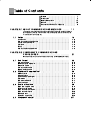
Conventions Used in This Manual
J How This Manual is Organized
Purpose
D
Introduction
Title
%+.", Description
%&-
%+.", ,&"#'2 !"- ,&"-
*(4
(/)& .&*)- (".%*!- )! 1&,&)$
D
CompoWay/F
%+.", *(+*2
%&-
%+.", !"- ,&"- *(+*2
#*,(.
*((/)& .&*)-
D
Communications Data
%+.", %&-
%+.", '&-.- *(+*2
)! 2-12
*((/)& .&*)- !.
D
Sysway
%+.", 2-12
%&-
%+.", !"- ,&"- 2-12
*((/)& .&*)- D
Appendix
J Related Manuals
%&- -",- )/' !"- ,&"- .%"
*((/)& .&*)- #/) .&*)- *# .%" *, !".&'- *) .%" #/) .&*)- *# " % *# .%"-" !&$&.'
*).,*''",- ,"#", .* .%" ,"-+" .&0"
-",- )/'-
V
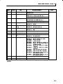
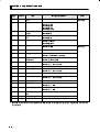
Table of Contents
Preface . . . . . . . . . . . . . . . . . . . . . . . . . . . . . . . . . . . . .
Precautions
.................................
III
Notice . . . . . . . . . . . . . . . . . . . . . . . . . . . . . . . . . . . . . .
IV
Conventions Used in This Manual . . . . . . . . . . . . . .
V
1Ć1
This chapter briefly describes the supported communications methods and how to
wire equipment. FirstĆtime users should read this chapter without fail to ensure propĆ
er installation of the equipment.
Outline . . . . . . . . . . . . . . . . . . . . . . . . . . . . . . . . . . . . . . . . . . . . . . . . .
Introduction
1Ć2
........................................................
1Ć2
Communications specifications . . . . . . . . . . . . . . . . . . . . . . . . . . . . . . . . . . . . . . . .
1Ć2
Transmission procedure . . . . . . . . . . . . . . . . . . . . . . . . . . . . . . . . . . . . . . . . . . . . . .
1Ć3
Interface . . . . . . . . . . . . . . . . . . . . . . . . . . . . . . . . . . . . . . . . . . . . . . . . . . . . . . . . . . .
1Ć3
Wiring . . . . . . . . . . . . . . . . . . . . . . . . . . . . . . . . . . . . . . . . . . . . . . . . . . . . . . . . . . . . .
1Ć3
Communications parameters
1Ć5
.........................................
CHAPTER 2 COMPOWAY/F COMMUNICATIONS
PROCEDURES . . . . . . . . . . . . . . . . . . . . . . . . . . . .
2Ć1
Read this chapter if you are to communicate using the CompoWay/F format.
2.1
2.2
Data Format
2.3
............................................
2Ć2
BCC calculation example . . . . . . . . . . . . . . . . . . . . . . . . . . . . . . . . . . . . . . . . . . . . .
2Ć3
Response frame . . . . . . . . . . . . . . . . . . . . . . . . . . . . . . . . . . . . . . . . . . . . . . . . . . . .
2Ć3
Communications data . . . . . . . . . . . . . . . . . . . . . . . . . . . . . . . . . . . . . . . . . . . . . . . .
2Ć4
Example of end code . . . . . . . . . . . . . . . . . . . . . . . . . . . . . . . . . . . . . . . . . . . . . . . .
2Ć4
Structure of Command Text . . . . . . . . . . . . . . . . . . . . . . . . . . . . . . .
2Ć6
PDU structure . . . . . . . . . . . . . . . . . . . . . . . . . . . . . . . . . . . . . . . . . . . . . . . . . . . . . .
2Ć6
Area definitions . . . . . . . . . . . . . . . . . . . . . . . . . . . . . . . . . . . . . . . . . . . . . . . . . . . . .
2Ć6
Type code (variable type)
2Ć6
............................................
.........................................................
2Ć7
Number of elements . . . . . . . . . . . . . . . . . . . . . . . . . . . . . . . . . . . . . . . . . . . . . . . . .
2Ć7
List of services . . . . . . . . . . . . . . . . . . . . . . . . . . . . . . . . . . . . . . . . . . . . . . . . . . . . . .
2Ć7
Details of Services . . . . . . . . . . . . . . . . . . . . . . . . . . . . . . . . . . . . . . .
2Ć8
Read from variable area
2.4
2Ć2
Command frame . . . . . . . . . . . . . . . . . . . . . . . . . . . . . . . . . . . . . . . . . . . . . . . . . . . .
Addresses
.............................................
2Ć8
Write to variable area . . . . . . . . . . . . . . . . . . . . . . . . . . . . . . . . . . . . . . . . . . . . . . . .
2Ć9
Read controller attributes . . . . . . . . . . . . . . . . . . . . . . . . . . . . . . . . . . . . . . . . . . . . .
2Ć11
Read controller status
2Ć12
...............................................
Echoback test . . . . . . . . . . . . . . . . . . . . . . . . . . . . . . . . . . . . . . . . . . . . . . . . . . . . . .
2Ć13
Operation instructions
2Ć14
...............................................
Response Code List
II
Safety Precautions . . . . . . . . . . . . . . . . . . . . . . . . . . .
CHAPTER 1 ABOUT COMMUNICATIONS METHODS . . . . . .
1.1
I
.....................................
2Ć17
=
,-5 ',%36)4 /-565 6,) ()6%-/5 2* )%', 2* 6,) '20071-'%6-215 (%6% -1 6,) 2032"%;
%1( ;59%; '20071-'%6-215 342')(74)5
!%4-%&/) 4)% 5)673 4%1+) -56
=
6%675 =
$"$ # =
,)5) '20071-'%6-215 342')(74)5 %4) 5733246)( *24 )1574-1+ '203%6-&-/-6; 9-6,
):-56-1+ 6)03)4%674) '21642//)4 02()/5 . %1( .#
%6% 240%6
200%1( *4%0) *240%6 =
'%/'7/%6-21 ):%03/) =
)53215) *4%0) =
20071-'%6-215 (%6% =
;59%; '200%1( /-565 =
200%1( )5'4-36-215 =
)%( 342')55 8%/7) =
"4-6) 5)6 8%/7)5 =
)%( 5)6 8%/7) %1( ! 021-624 =
20071-'%6-215 94-6-1+ 59-6',-1+ =
# -56 # =
#
=
=
=
CHAPTER 1 ABOUT COMMUNICATIONS METHODS
1
CHAPTER 1
ABOUT
COMMUNICATIONS
METHODS
This chapter briefly describes the supported communications methods
and how to wire equipment. FirstĆtime users should read this chapter
without fail to ensure proper installation of the equipment.
1.1
Outline
. . . . . . . . . . . . . . . . . . . . . . . . . . . . . . .
1Ć2
Introduction . . . . . . . . . . . . . . . . . . . . . . . . . . .
1Ć2
Communications specifications
. . . . . . . . . .
1Ć2
. . . . . . . . . . . . . . . .
1Ć3
Interface . . . . . . . . . . . . . . . . . . . . . . . . . . . . . .
1Ć3
Wiring . . . . . . . . . . . . . . . . . . . . . . . . . . . . . . . .
1Ć3
Communications parameters . . . . . . . . . . . .
1Ć5
Transmission procedure
1-1
CHAPTER 1
1.1
J
ABOUT COMMUNICATIONS METHODS
Outline
Introduction
&# ./-%/+ $-/ 1&# !-++2,'!1'-,0 $2,!1'-,0 /# !/#1#" -, 1&# &-01
!-+.21#/ ," 1&# 0 ./+#1#/0 /# +-,'1-/#" -/ 0#1
$/-+ 1&# &-01 !-+.21#/ &#/#$-/# 1&# "#0!/'.1'-, ./-3'"#" &#/# '0 $/-+
1&# 3'#4.-',1 -$ 1&# &-01 !-+.21#/
-+.-5 '0 0 01,"/" !-++2,'!1'-,0 $-/+1 $-/ %#,#/*
0#/'* !-++2,'!1'-,0 &'0 $-/+1 20#0 01,"/" $/+# $-/+1 0 4#**
0 1&# !-++,"0 4&'!& &3# ./-3#, 02!!#00$2* ', 0 0
&#/#$-/# '1 !, 0'+.*'$5 !-++2,'!1'-,0 #14##, !-+.-,#,10 ," 1&#
&-01 !-+.21#/
!1-/5 ,1#/$!# #14-/) #/3'!#
&# ./-1-!-* ./-3'"#0 +#00%# !-++2,'!1'-,0 #14##, !-,1/-*8
*#/0 ', ,#14-/)0
&# &3# 1&# $-**-4',% !-++2,'!1'-,0 $2,!1'-,0
• #"',%4/'1',% -$ ./+#1#/0
• .#/1'-, ',01/2!1'-,0
• #*#!1'-, -$ 0#12. *#3#*0
-++2,'!1'-,0 /# 02 (#!1 1- 1&# $-**-4',% !-,"'1'-,
J
• /+#1#/0 !, # 4/'11#, -,*5 4&#, 1&# 6!-++2,'!1'-,0 4/'1',%
./+#1#/ '0 0#1 1- #, *#"
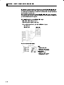
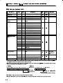
Communications specifications
Transmission line connection
RSĆ485 : Multiple point
RSĆ232C : Point to point
Communications method
*1
RSĆ485 (2Ćwire, halfĆduplex)
RSĆ232C
Synchronization method
StartĆstop synchronization
Baud rate
1200, 2400, 4800, 9600, 19200 bps
Communication code
Data bits
*2
Stop bits
*2
*2
Error detection
ASCII
7 or 8 bits
1 or 2 bits
Vertical parity (non, even, or odd)
FCS (frame check sequence) during Sysway comĆ
munications
BCC (block check character) during CompoWay/F
communications
Flow control
Interface
*1
None
RSĆ485/RSĆ232C
Retry function
None
Communications buffer
40 byte
8 '0 -,*5 3'* *# 4'1& 1&# -++2,'!1'-,0 0.##" "1 '10 01-. '10 ," 3#/1'!* ./'15 !, #!&
# 0#1 ',"#.#,"#,1*5 ', 1&# !-++2,'!1'-,0 0#11',% *#3#* '%&*'%&1#"
!&/!1#/0 ', 1&# 1 *# -3# ',"'!1# "#$2*10
1-2
1.1 Outline
J
Transmission
$ ) %() %#&*)' )'$(#!)( %##$ '# ) )'$(#!)( '(&%$( '# ) ) %''(&%$( )% ) %##$ '#
procedure
(!$" '(&%$( '# !( ')*'$ %' %##$ '# %""%,0
!$ !'# ( %,( ) %&')!%$ % ) %##$ $ '(&%$( '#(
Command frame
Command frame
Host computer
E5AN/EN/CN/GN
Response frame
""%, ,!) )!# % ) "() #( *$)!" ) $-) %##$ !( ($) )' ) %() %#&*)' '!+( '(&%$( '%# ) J
%##*$!)!%$( ,!)
Interface
) %() %#&*)' ' ''! %*) ) '%*
' 0 0
0
!( %$". +!"" ,!)
()$0
) !$)'
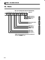
J
RSĆ485
Wiring
•
0 %$$)!%$( $ %' #-!#*# % $!)( !$"*!$
) %() %#&*)' $ %$$) !$ %$0)%0 (.()#(
•
)%)" " "$)
•
( ( !" ),!()0&!' " %' "'' %' ,!'!$ ) !( # #-
$ )% %' ,!'!$ ) Communications transceiver
Host computer
E5AN/EN/CN/GN
RSĆ485
RSĆ485
Abbr
Pin No.
FG
-
AN/EN/CN
+
TX
Abbr
GN
12
6
A(-)
11
5
B(+)
RX
SG
6.8V
Shielded cable
A<B: [1] mark
A>B: [0] space
E5AN/EN/CN/GN
Terminator end node
120Ω
RSĆ485
(1/2W)
Pin No.
Abbr
AN/EN/CN
GN
Both ends of the transmission line
12
6
A(-)
(including the host computer) must be
11
5
B(+)
specified (by setting terminator ON) as
the end node. The total resistance of
the terminators must be at least 54Ω.
Use a terminator of resistance
Shielded cable
120Ω = (1/2W).
1-3
CHAPTER 1 ABOUT COMMUNICATIONS METHODS
,# ,#
,#
(&&-'$,$('+ +) $!$,$('+ (! ,#
'
#(+, (&)-, * ! (' 3,(3 +1+, & $+ $'" -+ &-'$,$('+ +) $!$,$('+ (! %% .$ + $' ,#
-'$, '-& *+ *
#$+ + ,$('
,#
0)%$'+ #(/ ,( + , ,#
(&3
+ (&&-'$,$('+
#(+, (&)-, * * ! * ,( ,#
#(+, (&)-, *
RS-232C (Applies to the E5AN/EN only.)
•
('' ,$('+ *
•
#
,(,% %
•
+
+#$ % ,/$+, )$* %
% '",# $+ & &0
Host computer
RS232C : 25P
(* %*" *
E5AN/EN
Cable reference diagram
E5GN
AWG24 to AWG14
Conductor cross-section
0.2047mm2 to 2.081mm2
E5AN/EN/CN
AWG28 or larger
Conductor cross-section
0.08042mm2 or larger
1-4
,#, ,#
+& +) $!$,$('+ (* ,$%+ (' ,#
)*(.$ /$,# ,#
+-*
+1+, & 0 ), $'$.$-%
+ *+ '-%
1.1 Outline
J
Communications
parameters
Parameter
The E5AN/EN/CN/GN's communications specifications are set in the
communications setting level. These parameters are set on the E5AN/EN/
CN/GN's front panel.
The following table shows the communications parameters and their setĆ
ting ranges.
Displayed
Setting Range
Characters
Set Value
Communications unit No.
0 to 99
Baud rate
1.2 / 2.4 / 4.8 /
Communications data length
7 / 8 (bit)
7 / 8 (bit)
Communications stop bit
1 / 2
1 /2
Communications parity
None / even / odd
0, 1 to 99
9.6 / 19.2 (kbps)
1.2 / 2.4 / 4.8 / 9.6 / 19.2 (kbps)
/
/
Highlighted characters indicate defaults.
F
Communications
parameter setup
Before you carry out communications with the E5AN/EN/CN/GN, set up
communications unit No., baud rate and other parameters by carrying out
the following procedure. For details of operations other than communicaĆ
tions parameter setup, refer to the E5AN/EN/CN/GN User's Manuals.
(1) Hold down the
key for at least three seconds to move from the
operation level" to the initial setting level."
key for less than one second to move from the initial
(2) Press the
setting level" to the communications setting level."
(3) Select the parameters as shown below by pressing the
key.
(4) Use the
or
keys to change the parameter set values.
Communications unit No.
Communications unit No.
Baud rate
Baud rate
Communications unit No.
Communications data
length
Communications data length
Baud rate
Communications stop bit
Communications stop bit
Communications data length
Communications stop bit
Communications parity
Communications parity
Communications parity
E5AN/EN
E5CN
E5GN
1-5
CHAPTER 1 ABOUT COMMUNICATIONS METHODS
F Communications
parameter setup
#' '' #!!("'#"& $%!'%& % " '% '+ ) "
" + %&''" ' #"'%# %
• #!!("'#"& ("' # & $%!'% & #% &''" ' ("' # '# # ' '!$%'(% #".
'%# %& & ("' # & &' &# '' ' #&' #!$('% " "'+ '
'!$%'(% #"'%# % *" #!!("'#"& % %% #(' *' '
#&' #!$('% ' ("' # *'" ' %" '# #% '!$%.
'(% #"'%# % #""' '# ' #&' #!$('% #" ' "'*#% ( '
& , " '*# #% !#% '!$%'(% #"'%# %& % (& # "#' &'
' &! ("' # #" &# * $%)"' "#%! #$%'#"
• ( %' & $%!'% & #% &''" ' ( %' *" #!!("'" *'
' #&' #!$('% ' #" # , $& ,
$& ,
$& , $& " , $&
• #!!("'#"& ' "' & $%!'% & #% &''" ' #!!("'#"& ' "' ' '%
# , '& #% , '&
• #!!("'#"& &'#$ ' & $%!'% & #% &''" ' #!!("'#"& &'#$ ' ' '% #
, #% ,
• #!!("'#"& $%'+ & $%!'% & #% &''" ' #!!("'#"& $%'+ ' #" #
,"#" ,)" #% ,#
1-6
CHAPTER 2 CompoWay/F COMMUNICATIONS PROCEDURES
2
CHAPTER
CHAPTER 2
CompoWay/F
COMMUNICATIONS
PROCEDURES
Read this chapter if you are to communicate using the CompoWay/F
format.
2.1
2.2
2.3
2.4
Data Format . . . . . . . . . . . . . . . . . . . . . . . . . . .
2Ć2
Command frame . . . . . . . . . . . . . . . . . . . . . . .
2Ć2
BCC calculation example . . . . . . . . . . . . . . . .
2Ć3
Response frame . . . . . . . . . . . . . . . . . . . . . . . .
2Ć3
Communications data . . . . . . . . . . . . . . . . . .
2Ć4
Example of end code . . . . . . . . . . . . . . . . . . . .
2Ć4
Structure of Command Text . . . . . . . . . . . . .
2Ć6
PDU structure . . . . . . . . . . . . . . . . . . . . . . . . .
2Ć6
Area definitions . . . . . . . . . . . . . . . . . . . . . . . .
2Ć6
Type code (variable type)
...............
2Ć6
Addresses . . . . . . . . . . . . . . . . . . . . . . . . . . . . .
2Ć7
Number of elements . . . . . . . . . . . . . . . . . . . .
2Ć7
List of services . . . . . . . . . . . . . . . . . . . . . . . . .
2Ć7
Details of Services . . . . . . . . . . . . . . . . . . . . . .
2Ć8
Read from variable area . . . . . . . . . . . . . . . .
2Ć8
Write to variable area . . . . . . . . . . . . . . . . . . .
2Ć9
Read controller attributes . . . . . . . . . . . . . . .
2Ć11
Read controller status . . . . . . . . . . . . . . . . . .
2Ć12
Echoback test . . . . . . . . . . . . . . . . . . . . . . . . . .
2Ć13
Operation instructions . . . . . . . . . . . . . . . . . .
2Ć14
Response Code List
2Ć17
....................
2-1
CHAPTER 2
2.1
COMPOWAY/F COMMUNICATIONS PROCEDURES
Data Format
Unless otherwise indicated, numbers in this manual are expressed in hexĆ
adecimal. Values in double quotation marks, such as 00", are ASCII.
The number underneath each delimiter in a frame indicates the number
of bytes.
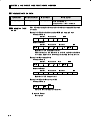
J
Command frame
Text
Node No.
STX
1
SubĆaddress
0
2
0
2
SID
Command text
BCC
0
ETX
1
1
1
BCC calculation range
STX
This code (02) indicates the beginning of the communications frame (text).
Always set this character in the first byte.
When STX is received again during reception, reception is carried out again from
the point where STX was received.
Node number
•
•
•
•
This number specifies the transmission's destination.
Specify the E5AN/EN/CN/GN's Communications unit No.".
BCD range 00" to 99" and XX" can be set.
Specify XX" for a broadcast transmission. No response will be returned for broadĆ
cast transmissions.
•
No responses will be returned from node Nos. set otherwise from the above.
SubĆaddress
This is not used on the E5AN/EN/CN/GN. Be sure to set the subĆaddress to 00".
SID (service ID)
This is not used on the E5AN/EN/CN/GN. Be sure to set the subĆaddress to 00".
Command text
Command text area. For details, see 2.2 Structure of Command Text."
ETX
This code (03) indicates the end of the text.
BCC
Block Check Character
The BCC result is found by calculating the exclusive OR of the bytes from the node
No. up to ETX.
2-2
2.1 Data Format
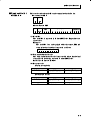
J BCC calculation example
" ! ( %!# # +# %$ # ( %!#
# '$"% # $ # # #& !#!" "## #" # # !
STX
Node No.
02H
SubĆaddress
SID
Command text
0(30H) 0(30H) 0(30H) 0(30H) 0(30H) 0(30H) 5(35H) 0(30H) 3(33H)
BCC=30H
30H
30H
30H
30H
30H
35H
30H
33H
ETX
BCC
03H
35H
03H=35H
Calculation result 35H is set to the BCC area.
The
symbol indicates exclusive OR operation and the H indicates hexadecimal code.
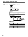
J Response frame
Node No.
SubĆaddress
End code
Command text
STX
1
End
code
BCC
ETX
2
2
2
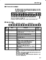
Name
1
1
Error
Detection
Priority
Description
00
Normal completion
The command ended normally without error.
None
0F
FINS command error
The specified FINS command could not be executed.
8
The FINS response code should indicate why the command
could not be executed.
10
Parity error
The sum total of bits whose received data is 1" does not
2
match the set value of communications parity."
11
Framing error
Stop bit is 0".
1
12
Overrun error
An attempt was made to transfer new data when the recepĆ
3
tion data was already full.
13
BCC error
The calculated BCC value is different from the received BCC
5
value.
14
Format error
•
The command text contains characters other than 0 to 9,
7
and A to F. This error is not applicable to the echoback test.
(For details, see chapters 2.3 Echoback test.")
•
•
16
SubĆaddress error
•
•
•
No SID and command text. Or, no command text
MRC/SRC" not included in command text
Illegal (unsupported) subĆaddress
6
No subĆaddress, SID and command text
SubĆaddress less than two characters, and no SID and
command text
18
Frame length error
The received frame exceeds the fixed (supported) number of
4
bytes.
• " !#$! # !% !" !""" # #
" • !" " & !#$! # #" # !" " ! !
# $ # # • )
!!! ## !!#( #" #
!!!" $! "$#$"(
!!#( & #& ! !
2-3
CHAPTER 2
J
COMPOWAY/F COMMUNICATIONS PROCEDURES
Communications data
Communications
specifications
Set (monitor) Value
Minus Value
Decimal point
8 digits (Hex)
2's complement
Decimal point is removed and the result is conĆ
CompoWay/F
!
verted to hexadecimal.
Example) 105.0
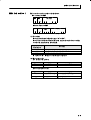
J
Example of end
code
1050
!
000041A
The following examples show an end code when a command did not end
normally.
Example 1) Illegal subĆaddress, and no SID and command text
Command Format
Node No.
STX
BCC
SubĆaddress
0
A
ETX
Response Format
Node No.
STX
SubĆaddress
0
A
BCC
End code
1
6
ETX
End code is 16" (subĆaddress error).
This is because a subĆaddress was received and the subĆaddress
error has a higher error detection priority than the format error.
Example 2) No command text
Command Format
Node No.
STX
SubĆaddress
0
0
SID
0
BCC
ETX
Response Format
Node No.
STX
SubĆaddress
0
0
1
End code is 14" (format error).
Example 3) All node Nos. not provided
Command Format
BCC
STX
ETX
The node No. is lacking one character.
Response Format
No response
2-4
BCC
End code
4
ETX
2.1 Data Format
Example 4) No subĆaddress, and illegal BCC
Command Format
BCC
Node No.
STX
ETX
Err
Response Format
Node No.
STX
SubĆaddress
0
0
BCC
End code
1
3
ETX
SubĆaddress is 00" and end code is 13" (BCC error).
2-5
CHAPTER 2
2.2
J
COMPOWAY/F COMMUNICATIONS PROCEDURES
Structure of Command Text
PDU structure
An MRC (Main Request Code) and SRC (SubĆRequest Code) followed by
the various required data is transferred to the command text.
Service request PDU
MRC
SRC
Data
MRES (Main Response Code) and SRES (SubĆResponse Code) are
transferred following the above MRC/SRC. Data is then transferred
following these MRES and SRES.
Service response PDU (during normal operation)
MRC
SRC
MRES
SRES
Data
If the specified command text could not be executed, only the MRC/
SRC and MRES/SRES become the target response PDUs.
Service response PDU (at nonĆexecution of specified command text)
MRC
SRC
MRES
SRES
MRES/SRES becomes the response code except when processing
ends in normal completion."
J
J
Area definitions
Areas comprise only variable area.
Type code
The following defines variable area type codes.
(variable type)
Variable type (1 byte)
MSB
1
LSB
1
0
0
0
0
Access size
Area
Read/Write
11: DoubleĆword
0: Setup area 0
0: Read only
1: Setup area 1
1: Read/write
The following table summarizes setup areas 0 and 1.
Area
Description
Setup area 0
This area groups together the protect, operation and adjustment
levels.
Setup area 1
This area groups together the initial setting, communications setĆ
ting, advanced function setting and calibration levels.
2-6
2.2 Structure of Command Text
The variable type is converted to 2Ćbyte ASCII code and loaded to the
frame. The following table shows actually existent variable types.
Variable
type
Description
C0
DoubleĆword data. R/O (read only) parameter for setup area 0.
C1
DoubleĆword data. R/W parameter for setup area 0.
C3
DoubleĆword data. R/W parameter for setup area 1.
* Setup area 1 has no R/O (read only) parameters. Therefore, variable type C2" does not exist.
J Addresses
J Number of
elements
J List of services
Each of the variable types is appended with an address. Express addresses
in 2Ćbyte hexadecimal code, and append with its access size.
The number of elements is expressed in 2Ćbyte hexadecimal code. Specify
the number of elements within the range 0 to 2".
For example, when the number of elements is 0002", this specifies two
items of data from the address.
MRC SRC
01
01
Name of service
Read from variable
Process
This service reads from variable areas.
area
01
02
Write to variable area
This service writes to variable areas.
05
03
Read controller
This service reads the model No. and comĆ
attributes
munications buffer size.
Read controller
This service reads the run status of the
status
controller.
06
01
08
01
Echoback test
This service carries out the echoback test.
30
05
Operation
This service carries out run/stop, commuĆ
instructions
nications writing, write mode, save RAM
data, AT (autoĆtuning) execution/cancel,
multiĆSP, move to protect level, move to
setup area 1 and software reset.
* In a memory error (RAM error) or initial state (until the control starts to look for the process
value after the power is turned ON), all commands will not be accepted, and no response will
be returned.
2-7
CHAPTER 2
2.3
J
COMPOWAY/F COMMUNICATIONS PROCEDURES
Details of Services
Read from
variable area
This service reads from variable areas.
Service request PDU
MRC
0
1
SRC
0
2
Variable
Read start
type
address
Bit
position
1
0
2
2
4
Number of
elements
0
2
4
Service response PDU
MRC
0
1
SRC
0
2
Response
Read data
code
(for number of elements)
4
0 or 8 or 16
1
2
(1) Variable type and read start address
For details on variable types and read start addresses, see Chapter 3
Communications Data."
(2) Bit position
Bit accessing is not supported on the E5AN/EN/CN/GN. Fixed to
00".
(3) Number of elements
Number of
Process
elements
0000
Read is not carried out (the service response PDU is not
appended with read data), and processing ends in normal
completion."
0001 to 0002
Read is carried out, and processing ends in normal completion."
(4) Response code
At normal completion
Response code
Name
Description
0000
Normal completion
No errors were found.
At occurrence of error
Response code
Error name
Cause
1001
Command too long
The command is too long.
1002
Command too short
The command is too short.
1101
Area type error
The variable type is wrong.
1103
Start address outĆofĆ
The read start address is
range error
out of range.
Response too long
The number of elements is
110B
larger than 0002".
1100
Parameter error
The bit position is other than
00".
2203
2-8
Operation error
EEPROM error
2.3 Details of Services
(5) Precautions
F Alarm function
Even though alarms are not displayed on the controller's display, they
are all functional in communications.
J Write to variable
area
This service writes to variable areas.
Service request PDU
MRC
0
1
SRC
0
2
Variable
type
Write start
2
4
address
2
2
Bit
position
0
Number of
Write data
elements
(for number of elements)
4
0 or 8 or 16
0
2
Service response PDU
MRC
SRC
0
0
Response
code
1
2
2
2
4
(1) Variable type and write start address
For details on variable types and write start addresses, see Chapter
3 Communications Data."
(2) Bit position
Bit accessing is not supported on the EAN/5EN/CN/GN. Fixed to
00".
(3) Number of elements
Number of
elements
Process
0000
Write is not carried out (the service response PDU is not
appended with write data), and processing ends in normal
completion."
0001 to 0002
Write is carried out, and processing ends in normal completion."
(4) Response code
At normal completion
Response code
Name
Description
0000
Normal completion
No errors were found.
2-9
CHAPTER 2
COMPOWAY/F COMMUNICATIONS PROCEDURES
Response code
Error name
Cause
1002
Command too short
The command is too short.
1101
Area type error
Wrong variable type
1103
Start address outĆofĆ
Write start address is out of range.
range error
1104
End address outĆofĆ
The write end address (write start
range error
address
+
number
of
elements)
exceeds the final address of the variĆ
able area.
1003
1100
Number of elements/
The number of data does not match
data mismatch
the number of elements.
Parameter error
•
•
Bit position is other than 00".
Write data is out of setting range.
3003
ReadĆonly data
Variable type C0" was written to.
2203
Operation error
•
The
communications
writing"
parameter is set to OFF" (disĆ
abled).
•
Writing was
carried
out
on
the
parameters from setup areas 0 to 1.
•
Writing was carried out on a proĆ
tected parameter other than in the
protect level.
•
Writing was carried out during AT
execution.
•
F
! 2-10
$
EEPROM error
" " "
2.3 Details of Services
J Read controller
attributes
This service reads the model No. and communications buffer size.
Service request PDU
MRC SRC
0 5 0 3
2
2
Service response PDU
MRC SRC
Response
code
Model No.
4
10
0 5 0 3
2
2
(1)
CommunicaĆ
tions buffer size
0 0 2 8
4
Model No.
The model No. is expressed in 10Ćbyte ASCII code. Empty bytes are
space codes.
Example :
The model No. for a unit equipped with relay output, HBA and
communications functions is expressed as follows:
E 5 C N Ć R 2 H 0 3
(2)
Communications buffer size
The communications buffer size is expressed in 2Ćbyte hexadecimal
code, and read after being converted to 4Ćbyte ASCII code.
Buffer size: 40 bytes (= H'0028)
(3)
Response code
At normal completion
Response code
Name
Description
0000
Normal completion
No errors were found.
At occurrence of error
Response code
Name
Description
1001
Command too long
The command is too long.
2203
Operation error
EEPROM error
2-11
CHAPTER 2
COMPOWAY/F COMMUNICATIONS PROCEDURES
J Read controller
status
This service reads the run status of the controller.
Service request PDU
MRC
SRC
0
0
6
2
1
2
Service response PDU
MRC
0
6
SRC
0
2
Response
Run
code
status
4
2
Related
informaĆ
tion
1
2
2
(1) Run status
Run status
Description
00
Control is being carried out (error has not occurred in setup area
0, and the controller is running).
01
Control is not being carried out (state other than above).
(2) Related information
7
6
5
0
4
3
0
0
2
1
0
Bit position
Heater overcurrent
Heater current hold
HB (HBA display) error
Display range exceeded
Input error
(3) Response code
At normal completion
Response code
Name
Description
0000
Normal completion
No errors were found.
At occurrence of error
Response code
2-12
Name
Description
1001
Command too long
The command is too long.
2203
Operation error
EEPROM error
2.3 Details of Services
J Echoback test
This service carries out the echoback test.
Service request PDU
MRC
SRC
0
0
8
2
Test data
1
2
0 to 23
Service response PDU
MRC
SRC
Response
Test data
code
0
8
0
2
1
2
0 to 23
(1) Test data
Set any test data within the range 0" to 23".
Set a value for the test data within the ranges shown below according
to the communications data length.
Communications
data length
Test data
8 bits
20 to 7E, A1 to FE converted to ASCII code
7 bits
20 to 7E converted to ASCII code
Do not set 40". Doing so results in no response.
(2) Response code
At normal completion
Response code
Name
Description
0000
Normal completion
No errors were found.
At occurrence of error
Response code
Name
Description
1001
Command too long
The command is too long.
2203
Operation error
EEPROM error
2-13
CHAPTER 2
COMPOWAY/F COMMUNICATIONS PROCEDURES
J Operation
instructions
This service carries out run/stop, communications writing, write mode,
save RAM data, AT (autoĆtuning) execution/cancel, multiĆSP, move to proĆ
tect level, move to setup area 1 and software reset.
Service request PDU
MRC
SRC
InstrucĆ
Related
tion code
informaĆ
tion
3
0
0
2
5
2
2
2
Service response PDU
MRC
SRC
Response
code
3
0
0
2
5
2
4
(1) Instruction code and related information
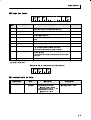
Instruction
code
00
Description
Communications writing
Related information
00: OFF (disabled)
01: ON (enabled)
01
Run/Stop
00: Run
01: Stop
02
MultiĆSP
00: Set point 0
01: Set point 1
02: Set point 2
03: Set point 3
03
AT execute/cancel
00: Cancel
01: AT execute
04
Write mode
00: Backup
01: RAM
05
Save RAM data
00
06
Software reset *
00
07
Move to setup area 1
00
08
Move to protect level
00
* No response will be returned when a software reset is carried out.
(2) Response code
At normal completion
2-14
Response code
Name
Description
0000
Normal completion
No errors were found.
2.3 Details of Services
, (-**' ( **(*
Response code
Error name
Cause
1001
Command too long
The command is too long.
1002
Command too short
The command is too short.
1100
Parameter error
Instruction code and related informaĆ
tion are wrong.
2203
Operation error
•
The
communications
writing"
parameter is set to OFF" (disĆ
abled). However, note that the error
is accepted regardless of the comĆ
munications writing" parameter setĆ
ting (ON/OFF).
•
The
command
cessed.
For
cannot
details,
be
proĆ
see
(3)
Description of operating instrucĆ
tions and precautions" below.
•
EEPROM error
+*"),"(' ( ()*,"(' "'+,*-,"('+ ' )*-,"('+
F (&&-'","('+ /*","'
, ,! 2(&&-'","('+ /*","' )*&,* ,( 2 '% (*
2 "+% (*"' ,( *%, "'(*&,"(' !"+ "'+,*-,"(' '
), , (,! +,-) *+ ' F -',()
, (',*(% ,( 2*-' (* 2+,() (*"' ,( *%, "'(*&,"(' !"+
"'+,*-,"(' ' ), , (,! +,-) *+ ' F 0-,'%
, -,(4,-'"' ,( 20-, (* 2'% (*"' ,( *%,
"'(*&,"(' !"+ "'+,*-,"(' ' ), , +,-) * ('%1 (/4
.* '(, ,!, ' 2()*,"(' **(* "+ '*, "' ,! (%%(/"'
"'+,'+
• !' ,! 2*-'+,() )*&,* "+ +, ,( 2+,()
• !' ,! "'+,*-,"(' "+ "++- "' 2+,-) * • !' ,! (',*(%
F *", &(
, ",!* ,! $-) &( (* /*", &( (*"' ,( *%,
"'(*&,"(' !"+ "'+,*-,"(' ' ), , (,! +,-) *+ ' F -%,"
, (-* +, )("',+ (*!' "' ,! #-+,&', %.% +( ,!, 1(- +/",!
,( +"* +, )("',
2-15
CHAPTER 2
COMPOWAY/F COMMUNICATIONS PROCEDURES
Write mode
Backup mode
Description
Writing is carried out to EEPROM when the parameters in the
operation/adjustment levels (excluding R/O parameters) are
written by communications.
RAM write mode
Writing is not carried out to EEPROM when the parameters
in the operation/adjustment levels (excluding R/O parameĆ
ters) are written by communications. However, note that
parameters can be changed by operating the keys on the
front panel of the controller.
• % * -( * $& ) % *& * "+' $& * '($2
*() % * &'(* &%!+)*$%* #,#) .#+ % '($*()
( -( **% *& • -( * $& ) %# &%#/ -% * 0&$$+% * &%)
-( * % '($*( ) )* *& 0 %#
& -% * 0&$$+% * &%) -( * % '($*( )** % )
% *& 0 )# * '($*() % * &'(* &%!+)*2
$%* #,#) .#+ % '($*() ( -( **% *& ,%
* -( * $& ) )* *& 0 )#
F , *
) %)*(+* &% -( *) * '($*() % * &'(* &%!+)*$%*
#,#) .#+ % '($*() ) %)*(+* &% % '* *
&* )*+' () % F &*-( ()*
) %)*(+* &% ()+$) '(&)) % *( * '&-( ) *+(% ) %)*(+* &% % '* * &* )*+' () % &
()'&%) - ## (*+(% &( * ) &'(* &% %)*(+* &%
F &, *& )*+' ( ) %)*(+* &% $&,) *& 0)*+' ( % % '* * &*
)*+' () % &-,( %&* ** -% 0 % * # )*+'&$$+% 2
* &%) '(&** &% ) )* *& 0
% 0&'(* &% ((&( ) %(* %
$&, *& )*+' ( ) &( %
% * ) $&, ) (( &+* (&$ )*+' ( * )'#/ % *)
* 0 %'+* */' % * 0 % * # )** % #,# % * ) &'(* &%
%)*(+* &% ) ))+ % )*+' ( * )'#/ - ## %&* %
F &, *& '(&** #,#
) %)*(+* &% $&,) *& * 0'(&** #,# % % '* &%#/
% )*+' ( % * ) %)*(+* &% &$$% ) ))+ % )*+' (
% 0&'(* &% ((&( ) %(* % $&, *& )*+' ( ) &( 2
%
2-16
2.4 Response Code List
2.4
Response Code List
At normal completion
Error
Response
Name
code
detection
Description
priority
0000
Normal
No errors were found.
None
Description
detection
completion
At occurrence of error
Error
Response
Name
code
0401
1001
priority
Unsupported
The service function for the relevant
command
command is not supported.
1
Command too
The command is too long.
2
The command is too short.
3
long
1002
Command too
short
1101
Area type error
The variable type is wrong.
4
1103
Start address
The read/write start address is out of
5
outĆofĆrange
range.
error
1104
End address
The write end address (write start
outĆofĆrange
address
error
exceeds the final address of the variĆ
+
number
of
6
elements)
able area.
1003
Number of eleĆ
The number of data does not match
ments/data misĆ
the number of elements.
7
match
110B
Response too
The response exceeds the commuĆ
long
nications buffer size (when larger than
8
number of elements 0002).
1100
Parameter error
•
•
The bit position is other than 00".
9
The write data is out of the setting
range.
•
The instruction code and related
information in the operating instrucĆ
tion is wrong.
3003
ReadĆonly error
Variable type C0" was written to.
10
2203
Operation error
•
11
•
•
The
communications
writing"
parameter is set to OFF" (disabled).
Writing
was
carried
out
on
the
parameters from setup areas 0 to 1.
Writing was carried out on a proĆ
tected parameter other than in the
protect level.
•
Writing was carried out during AT
execution.
•
•
Processing is not possible by operĆ
ating instruction.
EEPROM error
2-17
CHAPTER 3 COMMUNICATIONS DATA
3
CHAPTER 3
COMMUNICATIONS
DATA
This chapter lists the details of each of the communications data in the
CompoWay/F and Sysway communications procedures.
3.1
Variable Area (setup range) List . . . . . . . . .
3Ć2
3.2
Status . . . . . . . . . . . . . . . . . . . . . . . . . . . . . . . .
3Ć8
3-1
CHAPTER 3
3.1
COMMUNICATIONS DATA
Variable Area (setup range) List
The following table lists the variable areas. Items expressed in hexadeciĆ
mal in the Set (monitor) Value" column are the setting range in the ComĆ
poWay/F specifications. Values in parentheses ()" are the actual setting
range. (Refer to these values for the setting range in the Sysway specificaĆ
tions.)
For details of variable areas that are described not in numerical values but
by text, refer to the relevant parameter descriptions.
Variable
type
C0
Address
0000
Item
Process value
Set (monitor) Value
Level
Temperature: Follow the specified range of the senĆ
Operation
sor.
Analog: Scaling lower limit Ć5%FS to scaling upper
limit +5%FS
C0
0001
Status *
See 4.2 Status."
C0
0002
Internal set point *
SP lower limit to SP upper limit
C0
0003
Heater current monitor
00000000 to 00000226 (0.0 to 55.0)
C0
0004
MV monitor (heat)
Standard : FFFFFFCE to 0000041A (Ć5.0 to 105.0)
Heating and cooling: 00000000 to 0000041A
(0.0 to 105.0)
C0
0005
MV monitor (cool)
* Not displayed on the controller display.
3-2
00000000 to 0000041A (0.0 to 105.0)
3.1 Variable Area (setup range) List
Variable
type
C1
Address
0000
Item
Operation/adjustment
Set (monitor) Value
00000000(0):
protection
No restrictions in operation and
Level
Protect
adjustment levels
00000001(1):
Move to adjustment level restricĆ
00000002(2):
Display and change of only PV"
00000003(3):
Display of only PV" and PV/SP"
ted
and PV/SP" parameters enabled
parameters enabled
C1
0001
Initial setting/commuĆ
00000000(0):
nications protection
Move to initial setting/commuĆ
nications setting level enabled
(move to advanced function setĆ
ting level displayed)
00000001(1):
Move to initial setting/commuĆ
nications setting level enabled
(move to advanced function setĆ
ting level not displayed)
00000002(2):
Move to initial setting/commuĆ
nications setting level restricted
C1
0002
Setup change protection
00000000(0):
OFF (changing of setup on conĆ
00000001(1):
ON (changing of setup on conĆ
troller display enabled)
troller display disabled)
C1
0003
Set point
SP lower limit to SP upper limit
C1
0004
Alarm value 1
FFFFF831 to 0000270F (Ć1999 to 9999)
C1
0005
UpperĆlimit alarm 1
FFFFF831 to 0000270F (Ć1999 to 9999)
C1
0006
LowerĆlimit alarm 1
FFFFF831 to 0000270F (Ć1999 to 9999)
C1
0007
Alarm value 2
FFFFF831 to 0000270F (Ć1999 to 9999)
C1
0008
UpperĆlimit alarm 2
FFFFF831 to 0000270F (Ć1999 to 9999)
C1
0008
LowerĆlimit alarm 2
FFFFF831 to 0000270F (Ć1999 to 9999)
C1
000A
Alarm value 3 *
FFFFF831 to 0000270F (Ć1999 to 9999)
C1
000B
UpperĆlimit alarm 3 *
FFFFF831 to 0000270F (Ć1999 to 9999)
C1
000C
LowerĆlimit alarm 3 *
FFFFF831 to 0000270F (Ć1999 to 9999)
C1
000D
Heater burnout detection
00000000 to 000001F4 (0.0 to 50.0)
C1
000E
Set point 0
SP lower limit to SP upper limit
C1
000F
Set point 1
SP lower limit to SP upper limit
C1
0010
Set point 2
SP lower limit to SP upper limit
C1
0011
Set point 3
SP lower limit to SP upper limit
C1
0012
Temperature input shift
FFFFF831 to 0000270F (Ć199.9 to 999.9)
C1
0013
UpperĆlimit temperature
FFFFF831 to 0000270F (Ć199.9 to 999.9)
Operation
Adjustment
input shift value
C1
0014
LowerĆlimit temperature
FFFFF831 to 0000270F (Ć199.9 to 999.9)
input shift value
C1
0015
Proportional band
00000001 to 0000270F (0.1 to 999.9)
C1
0016
Integral time
00000000 to 00000F9F (0 to 3999)
C1
0017
Derivative time
00000000 to 00000F9F (0 to 3999)
C1
0018
Cooling coefficient
00000001 to 0000270F (0.01 to 99.99)
* Only displayed on the E5ENĆV3VVV.
The alarm function can be also be utilized on units without alarm output terminals. In this case, confirm alarm occurrences via the
status data.
3-3
CHAPTER 3
Variable
type
COMMUNICATIONS DATA
Address
Item
Set (monitor) Value
Level
C1
0019
Dead band
FFFFF831 to 0000270F (Ć199.9 to 999.9)
C1
001A
Manual reset value
00000000 to 000003E8 (0.0 to 100.0)
C1
001B
Hysteresis (OUT1)
00000001 to 0000270F (0.1 to 999.9)
C1
001C
Hysteresis (OUT2)
00000001 to 0000270F (0.1 to 999.9)
C3
0000
Input type *
00000000(0):
Pt (Ć200 to 850_C/Ć300 to 1500_F)
00000001(1):
Pt (Ć199.9 to 500.0_C/Ć199.9 to
00000002(2):
Pt (Ć0.0 to 100.0_C/Ć0.0 to 210.0_F)
00000003(3):
Jpt (Ć199.9 to 500.0_C/Ć199.9 to
00000004(4):
Jpt (Ć0.0 to 100.0_C/0.0 to 210.0_F)
00000000(0):
K (Ć200 to 1300_C/Ć300 to 2300_F)
00000001(1):
K (Ć20.0 to 500.0_C/0.0 to 900.0_F)
00000002(2):
J (Ć100 to 850_C/Ć100 to 1500_F)
00000003(3):
J (Ć20.0 to 400.0_C/0.0 to 750.0_F)
00000004(4):
T (Ć200 to 400_C/Ć300 to 700_F)
00000005(5):
E (0 to 600_C/0 to 1100_F)
00000006(6):
L (Ć100 to 850_C/Ć100 to 1500_F)
00000007(7):
U (Ć200 to 400_C/Ć300 to 700_F)
00000008(8):
N (Ć200 to 1300_C/Ć300 to 2300_F)
C3
0001
Scaling upper limit
Adjustment
Initial setting
900.0_F)
900.0_F)
00000009(9):
R (0 to 1700_C/0 to 3000_F)
0000000A(10):
S (0 to 1700_C/0 to 3000_F)
0000000B(11):
B (100 to 1800_C/300 to 3200_F)
0000000C(12):
NonĆcontact
temperature
sensor
0000000D(13):
NonĆcontact
temperature
sensor
0000000E(14):
NonĆcontact
temperature
sensor
0000000F(15):
NonĆcontact
temperature
sensor
00000010(16):
0 to 50mV
(K10 to 70_C)
(K60 to 120_C)
(K115 to 165_C)
(K160 to 260_C)
Scaling lower limit +1 to 0000270F (scaling lower
limit +1 to 9999)
C3
0002
Scaling lower limit
FFFFF831 to Scaling upper limit Ć1 (Ć1999 to scalĆ
ing upper limit Ć1)
C3
0003
Decimal point
00000000 to 00000001 ( 0 to 1)
* The input type can be selected according to the connected sensor. Two input type specifications are supported, platinum resistance
thermometer" and thermocouple and nonĆcontact temperature sensor."
3-4
3.1 Variable Area (setup range) List
Variable
type
Address
Item
Set (monitor) Value
C3
0004
_C/_F selection
00000000(0):_C
C3
0005
SP upper limit
Temperature:
Level
Initial setting
00000001(1):_F
SP lower limit +1 to Input range upper limit
Analog: SP lower limit +1 to scaling upper limit
C3
0006
SP lower limit
Temperature:
Input range lower limit to SP upper limit Ć1
Analog: Scaling lower limit to SP upper limit Ć1
C3
C3
C3
0007
0008
0009
PID/ ON/OFF
00000000(0):
ON/OFF
00000001(1):
2ĆPID
Standard/Heating and
00000000(0):
Standard
cooling
00000001(1):
Heating and cooling
ST
00000000(0):
OFF
00000001(1):
ON
C3
000A
Control period (OUT1)
00000001 to 00000063 (1 to 99)
C3
000B
Control period (OUT2)
00000001 to 00000063 (1 to 99)
C3
000C
Direct/reverse operaĆ
00000000(0):
Reverse operation
tion
00000001(1):
Direct operation
Alarm 1 type
00000000(0):
Alarm function OFF
00000001(1):
UpperĆ and lowerĆlimit alarm
00000002(2):
UpperĆlimit alarm
00000003(3):
LowerĆlimit alarm
00000004(4):
UpperĆ and lowerĆlimit range alarm
00000005(5):
UpperĆ and lowerĆlimit alarm with
00000006(6):
UpperĆlimit
C3
000D
standby sequence
alarm
with
standby
alarm
with
standby
sequence
00000007(7):
LowerĆlimit
sequence
00000008(8):
AbsoluteĆvalue upperĆlimit alarm
00000009(9):
AbsoluteĆvalue lowerĆlimit alarm
0000000A(10):
AbsoluteĆvalue
upperĆlimit
alarm
with standby sequence
0000000B(11):
AbsoluteĆvalue
lowerĆlimit
alarm
with standby sequence
C3
000E
Alarm 2 type
Same as alarm 1 type
C3
000F
Alarm 3 type *
Same as alarm 1 type
* The alarm function can be also be utilized on units without alarm output terminals. In this case, confirm alarm occurrences via the
status data.
3-5
CHAPTER 3
Variable
type
C3
COMMUNICATIONS DATA
Address
0010
Item
Communications unit
Set (monitor) Value
00000000 to 00000063 (0 to 99)
No. *1
C3
0011
Baud rate *
Level
CommunicaĆ
tions setting
1
00000000(0): 1.2
00000001(1): 2.4
00000002(2): 4.8
00000003(3): 9.6
00000004(4): 19.2
C3
C3
C3
0012
0013
0014
Communications data
00000007(7): 7
length *1
00000008(8): 8
Communications stop
00000001(1): 1
bit *1
00000002(2): 2
Communications parity
00000000(0): None
00000001(1): Even
00000002(2): Odd
C3
001A
MultiĆSP
C3
001B
Spare
C3
001C
SP ramp set value
00000000(0): OFF
Advanced funcĆ
00000001(1): ON
tion setting
00000000(0): OFF
00000001 to 0000270F (1 to 9999)
C3
C3
001D
001E
Standby sequence
00000000(0): Condition A
reset method
00000001(1): Condition B
Alarm 1 open in alarm
00000000(0):
Close in alarm
00000001(1):
Open in alarm
C3
001F
Alarm 1 hysteresis
00000001 to 0000270F (0.1 to 999.9)
C3
0020
Alarm 2 open in alarm
00000000(0):
Close in alarm
00000001(1):
Open in alarm
C3
0021
Alarm 2 hysteresis
00000001 to 0000270F (0.1 to 999.9)
C3
0022
Alarm 3 open in alarm*
00000000(0):
Close in alarm
00000001(1):
Open in alarm
C3
0023
Alarm 3 hysteresis
00000001 to 0000270F (0.1 to 999.9)
C3
0024
HBA used
00000000(0):
OFF
00000001(1):
ON
00000000(0):
OFF
00000001(1):
ON
C3
C3
0025
0026
Heater burnout latch
Heater burnout hysterĆ
00000001 to 00001F4 (0.1 to 50.0)
esis
C3
0027
ST stable range
00000001 to 0000270F (0.1 to 999.9)
C3
0028
α
00000000 to 00000064 (0.00 to 1.00)
*1 Communications parameters are enabled after they have been changed by resetting the controller.
* The alarm function can be also be utilized on units without alarm output terminals. In this case, confirm alarm occurrences via
the status data.
3-6
3.1 Variable Area (setup range) List
Variable
type
C3
Address
0029
Item
MV upper limit
Set (monitor) Value
Level
Standard: MV lower limit +0.1 to 000041A
Advanced funcĆ
(MV lower limit +0.1 to 105.0)
tion setting
Heating and cooling: 00000000 to 0000041A
(0.0 to 105.0)
C3
002A
MV lower limit
Standard: FFFFFFCE to MV upper limit Ć0.1
(Ć5.0 to MV upper limit Ć0.1)
Heating and cooling: FFFFFBE6 to 00000000
(Ć105.0 to 0.0)
C3
002B
Input digital filter
00000000 to 0000270F (0.0 to 999.9)
C3
002C
Additional PV display
00000000(0):
OFF
00000001(1):
ON
00000000(0):
OFF (display of manipulated variĆ
00000001(1):
ON
C3
002D
Manipulated variable
display
able OFF)
(display
of
manipulated
variĆ
able ON)
C3
002E
Automatic return of
display mode
C3
C3
C3
C3
002F
0030
0031
0032
Alarm 1 latch
Alarm 2 latch
Alarm 3 latch
Protect level move
00000000(0):
OFF
00000001 to 00000063 (1 to 99)
00000000(0):
OFF
00000001(1):
ON
00000000(0):
OFF
00000001(1):
ON
00000000(0):
OFF
00000001(1):
ON
00000001 to 0000001E (1 to 30)
time
C3
C3
0033
0034
Output input error
Cold junction comĆ
pensation method
C3
0035
MB command logic
switching*
00000000(0):
OFF
00000001(1):
ON
00000000(0):
OFF
00000001(1):
ON
H'00000000(0):
OFF
H'00000001(1):
ON
* The logic is switched only in MB command (Sysway).
The logic of CompoWay/F operation instruction code 00 (communications writing) is not influenced.
3-7
CHAPTER 3
3.2
COMMUNICATIONS DATA
Status
" " 15
0
14
13
12
11
0
10
9
8
7
0
6
5
4
3
0
0
2
1
0
Bit position
Heater overcurrent
HB (HBA) error
Input error
Input error
Display range exceeded
HB
Heater current hold
*1
Control output 1
Control output 2
HB (HBA) output
Output
Alarm output 1
Alarm output 2
Alarm output 3
*2
! %VVVV #
3-8
3.2 Status
31 30 29 28 27 26 25 24 23 22 21 20 19 18 17 16
0
0
0
0
0
0
0
0
0
Bit position
0
Run/Stop
Communications writing
Operating status
Write mode
EEPROM
Setup area
AT execute/cancel
3-9
CHAPTER 3
COMMUNICATIONS DATA
The following shows the status contents.
Bit position
0
Bit Description
Status
Heater overcurrent
*1
0
1
Not generated
Generated
Updated
Hold
Not generated
Generated
1
Heater current hold
2
HB (HBA) error
3
Spare
4
Spare
5
Display range exceeded
Not generated
Generated
6
Input error
Not generated
Generated
7
Spare
8
Control output 1
OFF
ON
9
Control output 2
OFF
ON
10
HB (HBA) output
OFF
ON
11
Spare
12
Alarm output 1
OFF
ON
13
Alarm output 2
OFF
ON
OFF
ON
Backup mode
RAM write mode
*2
*3
14
Alarm output 3
15
Spare
16
Spare
17
Spare
18
Spare
19
Spare
20
Write mode
21
EEPROM
22
Setup area
Setup area 0
Setup area 1
23
AT execute/cancel
AT canceled
AT execution in
RAM=EEPROM
RAM
EEPROM
progress
24
Run/Stop
25
Communications writing
26
Spare
27
Spare
28
Spare
29
Spare
30
Spare
31
Spare
Run
Stop
OFF (disabled)
ON (enabled)
*1 1" is set and the heater current is held at the immediately previous current value when
the control output ON time is less than 190 ms.
*2 Whenever the control output is the current output, this is OFF.
*
3-10
Spare" bits are always OFF.
CHAPTER 4
Sysway (E5
J,
X format) COMMUNICATIONS PROCEDURES
4
CHAPTER
CHAPTER 4
Sysway (E5
J,
X
format)
COMMUNICATIONS
PROCEDURES
These communications procedures are supported for ensuring compatiĆ
bility with existing temperature controller models E5
4.1
4.2
j
J and E5
j
X.
Data Format . . . . . . . . . . . . . . . . . . . . . . . . . . .
4Ć2
Command frame format
. . . . . . . . . . . . . . . .
4Ć2
FCS calculation example . . . . . . . . . . . . . . . .
4Ć2
Response frame . . . . . . . . . . . . . . . . . . . . . . . .
4Ć3
Communications data
. . . . . . . . . . . . . . . . . .
4Ć3
Sysway command lists . . . . . . . . . . . . . . . . . .
4Ć4
Command Descriptions . . . . . . . . . . . . . . . . .
4Ć5
Read process value . . . . . . . . . . . . . . . . . . . . .
4Ć5
Write set value . . . . . . . . . . . . . . . . . . . . . . . . .
4Ć6
Read set value and MV monitor
4Ć7
. . . . . . . . .
Communications writing switching
. . . . . .
4Ć8
4-1
"
4.1
J
!&!$& % " #"! #
!
Data Format
Command frame format
CommuĆ
Header
'9'
nications
code
)4*+
"+=9
!
"+72/A
3'947
unit No.
CR
! )'1):1'9/43 7'3-+
.'7')9+7 9.'9 /3*/)'9+8 9.+ 89'79 4, (14)0 ,472'9
422:3/)'9/438
3:2(+7 </9./3 9.+ 7'3-+ 94 )'3 (+ 8+9 /3 4
:3/9 4
7+85438+ </11 (+ 7+9:73+* /, ' 3:2(+7 49.+7 9.'3 9./8 /8 8+9
+'*+7 )4*+
A).'7')9+7 '15.'(+9 )4*+ 9.'9 /3*/)'9+8 9.+ )422'3* 9>5+
'9' )4*+
!+9 ? 431> <.+3 7+'*/3- '3* <7/9/3- '1'72 ;'1:+ 9.+7A
</8+ 8+9 ?
"+=9
"./8 '7+' 8947+8 7+'* ;'1:+8 <7/9+ ;'1:+8 '3* 89'9:8 ".+ )43A
9+39 4, 9./8 '7+' ;'7/+8 '))47*/3- 94 9.+ )422'3*
!
".+ ! 7'2+ .+)0 !+6:+3)+ /8 ,472+* (> )43;+79/3- 9.+
;'1:+ 4(9'/3+* (> )43;+79/3- 9.+ +=)1:8/;+ 4, 94 9.+ 1'89
9+=9 ).'7')9+7 /394 ! ).'7')9+78
"+72/3'947
3*/)'9+8 9.+ +3* 4, 9.+ (14)0 ,472'9
4257/8+8 ? '3* J
.'7')9+7
+9:73 FCS calculation example
The FCS is formed by converting the 8Ćbit value obtained by converting
the exclusive OR of start character @" up to the last text character into
two ASCII characters, and setting this to the FCS area.
!9'79
).'7')9+7
422:3/)'9/438
:3/9 4
! +'*+7 )4*+
%
'9' )4*+
!
'1):1'9/43 7+8:19 /8 )43;+79+* 94 ! '9 +'). */-/9 '3* 8+9 94 9.+ ! '7+'
!
!
".+
8>2(41 /3*/)'9+8 +=)1:8/;+ 45+7'9/43 '3* 9.+ /3*/)'9+8 .+='*+)/2'1 )4*+
4.1 Data Format
J
Response frame
CommuĆ
nications
unit No.
Header
End
code
code
Text
FCS
@
End
10
Parity error
nator
*
Name
code
TermiĆ
CR
Description
Priority
The sum total of bits whose received data is 1" does not
1
match the set value of communications parity."
11
Framing error
Stop bit is 0".
2
12
Overrun error
An attempt was made to transfer new data when the recepĆ
3
tion data was already full.
13
FCS error
The calculated FCS value is different from the received FCS
4
value.
IC*
Undefined error
The header code of the command cannot be interpreted.
5
14
Format error
•
The command length is incorrect.
6
0D
NonĆexecutable command
•
The set value was written when the communications writĆ
7
•
15
•
Undefined data value
•
ing" parameter was set to OFF" (disabled).
The set value was written during AT execution.
The write data is either outside the setting range or not a
8
numerical value.
The data is either outside the setting range or not a numeriĆ
cal value.
00
Normal completion
The command ended normally without error.
Ċ
* The response format for an undefined error" differs from the regular response format in that an error code not an end code" is
stored to the header code."
Response format in the case of an undefined error
CommuĆ
Header
nications
code
FCS
TermiĆ
nator
unit No.
@
J
I
C
*
CR
Communications data
Communications
Set (monitor)
specifications
Value
Sysway
Four digits
(decimal)
Minus Value
If the uppermost digit is Ć1", the
!
uppermost digit is set to A".
Example) Ć1999
A999
Decimal Point
!
The decimal point is removed.
Example) 105.0
1050
If the uppermost digit is Ć", the
!
uppermost digit is set to F".
Example) Ć10
F010
4-3
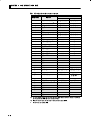
#! "("&( ' !# $#" !$!"
J
Sysway command lists
Category
866=72,*<287; ?:2<B
270 ;.5.,<287
&:2<. 68-. ;.5.,<287
"*>. :=7*-3=;<6.7<
;.< >*5=.
&:2<. ;.< >*5=.
!.*- ;.< >*5=. *76*729=5*<.- >*:2*+5.
6872<8:
!.*- " =99.: *758?.: 5262< >*5=.;
!.*- 9:8,.;; >*5=.
!.*- 272<2*5 ;<*<=;
Header
Data
code
code
Command
".5.,< ,866=72,*<287; ?:2<270
&
&"
&
&
&
&
&%
&
&&
!"
!
!
!
!
!%
!
!&
!
!
".5.,< +*,4=9 68-.
".5.,< ! ?:2<. 68-.
"*>. 89.:*<287*-3=;<6.7< ;.<
>*5=.
&:2<. ;.< 9827<
&:2<. *5*:6 >*5=. &:2<. *5*:6 >*5=. &:2<. 9:898:<287*5 +*7&:2<. 27<.0:*5 <26.
&:2<. -.:2>*<2>. <26.
&:2<. <.69.:*<=:. 279=< ;12/< >*5=.;
&:2<. 1.*<.: +=:78=< -.<.,<287
!.*- ;.< 9827<
!.*- *5*:6 >*5=. !.*- *5*:6 >*5=. !.*- 9:898:<287*5 +*7!.*- 27<.0:*5 <26.
!.*- -.:2>*<2>. <26.
!.*- 279=< ;12/< >*5=.;
!.*- <.69.:*<=:. 1.*<.: +=:78=<
-.<.,<287
!.*- % 6872<8:
!.*- " =99.: *7- 58?.: 5262< >*5B
=.;
!'
!)
!$
!.*- <1. 9:8,.;; >*5=.
!.*- <1. 1.*<.: ,=::.7< 6872<8:
!.*- <1. 272<2*5 ;<*<=;
R/W
Data
Remarks
length
&
&
87.
&
!
!
!
!
!.*- +8<1
=99.:58?.:
5262< >*5=.; *<
87,.
* In a memory error (RAM error) or initial state (until the control starts to look for the process value after the power is turned ON),
no commands will be accepted, and no response will be returned.
* When writing is carried out when a memory error (RAM error) has occurred, writing to EEPROM is not carried out, and processing
ends in normal completion." Reading is as normal.
*1 Status
*2 Status
2< 98;2<287 2< 98;2<287
>.:/58?
87<:85
68-.
2;95*@ 185=<9=< 89.:*<287
2:.,< 89.:*<287:.>.:;. 89.:*<287
* Overflow: Set 1 when the heater current value is greater than 55.0 A.
* Display hold: Set 1 when the control output ON time is less than 190 ms. The previous heater current value is held.
4.2 Command Descriptions
4.2
J
Command Descriptions
Read process
value
This command reads the process value and status.
Command Format
CommuĆ
Header
Data
code
code
nications
unit No.
@
R
X
0
FCS
1
TermiĆ
nator
CR
*
Response Format
CommuĆ
Header
End
Process
code
code
value
nications
unit No.
@
R
Status
TermiĆ
FCS
nator
X
*
CR
(1) Process value
See Chapter 3 Communications Data."
(2) Status
15
14
13
0
0
12
11
10
0
9
8
7
6
0
0
5
4
3
0
0
2
1
0
0
0
Bit position
Input error
Heater burnout
detection
EEPROM
Alarm 1
Alarm 2
Write mode
Communications
writing
Description
Item
0
1
Input error
Not generated
Generated
Heater burnout detection
OFF or does not function
ON
EEPROM
RAM=EEPROM
RAM
Alarm 1
OFF or does not function
ON
Alarm 2
OFF or does not function
ON
Write mode
Backup mode
RAM write mode
Communications writing
OFF (disabled) or does
ON (enabled)
EEPROM
not function
4-5
#!# " & '
"& ," & ' #+ 1 ,"#+ #&#,+ &'*%$ '%($,#'& ' ,"
'%%& ,"*/#+ ," '%%& '-$ &', (*'++ '*
,#$+ '& & '+ + 1+('&+ *% '& (! 4
*-,#'&+
• .& ,"'-!" $*%+ & * &', #+($0 '& ," '&,*'$$*+ #+4
($0 ,"0 * $$ -&,#'&$ #& '%%-&#,#'&+
• "& ," '&,*'$$* "+ %'. ,' +,,#&! * ," (*.#'-+ +,, #+
"$ 1,,#&! * #+ /"* ," #&#,#$ +,,#&! '%%-&#,#'&+
+,,#&! .& -&,#'& +,,#&! & $#*,#'& $.$+ * !*'-(
,'!,"*
J Write set values
"#+ '%%& /*#,+ ," +, ('#&, $*% .$-+ & (*'('*,#'&$
& #&,!*$ ,#% *#.,#. ,#% ,%(*,-* #&(-, +"# , .$-+ &
",* -*&'-, ,,#'&
0..$/' 02.$4
CommuĆ
Header
nications
code
unit No.
$4$ !2,4( 6$-5( (2.,8
&0'(
/$402
CR
(310/3( 02.$4
CommuĆ
Header
nications
unit No.
code
/' (2.,8
&0'(
/$402
CR
* '
Header Code
!
!
!
!
!
!
!!
Command
!2,4( 3(4 10,/4
!2,4( $-$2. 6$-5( !2,4( 1201024,0/$- %$/'
!2,4( ,/4(*2$- 4,.(
!2,4( '(2,6$4,6( 4,.(
!2,4( 4(.1(2$452( ,/154 3+,)4 6$-5(3
!2,4( +($4(2 %52/054 '(4(&4,0/
, '
&$0 1/*#, ,' $*% .$- #+ +, ,' 1 $$ ',"* +,,#&!+ *
1
*#, .$-
'* ,#$+ '& ," /*#, .$- +, .$- *&! + 1"(,* '%4
%-&#,#'&+ ,
*-,#'&+
F $*% .$-+ & "& 1$*% ,0( #+ +, ,' '& ' 1-((*$'/*4$#%#, $*% 1-((*
$'/*4$#%#, *&! $*% '* 1-((*$'/*4$#%#, $*% /#," +,&0
+)-& 1$*% .$- #+ #+$ + ," -((* & $'/* $#%#,+ '
," $*% * +, #&(&&,$0 1((*4$#%#, $*% .$- & 1$'/4
*4$#%#, $*% .$- '% ," $*% +, .$-+
4.2 Command Descriptions
F
#% '& %&#" *" ,($$% #*%/ !' %! & &' *%' ) (& %
*%''" + #!!("'#"& '# ,($$%/ !' %! ) ( " , #*%/
!' %! ) ( " "#' '# , %! ) ( &! $$ & '#
, %! '+$
!$%'(% "$(' &' ) (&
" ,"$(' '+$ & &' '# ,"#"/#"'' '!$%'(% &"&#% ,'!/
$%'(% "$(' &' ) (& & & & '!$%'(% "$(' & &'
+ /$#"' &' ) (& &' '# ' ,($$%/ !' '!$%'(% "$('
&' ) ( " , #*%/ !' '!$%'(% "$(' &' ) ( $%!/
'%& % ' &' ) (& (& #% '!$%'(% "$(' &'
#% '& %&#" *" /$#"' &' & #$' *%' ) (& % *%''"
+ #!!("'#"& '# ,($$%/ !' '!$%'(% "$(' &' ) ( "
, #*%/ !' '!$%'(% "$(' &' ) ( " "#' '# ,'!$%'(%
"$(' &' ) (&
F %!&
%!& " " (& "#%! + " #!!("'#"& #*)%
%! ""#' (&
J Read set value
and MV monitor
& #!!" %& ' &' $#"' %! ) (& " $%#$#%'#"
" "'% '! %)') '! '!$%'(% "$(' &' ) (&
'% (%"#(' ''#" " !#"'#%
Command Format
CommuĆ
nications
@
unit No.
Data FCS TermiĆ
code
nator
Header
code
Response Format
CommuĆ
nications
@
unit No.
*
CR
End Write value FCS TermiĆ
code
nator
Header
code
*
CR
% #
Header Code
RS
R%
RB
RN
RV
RI
RW
RO
Command
Read set point
Read alarm value 1/2
Read proportional band
Read integral time
Read derivative time
Read input shift values
Read temperature heater burnout detection
Read MV monitor
' #
" + ,*%' '# %! ) ( & &' '# ,
#'% &''"& %
,
) (
#% ' & #" ' % ) ( &' ) ( %" & ,$'% #!/
!("'#"& '
4-7
CHAPTER 4
SYSWAY (E5
J,
X FORMAT) COMMUNICATIONS PROCEDURES
),+"&%*
F #)$ -#,* % !% 0#)$ +/' "* *+ +& &% & 0,'')#&.)2#"$"+ #)$ 0,'')
#&.)2#"$"+ )% #)$ &) 0,'')#&.)2#"$"+ #)$ ."+! *+%/
*(,% 0#)$ -#, "* "*# * +! ,'') % #&.) #"$"+* &
+! #)$ ) *+ "%'%%+#/ 0'')2#"$"+ #)$ -#, % 0#&.2
)2#"$"+ #)$ -#, &$ +! #)$ *+ -#,*
&) +!"* )*&% .!% 0,'')#&.)2#"$"+ #)$ "* *+ +! -#, &
0,'')2#"$"+ #)$ -#, % %&+ 0#)$ -#, "* +! -#, )
/ &$$,%"+"&%*
! *$ ''#"* +& 0#)$ +/'
F $')+,) "%',+ *!"+ -#,*
!% 0"%',+ +/' "* *+ +& 0%&%2&%++ +$')+,) *%*&) 0+$2
')+,) "%',+ *!"+ -#,* "* "*# * +$')+,) "%',+ "* *!"+
/ 2'&"%+ *!"+ ! -#,* *+ +& +! 0,'')2#"$"+ +$')+,) "%',+
*!"+ -#, % 0#&.)2#"$"+ +$')+,) "%',+ *!"+ -#, ')$2
+)* ) +! *+ -#,* ,* &) +$')+,) "%',+ *!"+
&) +!"* )*&% .!% 2'&"%+ *!"+ "* &'+ +! -#, & 0,'')2#"$"+
+$')+,) "%',+ *!"+ -#, % %&+ 0+$')+,) "%',+ *!"+ -#2
,* "* +! -#, ) / &$$,%"+"&%*
F #)$*
#)$* % % ,* %&)$##/ "% &$$,%"+"&%* &.-)
#)$ %%&+ ,*
J Communications
writing switching
! #& " & +! &$$% !% * * *!&.% "% +! +# #&. &)2
"% +& +! &$$% #& " *."+!"% *++"% -% ,%+"&% #-#
! &$$% &$$,%"+"&%* .)"+"% *."+!"% "* (,"-#%+ +&
+! &$$% )$&+#&# *."+!"% &% +! j
Text Data of
MB Command
MB Command Logic Switching Setting
OFF
ON
Communications
0000
0001
writing disabled
(remote mode selection)
(local mode selection)
Communications
Communications
writing disabled
writing enabled
(local mode selection)
(remote mode selection)
• &$$% #& " *."+!"% ,#+
*$ #& " * j
4-8
Communications
writing enabled
APPENDIX
APPENDIX
ASCII List
. . . . . . . . . . . . . . . . . . . . . . . . . . . . . . . . .
AĆ2
A-1
//$-#(7
@
@
@
@
@
#
@
@
@
/
‘
N
0
?
O
"
@
@
@
@
-4+
#$+
SPACE
2.'
#"
237
#"
”
!
1
@
P
$37
#"
"
2
A
Q
$.3
#"
#
3
B
R
$-0
-
*
$
4
C
S
"*
28-
%
5
D
T
!$+
$3!
’
&
6
E
U
!2
"
'
7
F
V
'3
$-
(
8
G
W
+%
24!
)
9
H
X
!
53
$2"
*
:
I
Y
"
%%
%2
+
;
J
Z
#
"1
&2
^
,
<
K
[
$
2.
12
-
=
L
\
%
2(
42
.
>
M
#$+
1
$TCL N?PGRW
-
I
A
B
C
NDEX
Addresses . . . . . . . . . . . . . . . . . . . . . . . . . . .
2Ć7
Area definitions . . . . . . . . . . . . . . . . . . . . . .
2Ć6
ASCII list . . . . . . . . . . . . . . . . . . . . . . . . . . . AĆ2
L
N
BCC . . . . . . . . . . . . . . . . . . . . . 1Ć2, 2Ć2, 2Ć3, 2Ć5
O
Command descriptions . . . . . . . . . . . . . . .
P
2Ć6, 2Ć11
Command text . . . . . . . . . . . . . . . . . . . . 2Ć2, 2Ć6
Read controller attributes . . . . . . . .
2Ć7, 2Ć11
Communications data . . . . . . . . . 2Ć4, 3Ć1, 4Ć3
Read controller status . . . . . . . . . . .
2Ć7, 2Ć12
Communications data length . . . 1Ć5, 1Ć6, 3Ć6
Read from variable area . . . . . . . . . . . 2Ć7, 2Ć8
Communications methods . . . . . . . . . . 1Ć1, 1Ć2
Read initial status . . . . . . . . . . . . . . . . . . . .
Communications parameters . . . . . . . . . .
Read process value . . . . . . . . . . . . . . . . 4Ć4, 4Ć5
4Ć2
R
1Ć5
4Ć4
Communications parity . . . . . . . . 1Ć5, 1Ć6, 3Ć6
Read set value and MV monitor . . . . . . . .
4Ć7
Communications specifications . . . . . 1Ć2, 1Ć4
Read SP upper and lower limit values . .
4Ć4
Communications stop bit . . . . . . 1Ć5, 1Ć6, 3Ć6
Response code list . . . . . . . . . . . . . . . . . . . 2Ć17
Communications writing switching . . . .
4Ć8
CompoWay/F . . . . . . . . . . . . . 1Ć2, 2Ć1, 3Ć1, 3Ć2
S
Details of services . . . . . . . . . . . . . . . . . . . .
Echoback test . . . . . . . . . . . . . . . . . . .
ETX . . . . . . . . . . . . . . . . . . . . . . . . . . . . . 2Ć2, 2Ć3
FCS . . . . . . . . . . . . . . . . . . . . . . . . . . . . . 4Ć2, 4Ć3
FCS calculation example . . . . . . . . . . . . . .
4Ć2
FINS . . . . . . . . . . . . . . . . . . . . . . . . . . . . 1Ć2, 2Ć3
Interface . . . . . . . . . . . . . . . . . . . . . . . . . 1Ć2, 1Ć3
SID . . . . . . . . . . . . . . . . . . . . . . . . . . . . . . 2Ć2, 2Ć4
3Ć8
STX . . . . . . . . . . . . . . . . . . . . . . . . . . . . . 2Ć2, 2Ć4
2Ć8
2Ć7, 2Ć13
Response frame . . . . . . . . . . . . . . . . . . . 2Ć3, 4Ć3
Status . . . . . . . . . . . . . . . . . . . . . . . . . . . . . .
Data format . . . . . . . . . . . . . . . . . . . . . . 2Ć2, 4Ć2
T
End code . . . . . . . . . . . . . . . . . 2Ć3, 2Ć4, 4Ć6, 4Ć7
I
2Ć7
PDU . . . . . . . . . . . . . . . . . . . . . . . . . . .
4Ć5
Communications unit No. . . . . . . 1Ć5, 1Ć6, 3Ć6
F
Number of elements . . . . . . . . . . . . . . . . . .
2Ć7, 2Ć15
Command frame format . . . . . . . . . . . . . .
E
2Ć7
Operation instructions . . . . . . . . . .
Command frame . . . . . . . . . . . . . . . . . . 1Ć3, 2Ć2
D
List of services . . . . . . . . . . . . . . . . . . . . . . .
V
W
Sysway command lists . . . . . . . . . . . . . . . .
4Ć4
Transmission procedure . . . . . . . . . . . . . .
1Ć3
Type code (variable type) . . . . . . . . . . . . .
2Ć6
Variable area (setup range) list . . . . . . . .
3Ć2
Wiring . . . . . . . . . . . . . . . . . . . . . . . . . . . . . .
1Ć3
Write set values . . . . . . . . . . . . . . . . . . . . . .
4Ć6
Write to variable area
. . . . . . . . . . . . . 2Ć7, 2Ć9
Revision History
A manual revision code appears as a suffix to the catalog number on the front cover of the manual.
Cat. No. H102ĆE1Ć3
Revision code
The following table outlines the change made to the manual during each revision. Page numbers refer
to previous version
Revision code
Data
Revised content
1
October 1998
Original production
2
March 1999
All pages:
Changed E5CN/GN" to E5EN/CN/GN".
Page III:
Modified the torque value.
Page IV:
Modified (6)" in NOTICE".
Page 1Ć2:
Modified the table and note in Communications
Page 1Ć3:
Modified the diagram in Wiring".
Page 1Ć4:
Added RSĆ232C" description.
Page 1Ć5:
Added the E5EN diagram in Communications
specifications".
parameter setup".
Page 2Ć11: Modified the example in (1) Model No.".
Page 2Ć16: Deleted Note".
Page 3Ć1:
Replace Chapter 3" to Chapter 4".
Page 3Ć3:
Added Note".
Page 3Ć4:
Modified the set value in Scaling lower limit".
Page 3Ć5:
Added Note".
Page 3Ć7:
Added Note".
Page 3Ć7:
Changed C1" to C3" in variable type.
Page 3Ć7:
Modified the set value in MV lower limit".
Page 3Ć8:
Added Notes".
Page 3Ć10: Modified the status contents.
3
April 2000
All pages:
Changed
E5/EN/CN/GN"
to
E5AN/EN/CN/
GN".
Page 1-2:
Modified the item of Transmission line connecĆ
tion" on the table.
Page 3-6 to 3-7: Modified Variable Area (setup range) List".
Page 4-8:
Added Communications writing switching".
OMRON ELECTRONICS LLC
1 Commerce Drive
Schaumburg, IL 60173 USA
800.55.OMRON (66766)
OMRON CANADA, INC.
885 Milner Avenue
Scarborough, Ontario M1B 5V8
416.286.6465
OMRON ON-LINE
Global - http://www.omron.com
USA - http://www.omron.com/oei
Canada - http://www.omron.com/oci
H102-E1-3
Printed in U.S.A.
©2002 OMRON ELECTRONICS LLC
Specifications subject to change without notice.