1
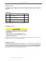
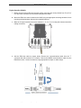
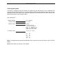
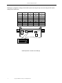
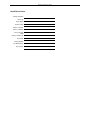
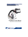
EM1005X Engine Interface Module Installation & User Manual Replaces i8305 used on LP/LY2/JH Yanmar Engines MBW Technologies , LLC Email: [email protected] Phone: (267) 932.8573 x340 www.mbwtech.com EM1005X- Installation/User Manual MBW Technologies, LLC (2 – Year) Limited Warranty Electronic Modules and Displays MBW Technologies, LLC (“MBW”) warrants its Electronic Module and Display products to be free from defects in materials and workmanship for a period of two (2) years from the date of shipment by MBW. Within this period, MBW will, at its sole option, repair or replace any Electronic Module or Display that fails in normal use and is returned to MBW (freight prepaid) within the warranty period. MBW is not responsible for charges connected with the removal of such product or reinstallation of replacement or repaired parts. This warranty does not cover failures due to abuse, misuse, accident, faulty installation or unauthorized alteration or repairs. THE EXPRESS WARRANTY SET FORTH ABOVE IS IN LIEU OF ALL OTHER WARRANTIES, EXPRESS OR IMPLIED, INCLUDING BUT NOT LIMITED TO THE IMPLIED WARRANTIES OF MERCHANTABILITY AND FITNESS FOR A PARTICULAR PURPOSE. Statements made by any person, including representatives of MBW, which are inconsistent or in conflict with the terms of this Limited Warranty, shall not be binding upon MBW unless reduced to writing and approved by a manager of MBW. IN NO EVENT SHALL MBW BE LIABLE FOR ANY INCIDENTAL, SPECIAL, INDIRECT, OR CONSEQUENTIAL DAMAGES, WHETHER RESULTING FROM THE USE, MISUSE OR INABILITY TO USE THIS PRODUCT OR FROM DEFECTS IN THE PRODUCT. Some states do not allow the exclusion of incidental or consequential damages, so the above limitation may not apply to you. MBW retains the exclusive right to repair or replace the electronic module or display or offer a full refund of the purchase price at its sole discretion. SUCH REMEDY SHALL BE YOUR SOLE AND EXCLUSIVE REMEMDY FOR ANY BREACH OF WARRANTY. MBW Technologies, LLC (1 – Year) Limited Warranty Cables and Connectors MBW Technologies, LLC (“MBW”) warrants its Electrical Cable and Connector products to be free from defects in materials and workmanship for a period of one (1) year from the date of shipment by MBW. Within this period, MBW will, at its sole option, repair or replace any electrical cable or connector that fails in normal use and returned to MBW (freight prepaid) within the warranty period. MBW is not responsible for charges connected with the removal of such product or reinstallation of replacement or repaired parts. This warranty does not cover failures due to abuse, misuse, accident, faulty installation or unauthorized alteration or repairs. THE EXPRESS WARRANTY SET FORTH ABOVE IS IN LIEU OF ALL OTHER WARRANTIES, EXPRESS OR IMPLIED, INCLUDING BUT NOT LIMITED TO THE IMPLIED WARRANTIES OF MERCHANTABILITY AND FITNESS FOR A PARTICULAR PURPOSE. Statements made by any person, including representatives of MBW, which are inconsistent or in conflict with the terms of this Limited Warranty, shall not be binding upon MBW unless reduced to writing and approved by a manager of MBW. ® NMEA 2000 is a registered trademark of the National Marine Electronics Association. IN NO EVENT SHALL MBW BE LIABLE FOR ANY INCIDENTAL, SPECIAL, INDIRECT, OR CONSEQUENTIAL DAMAGES, WHETHER RESULTING FROM THE USE, MISUSE OR INABILITY TO USE THIS PRODUCT OR FROM DEFECTS IN THE PRODUCT. Some states do not allow the exclusion of incidental or consequential damages, so the above limitation may not apply to you. MBW retains the exclusive right to repair or replace the cable or connector or offer a full refund of the purchase price at its sole discretion. SUCH REMEDY SHALL BE YOUR SOLE AND EXCLUSIVE REMEMDY FOR ANY BREACH OF WARRANTY. Warranty Return Procedure: To obtain warranty service, contact MBW Technical Support Department at (267) 932-8573 x341 or email [email protected] to describe problem and determine appropriate action. 2 Copyright 2010 MBW Technologies, LLC All Rights Reserved EM1005X- Installation/User Manual Table of Contents Product Overview .......................................................................................................... 4 Components ...................................................................................................................... 4 Installing the System..................................................................................................... 4 Making the Connections .......................................................................................................... 4 Engine Interface Module.......................................................................................................... 5 Pre-power Check List ................................................................................................................ 6 Power-up & Initial Configuration ........................................................................................ 6 Dock Side Checkout .................................................................................................................... 6 System Options ............................................................................................................................ 6 Ordering the System ..................................................................................................... 7 Installation Notes: .......................................................................................................... 9 Copyright 2010 MBW Technologies, LLC All Rights Reserved 3 EM1005X- Installation/User Manual Product Overview The EM1005 Product is designed as a Plug ‘N’ Play data monitoring system for Yanmar Mechanical Engines that replaces the Teleflex i8305. Review the “Ordering the System” section for proper unit configuration. Components EM1005X-5X EM, Eng Interface Module 1 per engine MN10009-5X Data Sheet, EM1005X Optional MN10008-5X Manual, Install / User, EM1005X 1 per system M701X Display, Single or Dual (replaces Teleflex i5601) Optional 1000005-XX Buzzer, 12 volt Optional XX: Denotes part number option for length, position or model. Installing the System Before removal of the i8305 verify that the mating connectors are clearly marked from P1 to P6. If not, label each connector prior to disconnecting from the i8305. Making the Connections Each EIM connector is marked with a connector designator, J1, J2, J4, J5 and J6. Match the labels with the corresponding i8305 boat harness connector P1, P2, P4, P5 and P6. The NMEA connection is made directly to the NMEA 2000 Network via the Communications ‘T’ so P3 is not used. Care must be taken as all of the connectors are interchangeable and must be mated based on their designation. The supply power MUST be OFF when interconnecting the system. 4 Copyright 2010 MBW Technologies, LLC All Rights Reserved EM1005X- Installation/User Manual Engine Interface Module 1. Before removal of the i8305 verify that the mating connectors are clearly marked from P1 to P6. If not, label each connector prior to disconnecting from the i8305. 2. Mount the EIM in the same location as the i8305 using the appropriate mounting hardware for the mounting surface/structure with two user supplied fasteners. 3. Mate the 5 engine interface connectors marked J1, J2, J4, J5, J6 routing the harness toward the mating connectors. 4. Add the EIM drop cable as shown below. Remove the communications cable from the ‘T” connector that was mounted in P3 location. Connect the NMEA communications cable from the EM1005x module. Secure the harness using appropriate tie straps or cable clamps. Copyright 2010 MBW Technologies, LLC All Rights Reserved 5 EM1005X- Installation/User Manual Pre-power Check List Wires are free from abrasive and puncturing materials. Network connections appropriately strain relieved and ‘T’ connectors mounted with screw or tie wrapped to secure surface. Harnesses are properly dressed and strain relieved. Check optional connection for fluid level input. If not used secure the harness using proper harness strain relief Power-up & Initial Configuration With final checks complete, turn on the engine and house battery switches. At the main station, turn “ON” the engine ignition via the rocker or keyswitch depending on panel type installed. Turn switch to “On” position. Check the following and repeat for additional engines. Alarm sounds for approximately 2 seconds. All displays light up starting with the splash screen. The engine data should be present on the displays (i.e. Tachometer is 0 RPM) Dock Side Checkout System alarm check sounded when ignition was turned “On”. With engine running, verify that the display(s) are showing proper engine data. System Options The EM1005x Product is designed as a Plug ‘N’ Play data monitoring system for Yanmar Mechanical Engines that replaces the Teleflex i8305 but if it is used with the M700 display additional features are available. 6 Sensor 2 input can be configured for Fuel, Water, Waste or Rudder Angle. A maintenance timer is enabled. Copyright 2010 MBW Technologies, LLC All Rights Reserved EM1005X- Installation/User Manual Ordering the System The i8305 is configured using DIP switches for determining the EIM location; Port or Starboard and configuring the tachometer pulses per revolution (PPR) to match the engine flywheel teeth count. Another parameter stored is the engine hours. Should the EM1005x be ordered without the M701x Display, this data must be defined when placing the order. See Table Below: ENGINE POSITION: ENGINE HOURS: SENDER 2 INPUT: Port or Starboard xxx.x Hours Defaults: Fuel Tank 3 for Port Fuel Tank 4 for Starboard (Can be configured via M701x for Water, Waste, Rudder Angle or “Not Used”.) FLYWHEEL COUNT: 129, 127, 117, 116 or 97 LY2 LP JH4 JH4T YM 129 117 116 127 97 Note 1. A charge alarm will activate the EM1005x alarm output but may not be present on the TFX i5601 display. Note 2. Boost Alarm (over boost) is not available. Copyright 2010 MBW Technologies, LLC All Rights Reserved 7 EM1005X- Installation/User Manual Reading the configuration settings of the i8305 requires removing the top cover and noting the DIP switch settings. See Table below. PPR 97 PPR 114 PPR 116 PPR 117 PPR 127 PPR 129 PORT Switch 5 Switch 4 Switch 3 Switch 1 Off Off Off X Off Off On X Off Off On On On On Off Off Off On Off On X X X X Off STBD On 8 7 6 5 4 3 2 1 ON 8 7 6 5 4 3 2 1 ON i8305 Dip Switch Locations and Settings 8 Copyright 2010 MBW Technologies, LLC All Rights Reserved EM1005X- Installation/User Manual Installation Notes: Existing Installation: Boat Type: Engine Model: System Voltage: Number of Engines: Number of Stations: USA or European Install: Display / Gauge Type: Fluid Tanks: Existing Network: Trim Measurement: Engine Hours: Copyright 2010 MBW Technologies, LLC All Rights Reserved 9 EM1005X- Installation/User Manual MBW Technologies, LLC 2080 Detwiler Rd. Suite 1 Harleysville, PA 19438 Sales: (267) 932-8573 x340 Email: [email protected] Email: [email protected] OR Contact your local Yanmar Dealer P/N MN10008-50 10 Copyright 2010 MBW Technologies, LLC All Rights Reserved