1
TEACHBOX
User's manual for ROB 3i
p + P Elektronik GmbH
Furth I West Germany
TABLE OF CONTENTS
page
5
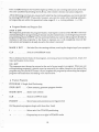
1. Introduction
2. Technical Specifications
6
3. Dimensions and Axis Numbers
7
4. The ROB3i Teachbox
8
5. Operating Modes
9
6. Summary of all Instructions and Commands
10
7. Reference to the Individual Instructions
11
8. Hardware Installation
15
9. Digital Inputs and Outputs, EMERGENCY OFF Function
16
10. Exercises with the Teachbox
17
11. Limited Warranty Terms and Conditions
23
12. Foreign Distributors
24
3
4
1. Introduction
The ROB3i's articulated arm has five axes and a gripper, all of which are powered by DC
servo motors. The absolute position of all axes is determined by potentiometric rotary
position transducers. The ROB3i's contra! system thus always knows the current position of
all axes, even after a power failure.
The robot can be fitted with either an electrical or a pneu matic gripper, making it possible
to perform an extremely wide range of different handling tasks. The integrated control system
automatically identifies the gripper type and controls it accordingly.
The robot's integrated control system can be programmed directly via a special keypad unit,
the Teachbox, using a simple, easy-ta-learn instruction set. The robot is programmed by
entering a sequence of instructions to move the arm to the desired positions; these
instructions are then stored in memory as a control program.
Programs can be delimited or subdivided with labels, which are "address markers" inserted
in the program code. This feature makes it possible to chain individual program units stored
in memory. Subprograms identified by labels can also be called in response to the results of
polling the status of the system's eight digit<\l inputs, making it possible for yOll to program
the ROB3i to respond intelligently to external events. Eight digital outputs are also included,
so that you can program the ROB3i to control its working environment. Bulthat's not all. In
addition, you can choose from five different travel speeds, set delays and repeating or endless
loops, and much more.
For people who enjoy working with computers, the ROB3i is also fitted with an RS-232 serial
interface, making it possible to control and program the robot from any IBM-compatible
personal computer. The software package available for this purpose provides the
programmer with extensive support: It is menu-operated, and all the control language
instructions are permanently displayed on the screen for direct selection. To add an
instruction to the control program you are writing, you simply select it with the cursor keys.
TIlis approach eliminates the possibility of syntax errors. Together with the comprehensive
help texts which can be displayed as needed, all these features give the system an optimally
simple user interface.
For users who wish to develop their own robot control programs, software interfaces are
available in the form of Include files in the languages BASIC, Pascal and C. These Include
files contain subroutines for handling serial interface communication with the robot.
When IBM and Microsoft trademarks are mentioned in the text, this is understood to refer
exclusively to the products of these companies. ROB is a registered trademark of
p + P Elektronik GmbH, Nuremberg, West Germany.
5
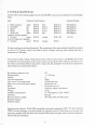
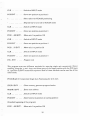
2. Technical Specifications
Travel within the working range of each of the ROB3i's six axes is divided into 512 individual
steps.
Axis
Angular Range
Relative End Position
1
2
3
4
Base rotation
right:
Shoulder
up:
Elbow
up:
\Vrist
up:
5 \Vrist roll
right:
only for electric gripper
open:
6 Gripper
only for pneumatic gripper
6 Gripper
open:
POSO
POSO
POSO
POSO
POSO
left:
down:
down:
down:
left:
POS 511
POS 511
POS 511
POS 511
POS 511
POSO
closed:
POS 100
POSO
closed:
POSl
200
200
200
200
degrees
degrees
degrees
degrees
400 degrees
60mm
All axes can be moved simultaneously. The resolution of the axes makes it possible to access
a total of 512 5 points within the robot's reach. Gripper opening and closing also has a
resolution of 100 steps.
In contrast to other robots, which always have a fixed home position, the ROB3i allo\',.·s you
to redefine the start position at the heginning of each program. This makes it possible to use
the robot in the most difficult situations imaginable, for example \vhen the home position is
obstructed by an immovable object.
Resolution, steps per axis
Repeatabili ty
Speeds
Maximum payload
Maximum traversing speed
Maximum continuous path speed
Drive
Feedback
Weight
Ambient temperature
Interface
External power supply
8 digital outputs
8 digital inputs
512
+/- 0.5 mm
5
500 g
750 mm per sec
90 mm per sec
DC servo motors
Absolute value transducers
13 kg
10 - 40 degrees C (50 - 104 F)
RS-232
24V DC at 8A, 9V DC at 3A
Programming options: With IBM-compatible personal computers (PC, XT, AT) and the
TBPS softvvarc package; as a stand-alone unit together with the TeJ.chbox; or with your own
programs, written with the help of the Include files (controlli ng the robot from the computer
via the RS-232 interface).
6
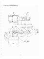
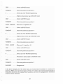
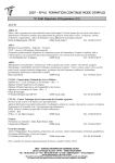
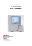
3. Dimensions and Axis Numbers
+
. : . 5~O
+
--=-2..::...0.:::....0-_.IL....-4!_•
1-_2....:....0....:....0
A2 = 200 0
i
I·
300
.,
I
~Al=
I
7
2000
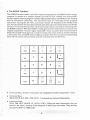
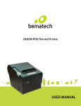
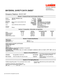
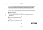
4. The ROB3i Teachbox
The ROB3i Teachbox makes it possihle to operate and program the ROB3i without using a
computer. It consists of a compact keypad unit with 25 keys, divided into three groups:
Numeric keys for entering single or mul tiple-digi t decimal val ues, command keys for en teri ng
directly-executable commands, and instruction keys for entering control program
instructions. To program the robot, you simply connect the Teaehbox to the ROB3i's JlO
port; the uni t can then be easi 1y disco nneeted once the progra m has been started. The female
connector on the Teachhox provides all the inputs and outputs necessary for interfacing with
the ROB3i's I/O port. When the ROB3i is being oper3ted with the Teachbox connected, only
3 digital outputs (DO 1-3) and 5 digital inputs (D1 1-5) are availahle. Each instruction key is
fitted with an LED which lights up to confirm correct entry. If you make an invalid command
or instruction entry, the ERR lamp willligllt up until you clear the incorrect entry by pressing
CLR. All instructions and commands must be confirmed with tbe ENT key.
0
MARK
DEL
0
GOTO
7
0
IF
8
0
0
TIM
OUT
9
l ++
0
INS
4
5
6
0
RUN
STOP
1
0
2
3
0
()
•
ERR
ClR
NOP
pos
t
~
ENT
• Numerical Keys: Used [or entering the a'(is designation numbers and position values.
•
Command Keys:
(RUN, STOP, INS, DEL, POS, alIT) : Commands are executed immediately.
•
Instruction Keys:
(POS, 11M, OUT, MARK, IF, GOTO, NOP) : When you enter instructions, they are
stored in the robot's memory in the sequence in which you enter them. They are on~y
executed in RUN or STEP mode.
8
5. Operating Modes
The robot's integrated control system has six different operating modes:
• INPUT Mode: For creating control programs by entering a sequence of instructions. This
is the default mode which is activated whenever the system is powered up.
• PosmON Mode: This mode isselected by pressing one of the numerical keys 1-6, which
also selects the corresponding axis. You can then move the (L'(is forwarus or backwards
with the + and - keys. In this mode, you ,can also position the axes directly with the
sequence POS (axis a). (posi'tion n) ENT. Pressing CLR returns you to the INPUT mode.
• RUN Mode: When you enter RUN (label m) ENT, ROB3i starts executing the sequence
of instructions in its memory starting at label ill.
• BREAK Mode: When the robot is in RUN mode, all keys except the STOP key are
disabled. Pressi ng STO P CLR activates the BREAK mode. You ca n swi teh back to RUN
mode with RUN ENT (= CONTINUE). Pressing STOP ENT allows you to select any of
the other modes.
---,
• STEP Mode: Entering RUN. (label m) ENT switches on the STEP mode, starting at
label m (provided that label m exists, of course). You can then run through the program
one step at a time by pressing the + key. Pressing CLR exits the STEP mode.
• DISPLAY Mode: Entering STOP. (label m) ENTswitches the system to the DISPLAY
mode, starting at label m. When you p'ress the + key, the next instruction stored in the
sequence in memory is displayed (the corresponding LED on the Teachhox lights up),
but the instruction is not executed on the ROB3i. Pressing CLR exits the DISPLAY
mode.
9
6. Summary of all Instructions and Commands
Instructions:
MARK m ENT .. Set label m . . . . . . . . . .
· m=O.. 1l8
pas ENT
Store current position
TIM t ENT
Set delay period t (x lOOms)
· t = 1.. 65535
GOTO m ENT .. Go to label m . . . . .
· (endless loop)
GOTO m. n ENT . Go to label m, n times . . .
. . n =0..255
IF i ENT ..
. Wait until input i = low
IF i. m ENT . . . . If input i = low go to label m
. . . . . . . . . . . . else continue with next instruction
k +/- ENT .. Set/clear digital output k
k = 1..8
. ENT . . . .
. NOP instruction
STOP 0 ENT
. Program start
INS. ENT .
. Program end
DEL. ENT
. Halt instruction, used to separate two consecutive programs in memory
our
Commands:
a +/~ ENT
POS a . n ENT
Move axtS a in POSITION mode
Move axis a to position n
a = 1..6
o lIT . k + /- ENT . Set/clear digital output k directly
RUN m ENT
Run from label m
RUN. m ENT
Activate STEP mode starting at label m
RUN ENT
Continue (BREAK mode)
RUN. ENT
Continue (STEP mode)
STOP CLR
Break, stop program execution, continue with RUN ENT
STOP ENT
Stop, switch to INPUT mode
STOP. ENT .,. Activate DISPLAY mode
STOP .m ENT
Activate DISPLAY mode starting at label m
INS ENT
Insert inc:,truction
DEL ENT
Delete instruction
CLR . . . . . . . . . Change mode, clear on error
Special features of the pneumatic gripper:
6 +/-ENT
Pressing the PLUS or MINUS key once moves the gripper to the opposite end position.
POS6. nENT
An even value for n opens the gripper, an odd value closes it.
10
7. Reference to the Individual Instructions
• Program Start
STOP 0 ENT
This sequence generates the progr<lJn header, cle~lring the contents of the ROB3i's memory
and initializing it for programming. It shou ld only be entered once, nt the beginning of a new
programming session. DON'T use this comm<lnd when you want to edit programs already in
memory or add new programs to the those in memory, as it will completely erase all the
instructions and programs already stored in the memory!
MARK O:ENT
. Set label 0, marks beginning of the program.
CLR , . . . . ..
. Switch to input mode.
This is followed by the body of the program, consisting of positioning sequences, loops and
input and output instructions.
• Axis Positioning
(Axis a) +/
Using this command, you can move (L'{is a IIp/right 'Or left/down with the + /- keys until it is
in the desired position. Since the control program can posi,tion several axes nt the some ti me,
you can position any number of axes using tbis technique, l\11~i1 the robot mm is in the desired
positi,on.
CLR ..
· Switch to INPUT mode.
POS ENT
· Store arm position in memory
or:
POS (axis a) . (position n) ENT
Moves axis a directly to position n. Again, you can position any number of axes in this way,
until the arm is in the desired position.
CLR . . .
· Switch to INPUT mode
POS ENT
· Store arm position in memory
• Loops
MARK m ENT
.. Set label In as loop starting point
Create the body of the loop by teaching in the arm positioning sequences (see above).
GOTO ill ENT ... Loop to the starting point label (for endless loops). This opti.on is useful
11
for writing endlessly repeating programs. You can terminate these programs with the
STOP function.
GOTO m . n ENT . Loop to starting point label n times, thus repeating the instructions in
the body of the loop n times. For i = 1 to n loop repetitions.
• IJO Instructions
IFi ENT
. Stop execution at this point in the program until input i is low.
IF i . m ENT
. If input i is low when the state men t is execu ted, a jump is performe d to
label m; otheIViise, execution continues with the next instruction.
OUT k + j- ENT .. Set/clear output k
Please note the negative TTL logic!
Set = low, clear = high.
OUT. k +/- CLR . Allows you to poll the I/O port and the ROB3i periphery directly,
either during a programming session or during a brenk in program execution. Please don't
terminate this command with ENT, as this will store it in memory as part of the control
program.
•
Set Delay
11M tENT
A lIows you to in terru pt program execu ti on for a specified pe riod (t x 100 ms). The range of
t is from ato 65535, which means that you can program delays of up to 100 minutes. Insert
the instruction in a loop to program longer delays.
• Program Halt
DEL.ENT
Generates a program halt, and switches on the RUN lamp. Execution can be restafted by
pressing ENT. This instruction is also used as a separator between consecutive, separate
programs in memory. Pressing CLR switches to INPUT mode.
• Program End
INS .ENT
This sequence must always be entered at the end of every teach-in program. When you are
editing existing programs, it should never be entered if you make changes in the body of the
program on fy, bu t you MUST en ter j t if you le ngt he 11 th e progra m by overwri ti ng the origi nal
program end instruction (see Appending lnstructions below).
12
•
DISPLAY Mode
STOP. m ENT / STOP. ENT
These commands switch the system to DISPLAY mode, allowing you to display the program
instructions stored in memory one after another via the LEOs, by pressing the + and - keys
to step forwards and backwards through the program. The MARK. POS, TIM, OUT, IF and
NOP instructions are displayed directly with the LEOs of the corresponding keys; the DEL
. instruction is displayed with the MARK and Nap LEOs together. The ERR LED lights up
in the event of errors and at the end of the program (program end instruction). Pressing the
CLR key exits the DISPLAY mode.
• Insert Instruction
INS ENT
The DISPLAY mode makes it simple to move to the position where yOll want to insert one
or more additional iI1structi ons. To insert ios t ru cti () ns, proceed as follows: Firs I, swi teh to
DISPLAY mode and locate the instruction BEFORE which you want to insert the new
instruction(s). Press CLR to exit the DISPLA Y mode. and then press INS ENT once for each
instruction you wish to insert. This inserts NOPs, which you can later overwrite with the
appropriate instructions.
•
Delete Instruction
DELENT
In the same way as for inserting instructions, first switch to DISPLAY mode and locate the
position at you wish to begin deleting, then press CLR to exit DISPLAY. Now press DEL
ENT once for each instruction to be deleted. Each time you press DEL ENT, the current
instruction is cleared from memory and all the following instructions are moved up by one
line, allowjng you to go on deleting towards the end of the program.
• Appending Instructions
Existing programs can be lengthened very easily by overwriting tbe program end instruction.
First, switch to DISPLAY mode and locate the end of the program. The ERR LED will light
up. Now press CLR to switch to INPUT mode, and simply enter the additional instructions
normally. Don't forget to enter the INS. ENT sequence again when you are finished!
•
Overwriting Instructions
This function is used to overwrite previously-entered NOPs, existing instructions or Naps
entered directly with the INS ENT sequence. Switch to DISPLAY mode and locate the
instruction you wish to overwrite, then press the CLR key and enter the new instructions
directly.
--
13
•
Program Run / Break
You can choose between running the program normally or in single-step mode.
RUNmENT
· Start normal program execution at label m
STOPCLR
· Break program execution at any point
RUNENT
· Resume program execution at point where it was interrupted
The instruction sequence RUN. m ENT selects single-step mode, allowing you to test the
program by running it one instruction at a time. You can then step through the program with
the + key. Each time you press +, the next instruction in the memory is executed, moving
the robot axes and lighting up the corresponding LED on the Teachbox.
14
8.Hardware Installation
The robot can be fitted with either an electrical or a pneumatic gripper, making it possihle
to perfonn an extremely wide range of different handling tasks. The integrated control system
automatically identifies the gripper type and controls it accordingly.
Installing the electrical gripper is a simple mechanical operation. Proceed as follows:
• Snap the electrical gripper onto the gripper mounting flange in the position you wish to
define as the center position.
• Insert the gripper plug into the matching socket and screw it into place. Arrange the spiral
cable so that it will not obstruct the gripper.
• The ROB 3i is then ready for operation with the electric31 gripper.
To install the pneumatic gripper, proceed as follows:
• Snap the pneumatic gripper onto the gripper mounting flange in the position you wish to
define as the center position.
• Coil the black and blue hoses loosely around the gripper's rotary axis, then connect them
to the gripper. Connect the blue hose to the connection which is closest to the gripper
fingers.
• Insert the plug attached to the red and black cable into the matching socket and screw it
into place.
• Mount the pressure reducing valve on the base of the robot, using two screws. Connect
the blue compressed air hose from the base of the robot to the pressure reducing valve.
• Snap the FESTO PU3 compressed air hose onto the FESTO CN-M5-PK3 connector
nipple (max. operating pressure 6 bar / 60{)() hPa). The pressure reducing valve is set for
a gripper operating pressure of 5 bar 15000 hPa.
• The ROB 3i is then ready for operation with the pneumatic gripper.
Hardware requirements:
-
The ROB3i
The power supply unit
The Teachbox
The RS-232 shorting connector
Connect the ROB3i to the power supply unit with the two power leads. Plug the Teachbox's
25-pin male connector into the 110 port and the 9-pin shorting connector into the RS-232
port. Turn the power switch to ON, and press the RESET key on the ROB3i. Now you can
enter a program or move the ROB3i's arm directly with the appropriate instructions.
The ROB3i's program memory is nonvolatile, and is powered by a long-life lithium battery;
your programs will remain stored in the robot's memory for around 10 years, even when the
mains power is switched off.
15
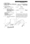
9. Digital Inputs and Outputs, EMERGENCY OFF Function
• Digital Inputs (TTL)
DI1:
DI2:
DB:
014:
DIS:
10K
Pin 19
Pin 6
DI6:
Pin 18
017:
Pin 5
Pin 17
DI8:
y+sv
Pin 8
Pin 20
Pin 7
1
-DI
n..
~
100K
4069
1
All the digital inputs are active LOW
• Digital Outputs (TTL)
001:
Pin 25
D02:
Pin 12
003:
Pin 24
D04:
Pin 11
D05:
Pin 23
IJrI
D06: Pin 10
D07:
Pin 22
DOB:
Pjn
74LS244
0
~o
9
All the digital outputs are active LOW
• EMERGENCY OFF for the ROB3i
DIlO: Pin 4
The EMERGENCY OFF input is active LOW
The emergency off function is realized with an NOe across pins 4 and 1 of the robot's I/O
port. Activation of the function switches off the ROB3i's motors. After eliminating the
problem, you must execute a RESET on the ROB3i unit, then you can restart the control
program.
16
•
Power Supply
Gnd:
Pin 1
+ 5V Pins 2/13
1<= SOmA
The power supply unit is only suitable for the connection of optocQuplers. Any external driver
stages must be provided with their own power supply. Please note that the ground lines should
NOT be cormected when optocouplers are being used.
10. Exercises with the Teachbox
Connect the ROB3i and switch it on as described in Section 8, H3rdware Installation. Before
you begin the exercises, we suggest that you first move the robot's arm to the following home
position:
Axis
1
2
.255
3
.255
4
.255
.255
5
6
. Position
.255
. 0 (electric or pneu matic gripper is open)
To position the first axis, enter the following key sequence: POS 1 (decimal point). ENT.
When you press ENT, axis 1 of the ROB3i will immediately move into position 255, which
is the central position. Repeat the procedure with the appropriate values for the remaining
five axes.
CAUTION:
Please be extremely careful when you position axes 2 and 3 directly, as these axes can move
the gripper below the plane oUhe surface on which the ROB3i is mounted, which can result
in gripper damage. Positions 0..30 and 225..255 with axis 2 are particularly dangerous. If
the gripper ever does collide the tabletop when you are positioning the arm directly, press
the STOP key on the Teachbox immediately and hold it down until you have pressed the
RESET key on the ROB3i. This initializes the last arm position as the current position. The
ROD3i will then stop in this position, and you can change the position by entering further
teach Instructions. Please note that a reset clears all program instructions entered
beforehand from the robot's memory, and they must then be reentered from the start,
17
If the red ERR lamp on the Teachbox lights up while you are entering instructions, first clear
the error condition by pressing the CLR key, then reenter the last instruction sequence.
All the following exercises are entered with label 0 as the starting address, and can he started
by en tering RUN 0 ENT. If you wish, however, you can <llso en ter at her starting add resses,
so long as they are within the permitted value range (0 < = starting address < = 118).
• Program Header and Program End
STOP 0 ENT
This sequence generates the program header, clearing the contents of the ROB3i's memory
and initializing it for programming. It should only be entered once, at the beginning of a new
programming session. DON'T use this command when you want to edit programs already in
memory or add new programs to the those in memory, as it will completely erase all the
instructions and programs already stored in the robot's memory!
MARK 0 ENT
. Set label 0 as the starting address, marking the beginning of your program.
CLR . . . . . ..
. Switch to POSITION mode
This is followed by the body of the program, consisting of positioning sequences, loops and
input and output instructions.
INS. ENT
This sequence must always be entered at the end of every taught-in program. When you are
editing existing programs, it should never be entered if you make changes in the body of the
program only, but you MUST enter it if you lengthen the program by overwriting the original
program end instruction and adding more instructions.
• Practice Programs
PROGRAM 1: Single Axis Positioning
STOPOENT .
· Clear memory, generate program header
MARKOENT
· Enter start address
CLR . . .
· Switch to INPUT moue
POSENT
· Store home arm position as starting position
(All the practice programs begin with these four lines)
1 .
· Select axis 1 for TEACH positioning
+
· Depress key to turn right in TEACH mode
18
CLR ...
· Switch to INPUT mode
POSENT
· Store new position as position 2
1 .....
· Select axis 1 for TEACH positioning
· Depress key to turn left in TEACH mode
CLR . .
. Switch to INPUT mode
POS ENT
. Store new position as position 3
POS 1 . 400 ENT
_Move a.xis 1 to position 150
CLR . . .
. Switch to INPUT mode
POS ENT
. Store new position as position 4
POS 1 .50 ENT
. Move axis 1 to position 50
CLR . . .
. Switch to INPUT mode
POS ENT
. Store new position as position 5
INS. ENT
. Program end
This program uses two different methods for entering single axis movements: Direct
teaching, using the + and - keys, and direct entry of the target position with the POS (axis
a) . (position n) ENT instruction sequence. Both of these methods can be used for all the
robot's axes.
PROGRAM 2: Consecutive Single Axis Positioning for all 6 Axes
STOPOENT .
· Clear memory, generate program header
MARKOENT
· Enter start address
CLR . . . .
· Switch to INPUT mode
POSENT .
· Store home arm position as starting position
(Standard beginning of the program)
POS 1 .400 ENT .. Move axis 1 to position 150
19
CLR .. ,
· Switch to INPUT mode
POSENT
· Store new position as position 2
2 .....
· Select axis 2 for TEACH positioning
· Depress key to move up in TEACH mode
CLR ...
· Switch to INPUT mode
POSENT
.. Store new position as position 3
POS 3 . 180 ENT
- Move axis 3 to position 50
CLR . . .
· Switch to INPUT mode
POSENT
· Store new position as position 4
4
· Select axis 4 for TEACH positioning
· Depress key to move up in TEACH mode
CLR ..
· Switch to INPUT mode
POSENT
· Store new position as position 5
POSS .1OENT
· Move axis 5 to position 10
CLR
· Switch to INPUT mode
.
POSENT
· Store new position as position 6
6
· Select axis 6 for TEACH positioning
· Press key to open gripper in TEACH mode
CLR
· Switch to INPUT mode
POSENT
· Store new position as position 7
INS.ENT
. . . Program end
In the above example, all of the robot's axes are moved one after another in a consecutive
sequence. When you start the program, all the axes will first be moved simultaneously to
bring them back into the original home position, and then the programmed movement
sequence will be repeated.
20
PROGRAM 3: Simultaneous Multiple Axis Positioning
Note: No matter how many axes you move, the new robot arm position is not stored in the
memory until you enter the POS ENT sequence.
STOPOENT .
· Clear memory, generate program header
MARKOENT
· Enter start address
CLR ...
· Swi tch to lL'1PUT mode
POSENT
· Store home arm position as starting position
(Standard beginning of the program)
POS 1 . 400 ENT . . Move axis 1 to position 150
2
· Select axis 2 for TEACH positioning
.. Press key to move up in teach mode
CLR
· Switch to INPUT mode
POS 3 . 180 ENT . . Move axis 3 to position 50
4
· Select axis 4 for TEACH positioning
· Press key to move up in TEACH mode
5
· Select axis 5 for TEACH positioning
· Press key to turn right in TEACH mode
6
· Select axis 6 for TEACH positioning
· Press key to open gripper in TEACH mode
CLR
· Sv..ritch to INPUT mode
POSENT
· Store new position as target position
INS.ENT
· Program end
Now that you have familiarized yourself with beginning and terminating programs and
positioning single and multiple axes, you can stan adding other instructions to your programs.
Please consult Sections 6 (Summary of all Instructions and Commands) and 7 (Reference to
the Individual Instructions) for full details.
21
PROGRAM 4: Sample Program
STOP 0 ENT . . . . Clear memory, generate program header
MARK 0 ENT . . . Enter start address
eLR ...
.. Switch to INPUT mode
POS ENT
Store home arm position as starting position
(Standard beginning of the program)
TIM 40 ENT . . . . Set delay, 4 seconds
POS 1.400 ENT .. move axis 1 to position 150
CLR . . . . . . . . . Switch to INPUT mode
POS ENT
Store new position as position 2
IF 1 ENT
· Wait until input 1 is set (LOW = gnd)
2 .....
· Select axis 2 for TEACH positioning
• .
Press key to move up in TEACH mode
CLR
Switch to INPUT mode
POS 3 . 180 ENT .. Move axis 3 to position 50
4
.
· Select axis 4 for TEACH positioning
. . Press key to move up in TEACH mode
CLR
· Switch to INPUT mode
POS ENT ...
· Store new position as position 3
TIM 20 ENT . . . . Set delay, 2 seconds
(The following sequence switches another machine or device on, leaves it on for 10
seconds then switches it off again.)
OUT 1
+ ENT .. Set output 1 to LOW
TIM 100 ENT
= gnd
... Set delay, 10 seconds
22
OUT 1 - ENT
. Reset output 1 to HIGH = + 5V
GOTO 0 . 5 ENT
. Loop to label 0 5 times
INS . ENT
. Program end
Tips and Suggestions:
- You should also set a delay of 1/2 second before gripping or releasing something with the
gripper. This gives the gripper time to come to rest, ensuring ilia t the object will be gripped
and released smoothly and cleanly.
- We strongly advise that you first test your programs in single-step mode after teaching
them in. Stan the program with RUN .0 ENT; you can then step through the program one
instruction at a time with the + key. All the instructions (MARK POS, TIM etc.) will be
displayed on the LEDs of the Teachbox as they are executed, starting \\Tith the first MARK
instruction and ending with the program end instruction (the latter is indicated by the ERR
LED). At the same time, the robot will· execute the pro.grammed movements.
11. Limited Warranty Tenus and Conditions
Warranted against defects in materials and workmanship for a period of 6 (six) months as of
the date of purchase, delivery free works. Wearing parts such as motors and potentiometers
are excluded from this Warranty coverage. The use of physical force, incorrect connection
and any and all alterations or repair attempts on the part of the Customer will render this
Warranty null and void.
We reserve the right to make technical alterations without notice.
Shipping address for service and repair:
p + P Elektronik GmbH
Nordring 23, 8510 Furth 2, West Germany, Tel. 0911 - 3000-611, FAX 0911 - 3000-622
23
12. Foreign Distributors
Fa. Patech
Peter Schibli
Heidenhubelstr. 13
CH - 4503 Solothurn
Tel. 065/23 3824
Fax: 065/221523
Hilrobte<:
Hr. Hilti
Postfach 353
9490 VaduzILiechtenstein
Tel. 075/29475
Fax: 075/23132
Bie & Berntsen Ltd
Torben Ingemann Andersen
Sandbaekvej 7
DK - 2610 Rodovre
Tel. 02948822
Fax: 02942709
Del - Rain Europe
Heereweg 441B
P.O. Box 280
NL - 2160 AG Lisse / Niederlande
Tel. 0 25 22 - 1 7433
Fax: 02523 - 3 11 01
Soria
M. Martes
39 bis. Rue du General Leclerc
F - 92270 Bois - Colombes
Tel. 1/478169 10
Fax: 1/ 45 63 81 02
TS Tecno Service sri
Fernando Sobacchi
Via Europa. 9
I - 20085 Locate Triulzj (Mi!<lno)
Tel. 02/90730332
Fax: 02/90797 13
Micro-Nord
Dr. lng. Lv.Ferrari
Via Segantini, 18
1- 39100 Bolzano Iltalien
Tel. 04 71/280144
Fax: 04 71 /282745
TEX
Erich H. v. Ruffer
20 Shawnee Drive
USA - Watchung N. J. 07060
Tel. 201 /754 65 50
Fax: 201 /75494 14
GT Produetique SA.
Mr. Antoine Mucciante
Immeuble Agora - Z.I. Dom~ne
F - 38420 Domene
Tel. 76 77 1980
Fax: 76 77 18 55
24