1
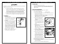
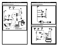
Quickie S-525
Integrated C.G.Tilt
User
Instruction
Manual
Supplement
SUPPLIER:
THIS MANUAL MUST BE GIVEN TO THE
RIDER OF THIS WHEELCHAIR.
RIDER:
BEFORE USING THIS WHEELCHAIR
READ THIS ENTIRE MANUAL AND SAVE
FOR FUTURE REFERENCE.
1 .
I N T R O D U C T I O N
N O T E
QUICKIE S-525 INTEGRATED C.G. TILT
USER INSTRUCTION MANUAL SUPPLEMENT
1 1 .
TA B L E
O F
C O N T E N T S
1. INTRODUCTION NOTE........................................................................2
11. TABLE OF CONTENTS..........................................................................3
NOTE:This supplement contains information on the operation and adjustments
for the Integrated C.G.Tilt System of a Quickie S-525 wheelchair ONLY. Please
refer to the Quickie S-525 User Instruction Manual for additional notices, EMI
information, warnings, tips for attendants, set-up, adjustment and use information,
operating guide, battery and maintenance information, wiring diagrams, and warranty information regarding the Quickie S-525.
SUNRISE MEDICAL
Customer Service Department
7477 East Dry Creek Parkway
Longmont, Colorado 80503
(303) 218-4500 or (800) 333-4000
111. YOUR CHAIR AND ITS PARTS ..........................................................4
IV. WARNINGS....................................................................................................6
A. Solid Seat Back
B. Driving
C. Tilting
V. SET UP, ADJUSTMENT & USE............................................................7
A. Battery Removal....................................................................................7
B. Solid Seat Back & Lateral Thoracic Supports ........................7
C. Headrest ....................................................................................................8
D. Foam Back ................................................................................................9
E. Seat Tilt Adjustments ..........................................................................9
F. TM40 Single or Dual Switch Actuator Controller ............10
G. Check Out ..............................................................................................11
VI. OPERATING GUIDE ..............................................................................12
A. Toggle Switch Activation
B. Single Switch Activation
C. Integral Joystick Activation
D. Remote Joystick Activation
VII. MAINTENANCE & TROUBLESHOOTING TIPS......................13
A. Maintenance
B. Troubleshooting Tips
VIII. WIRING DIAGRAMS ............................................................................14
IX. SUNRISE LIMITED WARRANTY ....................................................15
931156 Rev. A
2
3
931156 Rev. A
1 1 1 .
Y O U R
C H A I R
A N D
I T S
1 1 1 .
P A R T S
Y O U R
C H A I R
A N D
I T S
P A R T S
QUICKIE S-525 INTEGRATED C.G.TILT
5
3
4
6
2
9
8
12
7
1
10
13
14
Q U I C K I E
15
S - 5 2 5
11
I N T E G R AT E D
10. Battery Box
11. 12” Drive Wheels
12. Swing-Away Quick Release
Footrest Lever
13. Caster Housing
14. 8” Solid Casters
15. Caster Fork
16. Tilt Toggle Switch (not shown)
17. Headrest (not shown)
1. Push Handle
2. Dual Post, Height-Adjustable
Armrest
3. Remote Joystick (optional)
4. Jay Cushion (optional)
5. Swing-Away Footrest Latch Plate
6. Swing-Away Footrest Hanger
7. Heel Loop
8. Composite Footplate
9. Solid Seat Back
931156 Rev. A
C . G . T I L T
4
Backrest
Standard - Non-folding: 15" - 20"
Option - Folding: 15" - 20"
Straight Backpost - standard
Footrest
Standard - Swing-away with composite footplates and heel loops.
Option - elevating legrests, multipositional and angle-adjustable footplate
Casters
Standard - 8" solid
Option - 8" airless insert, 8" pneumatic
Armrests
Standard - dual post flip back
Option - height-adjustable dual post
or single post with desk or full
length waterfall pads
Wheel Locks
Option - Push-to-lock
Option - 6" extension handles
Drives
Right-angle Helix Drive System
Swing-Away Lateral Thoracic Supports
Option - Curved
Option - Straight
Headrest
Standard - 9” x 5” headrest pad
Weight
145 lb.With swing-away footrests
and armrests, without batteries
Drive Wheels
12" Mag
Tire types:
Standard - pneumatic
Option - airless insert, solid
Joystick
Standard - integral (right-hand or
left-hand mount)
Optional - remote (right-hand or
left-hand mount)
Option - swing-away retractable
joystick (remote only)
Batteries
(2 batteries required to operate chair)
Option - 22 NF deep cycle gel,
Option - U1 deep cycle gel
Battery Charger
Standard - off board (Lester)
Colors
Refer to current order form
Chair Parts
Standard - black
Seat Frame Dimensions
Seat Frame width: standard - 14"-20"
Seat depth: 14"-18" adjustable
Solid seat back
Aluminum seat pan
Optional cushions: Jay Cushions
CG Tilt
3° - 50°
6° - 50°
All features may not be available with
some chair setups or in conjunction
with another chair feature. Please
consult your supplier for more
information.Your authorized supplier
can also provide you with more
information on accessories.
5
931156 Rev. A
1 V.
! W A
▲
R N I N G S
A. SOLID SEAT BACK
Do not use the Solid Seat back to push or lift the wheelchair. Improper use may
cause the back to unexpectedly detach from the wheelchair.
V.
S E T- U P,
A D J U S T M E N T
&
U S E
TOOLS YOU WILL NEED
1. Basic Tool Kit:
To set-up, adjust and maintain your chair you will need the following tools:
• 5/32” Allen wrench
• 3/16” Allen wrench
• 5/16” Allen wrench
• 9/16” box and open-end wrench
• Phillips screwdriver #1
B. DRIVING
Always drive your chair when seated at the minimum tilt angle. Driving your chair
when seated at an angle greater than the minimum can cause damage to the tilt
actuator.
C. TILTING
To prevent damage and personal injury, avoid tilting near objects such as walls,
tables or chairs.
To avoid injury, ensure other people, especially children, are clear of the system.
D. CHANGES & ADJUSTMENTS
Never use non-Quickie parts or make changes to your chair unless authorized by
Sunrise. (Doing so will void the warranty and may create a safety hazard.)
1. If you modify or adjust this chair it may increase the risk of fall or tip-over.
2. Modifications unauthorized by Sunrise constitutes remanufacturing of the
wheelchair. This voids the warranty. The rider then assumes all future
liability for the wheelchair.
NOTE: Setting the wheelchair on a flat surface, such as a table or a workbench, helps
make these procedures easier.
A. BATTERY REMOVAL
To remove the batteries for transporting or
servicing:
1. Remove Battery Box
a) Turn both swedge latches up (fig1&2,A)
located on the rear of the battery box.
b) Slide the box lid rearward until it is
removed.
c) Disconnect Power harness (fig 3, C), by
pulling plug rearward.
d) Grab handle (fig1, B)and pull entire batter box away from chair.
e) Disconnect each battery and remove
from batterybox as needed.
2. Battery Installation
See section XI. Batteries, D for instructions
and wiring diagram.
A
A
C
Batteries may weigh up to 40 lbs. Care
must be taken to avoid injury when lifting.
B. SOLID SEAT BACK & LATERAL THORACIC SUPPORTS
1. To adjust the height of the lateral support mount, loosen the adjustment
screw until the receiver slides freely on the back posts.Tighten the adjustment screw when the proper height is determined.
2. Assess and fit the lateral thoracic supports. Assess client for proper positioning of the lateral thoracic supports. Each support is independent and
may be adjusted for your client’s clinical need.
931156 Rev. A
6
7
931156 Rev. A
V.
S E T- U P,
A D J U S T M E N T
&
U S E
V.
A minimum of 1” (2.5 cm) of clearance should exist between the top of the lateral support and the user’s arm pit.
a) To adjust the height, angle, or width of the lateral thoracic support
pads, loosen the top bolts and slide to correct width.Tighten bolt to
bolt plate. If more adjustment is necessary, loosen the internally mounted bolts, and slide in the track to the desired height and width.The
angle is obtained by tilting the bracket as needed.Tighten the bolts.
b) To adjust the depth of the lateral thoracic pads, turn the middle bracket so
that the slots are on side.Adjust to desired depth. Re-tighten the bolts.
C. HEADREST
1. Mounting a headrest.
The Solid Seat Back has a headrest plate
mounted to it. Care should be taken to
use the proper screw length when
mounting.
2. To position the headrest use the double
clamp and the collar clamp (B,C,D) to
obtain the proper height and distance.
For clamp B use a 3/32 Allen set screw
(A) and a 3/16 Allen cap screw. Clamp B
positions the headrest forward and aft.
However, due to the vertical movement
of this adjustment, collar clamp D will
have to be moved in conjunction.
3. Retighten both the 3/16 Allen and the set
screws (A) with a 3/32 Allen wrench.
931156 Rev. A
8
A
B
B
D
C
A
S E T- U P,
A D J U S T M E N T
&
U S E
D. FOAM BACK
1. Secure the foam and cover to the shell.
To secure the back foam and cover on the Solid Seat Back, slide the top
edge of the cover over the top lip of the shell. Press the back in place
against the shell.
E. SEAT TILT ADJUSTMENTS
The minimum and maximum seat tilt angles can be adjusted.
1. Lower Stop Limit Adjustment
a) Seat must be in full upright
(untilted) position.
b) Use the 5/16” Allen wrench to loosen the socket head cap screws on
both sides of the chair. (A)
c) Use the 9/16” open-end wrench to rotate the lower arm pivot (B)
until the front of the seat is as high as possible.
Note: Will tilt back only a small distance.
d) Use the 5/16” Allen wrench to
tighten the socket head cap
A
screws (A) and secure the lower
arm pivot.
e) Use the 3/16” Allen wrench and
B
1/2” open-end wrench to remove
bolts (C) holding the lower stop
blocks.
f) Reposition lower stop block to the
desired holes. (D)
Note: Lower stop limit tilt angle:
upper position = 6 degrees; lower
position = 3 degrees.
g) Use the 5/16” Allen wrench to
loosen the socket head cap screws
(A) on both sides of the chair.
h) Use the 1/2” open-end wrench to
rotate the lower arm pivot until
the upper stop blocks just come to
D
rest on the lower stop blocks.
i) Use the 5/16” Allen wrench to
C
tighten the socket head cap screws
(A) on both sides of the chair.
j) Verify that the desired lower stop limit has been achieved.
2. Maximum Tilt Angle Limit Adjustment
a) Use the #1 Phillips screwdriver to loosen the two screws (A) holding
the front limit switch.
b) Slide the front limit switch (B) completely forward.
9
931156 Rev. A
V.
S E T- U P,
A D J U S T M E N T
&
U S E
V.
S E T- U P,
c) Tilt the seat to the desired limit.
d) Slide the switch (B) back toward the rear until it comes into contact
with the tilt carriage.
Note: Sliding the switch (B) toward the back of the chair decreases
the tilt limit angle. Sliding the switch (B) toward the front of the chair
increases the tilt limit angle.
Note: A soft, audible click can be heard as the switch arm (B) comes
in contact with the carriage.
e) Use the #1 Phillips screwderiver to tighten the switch to the point
where the switch closes.
Note: Listen for the soft, audible click.
f) Verify that the desired tilt angle has been achieved.
Note: Maximum tilt angle is adjustable to 50°.
A D J U S T M E N T
&
U S E
I
E
A
Stereo
Jack
B
F
Stereo Jack
D
Mono Jack
C
H
J
G
B
A
F. TM40 SINGLE OR DUAL SWITCH ACTUATOR CONTROLLER
The TM40 actuator controller can be used to activate the tilt mechanism with
either single or dual switch controls.
1, Plug limit switch harness assembly (A) into TM40 limit switch jack (B).
2. Plug single switch (C) into TM40 single switch jack (D) OR plug dual switch
(E) into TM40 dual switch jack (F).
3. Plug TM40 into the QTRONIX Power Module (G) or the Pilot Controller
Communications Connector ( J).
4. Use mating plugs (H) to connect the TM40 to the tilt actuator.
931156 Rev. A
10
G. CHECK-OUT
Once the tilt assembly is adjusted, it should
actuate smoothly and easily. All accessories
should also perform smoothly.
1. Verify seat can achieve full tilt and will
return to neutral.
2. Verify upper and lower stop blocks
meet (A).
3. Verify the motor cuts out once the neutral position is reached.
4. Verify no debris is interfering with the
glide bearings.
5. Verify all hardware is securely tightened.
6. Verify that the tilt lock-out sensor ( I ) is
positioned in its mount with its wires
leading out toward the front of the chair.
11
A
931156 Rev. A
V I .
O P E R AT I N G
V I I .
G U I D E
A
NOTE: Check weekly, and use a clean, dry cloth or compressed air as needed
to keep glide bearings free of debris.
ly
ly
rly
al
te
nu
ar
An
Qu
th
Check tires for proper inflation level
✓
Check batteries for proper electrolyte level (wet cell only)
✓
✓
Check all moving parts for wear
✓
Inspect all nuts, bolts and fasteners for looseness or wear
✓
Inspect upholstery for wear
✓
Remove and inspect motor brushes
✓
✓
Servicing by authorized Supplier
B
on
✓
Check plugs and connectors for proper connections
C
y
12
Glide bearings free of debris
D
C
kl
B
M
931156 Rev. A
✓
Charge Batteries
D. REMOTE JOYSTICK ACTIVATION
(OPTIONAL)
From the “off” position
1. Push the on/off mode select toggle
switch (A) down once to turn the chair
“on”.
2. Push the on/off mode select toggle
switch (A) up twice to move index to
tilt mode (noted by two (2) actuator
lights (B)).
3. Push the joystick (C) forward to tilt
backward or backward to tilt forward.
4. Push the on/off mode select toggle switch
(A) up once to return to drive mode.
ily
CHECK...
A
ee
W
Da
B. SINGLE SWITCH ACTIVATION
1. Depress and hold single switch to tilt
back into the desired position.
2. Depress and hold single switch to
return to neutral until tilted into the
desired position.
C. INTEGRAL JOYSTICK
ACTIVATION (OPTIONAL)
From the “off” position:
1. Push the on/off button (A) once to turn
the chair on.
2. Push either tilt button (B or C) to activate tilt mode.
3. Push forward on joystick (D) to tilt
back.
4. Pull backward on joystick (D) to tilt forward.
5. Push either tilt button (B or C) to deactivate and resume drive mode.
T I P S
A. MAINTENANCE
You should check the items on this chart at the indicated intervals. If any of the
items are loose, worn, bent or distorted, immediately have them checked and/or
repaired by your authorized Sunrise supplier. Frequent maintenance
and servicing will improve performance and extend wheelchair life.
TO OPERATE THE C.G. TILT
A. TOGGLE SWITCH ACTIVATION
1. To operate, push the toggle switch (A)
forward (to tilt back) or pull toggle
backward (to return to neutral) until
tilted into the desired position.
2. The toggle switch will return to neutral
when released and the seating system
will stop moving.
M A I N T E N A N C E & T RO U B L E S H O OT I N G
B. TROUBLESHOOTING TIPS
If you should notice your C.G.Tilt system binding up, not running in a smooth
fashion, or emitting an unusual noise during use, a foreign matter may have come
into contact with the glide bearings. If this occurs, use a clean, dry cloth or compressed air to clear or, if needed, please see your authorized Sunrise supplier.
If your tilt system will not function, check to ensure the tilt lock out sensor is
seated properly in its mount.The wires should lead out of the sensor toward the
front of the chair.
A
13
931156 Rev. A
V I I I .
W I R I N G
D I A G R A M S
V I I I .
W I R I N G
TM40 ACTUATOR CONTROLLER
ALM ACTUATOR CONTROLLER
(Independent switch control, Integral Joystick, and Remote Joystick)
(Through drive control– Integral Joystick)
D I A G R A M S
ALM ACTUATOR CONTROLLER
(Through drive control– Remote Joystick)
931156 Rev. A
14
15
931156 Rev. A
I X .
S U N R I S E
L I M I T E D
W A R R A N T Y
FOR THREE (3) YEARS:
We warrant the C.G. power tilt seating system seat frame, sub-base frame, actuator and structural components of this wheelchair against defects in materials and
workmanship for three (3) years from the date of first consumer purchase.
FOR TWO (2) YEARS:
We warrant the ALM (Actuator Lights Module) actuator controller for two (2)
years from the date of first consumer purchase.
FOR ONE (1) YEAR:
We warrant other electronic components such as the single switch actuator controller for one (1) year from the date of the first consumer purchase.
Additional Warranty:
We warrant all other original components (such as upholstery, plastic, rubber
parts and painted surfaces) for three (3) months from the date of first consumer
purchase.
Sunrise Medical
7477 East Dry Creek Parkway • Longmont, Colorado • 80503 USA
(800) 333-4000
In Canada (800) 263-3390
Manufactured under one or more of the following patents:
U.S. and European patents pending.
© 2002, Sunrise Medical 12.02
931156 Rev. A