1
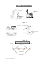
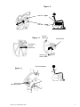
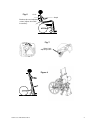
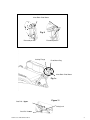
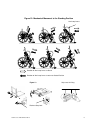
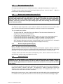
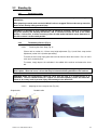
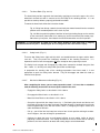
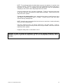
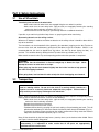
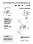
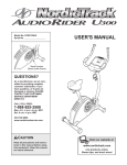
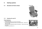
Stand-Up Wheelchair
User’s Manual
the H E L I U M
TABLE OF CONTENTS
PART 1 : OPERATION DIAGRAMS ............................................................................. 2
INTRODUCTION ........................................................................................................... 7
PART 2 : OPERATING INSTRUCTIONS...................................................................... 9
2.1 Positioning - Seated ................................................................................................9
2.1.1 Footplate/lower leg length adjustment (Fig. 1). ....................................................9
2.1.2 Chest strap height adjustment (Fig. 2).................................................................9
2.1.3 Seat frame depth adjustment (Fig. 3). .................................................................9
2.1.4 Anti-tip tubes (Fig. 4). ........................................................................................10
2.1.5 Back angle adjustment (Fig. 5). .........................................................................11
2.1.6 Backrest angle “compensation” system (Fig. 5).................................................11
2.1.7 Backrest height adjustment (Fig. 6). ..................................................................11
2.1.8 Wheel locks (Fig. 7). ..........................................................................................11
2.2 Standing Up ...........................................................................................................12
2.2.1 Preparing to stand. ............................................................................................12
2.2.2 The Standing Process (Fig. 8). ..........................................................................12
PART 3: SAFETY INSTRUCTIONS ............................................................................ 16
3.1
Use of Wheelchair..................................................................................................16
3.2
Transporting ..........................................................................................................16
3.3
Cleaning .................................................................................................................17
3.4
Maintenance...........................................................................................................17
PART 4: TECHNICAL DATA ...................................................................................... 18
4.1
Specifications ........................................................................................................18
Helium User’s Manual March 2010
1
Part 1 : Operation Diagrams
Downpost
Figure - 1
Footrest
Length/Angle
Adjusting
Screws
Figure - 2
Chest Strap
Backrest Tension
Strap
Figure - 2 b.
Chest strap tension adjustment
Left strap
Single buckle
Right strap
Double buckle
Backrest tubes
Helium User’s Manual March 2010
2
Figure - 3
Seat Rail - Upper
Seat Rail - Lower
Anti-tips
Wheels up
Figure - 4
Detent Button
Rear Wheel
Fore-Aft
Adjustment
Anti-tips
Wheels down
Frame Pivot Mount
Figure - 5
-3°
Figure - 6
+12°
2
Back Angle
Adjusting Screws
1
3
Helium User’s Manual March 2010
3
Fig. 6
1 inch
Armpit
Backrest tube and adjusting
screws (adjusts in 0.8 inch
increments)
Fig. 7
Wheel Lock
Adjusting Screw
Figure 8
Helium User’s Manual March 2010
4
Knee Block Pivot Mount
Fig. 9
Retracted position
Locking Flange
Extended position
Pivot Mount Peg
Knee Block Pivot Mount
Fig. 10
Seat Rail – Upper
Figure 11
Safety Lock
Seat Rail - Lower
Helium User’s Manual March 2010
5
Figure 12: Mechanical Movement to the Standing Position
Arm Loop Levers
Rotation of Arm Loop Levers to Stand
Rotation of Arm Loop Levers to return to Seated Position
Grip areas for lifting
Figure 13
B
A
Backrest Stop Lock
Helium User’s Manual March 2010
6
INTRODUCTION
Congratulations on the purchase of your new LifeStand Stand-up Wheelchair by Permobil!
You may have confidence in knowing that you have acquired the best in technology from the worldwide leader
in mobility products.
Before operating your stand-up wheelchair, it is essential to read and carefully follow the below
instructions and operating procedures.
Safety and maintenance:
1) Standing environment
The stand-up feature of this device must only be used on flat, obstacle free surfaces and away from stairs,
ramps, slopes, uneven surfaces or inclines of any kind.
2) Adjustments
Adjustments made to a LifeStand stand-up wheelchair, as described in this document or otherwise, must be
made by an authorized Permobil dealer. Under no circumstance should these adjustments be made by the end
user or non-authorized personnel.
3) Maintenance
It is recommended that you complete a weekly and monthly inspection of your wheelchair.
recommended that it be serviced annually by an authorized Permobil dealer.
It is also
4) Benefits of a Daily Standing Regimen
The use of any stand-up device should be done only under the prescription and supervision of a medical
professional. At the outset, it is recommended that your introduction to regular standing be closely monitored by
your Physical or Occupational Therapist.
It has been documented that the regular and cyclical activity of going from the seated to the standing position
may offer many benefits to those that are no longer able to stand on their own. The benefits are two fold: 1)
there is the ability to once again function in daily activities that necessitate standing (reaching file cabinets and
equipment in the workplace, accessing cupboards/stoves/shelving at home, as well as the ability to interact eye
to eye); and, 2) the potential of physical benefits that result from repeated standing (these benefits may include
improved; range of motion, bone density, circulation, bowel and bladder function, etc.).
Label:
Compliance of this device to annex I of the EU directive 93/42/EEC is
confirmed by this CE label.
Helium User’s Manual March 2010
7
Helium User’s Manual March 2010
8
Part 2 : Operating Instructions
2.1
Positioning - Seated
2.1.1
Footplate/lower leg length adjustment (Fig. 1).
For sitting comfort, and to be properly positioned to obtain a standing posture, the seat to footplate
dimension must be set to the appropriate length. When doing so, it is important that the seat cushion
that client will be using on a regular basis is used.
When setting the lower leg length, the upper leg position should be parallel to the seat rail, but slightly
elevated from the cushion at the front edge. The result is appropriate pressure distribution for the thighs
and buttocks when seated and appropriate hip rotation and extension when standing.
This adjustment is done by removing the Footrest Length/Angle Adjusting Screws located on the lower
part of the downpost. The vertical adjustment is made in .8 of an inch increments. These same screws
are utilized to adjust the footplate angle (to plus or minus 5 degrees).
2.1.2
Chest strap height adjustment (Fig. 2).
To obtain optimum support for the user, especially when standing, the height of the chest strap can be
adjusted. The higher the chest strap is moved up the backrest the greater support it will offer. It is
adjusted by simply releasing its Velcro attachments to the back upholstery and relocating. Make certain
to weave the backrest straps (which are part of the tension adjustable back system) through the metal
retaining rings found on the chest strap.
Please note that additional support straps are available if more support is desired. Please contact
customer service with questions.
2.1.3
Seat depth adjustment (Fig. 3).
2.1.3.1
Measuring.
In seated position, measure the Seat Depth (measured from the front of the backpost to the back of
the knee).
2.1.3.2
Seat depth adjustment (Fig. 3).
Adjust the Upper Seat Rail first, leaving the screws in the Lower Rail (allowing the upper to pivot).
Then, adjust the Lower Seat Rail leaving the screws in the Upper Rail. BOTH THE UPPER AND
THE LOWER MUST BE ADJUSTED EQUALLY.
Utilize the following table to locate the appropriate hole position.
(should be approximately 4cm/1.5” less than upper leg length)
Seat Depth (front of backpost to
BACK of the knee)
Seat Depth-43cm/17"
Seat Depth-45cm/17.5"
Seat Depth-47cm/18.5"
Seat Depth-49cm/19"
Seat Depth-51cm/20"
Seat Depth-53cm/21"
Helium User’s Manual March 2010
Position
Holes Showing (on insert
tube at rear)
0
1
2
3
4
5
0
1
2 std
3
4
5
9
2.1.3.3
Center of Gravity adjustment (Fig. 4)
WARNING! Increasing or decreasing the Seat Depth can relocate the center of mass of the person
in relation to the chair, and therefore the overall system’s Center of Gravity. The end result is that
the chair may become more or less stable depending on if it has become shorter or longer.
After adjusting, it may now be necessary to move the rear wheel mount fore or aft to compensate
for this change.
To make this adjustment, loosen and remove the two rear wheel mount attaching bolts and nuts
(with attached connecting tube) on either side of the wheelchair frame (four bolts total)(See Fig.4).
CAUTION! If the rear wheel mounts and connecting tube are moved forward on the frame, the chair’s
Center of Gravity will move toward the rear, making the front end lighter/easier to tip backward.
If the rear wheel mounts and tube are moved rearward on the frame, the Center of Gravity will move
forward, making the front end more stable.
After the adjustment has been made, replace and retighten the attached bolts and nuts.
WARNING! Any time an adjustment is made to the rear wheel mounts, the balance and operating
characteristics of the wheelchair will be altered. Caution should be taken when the client once again
operates the wheelchair paying special attention to the new balance of the wheelchair.
2.1.4
Anti-tip tubes (Fig. 4).
The anti-tip tubes are mounted to the lower rear of the wheelchair frame. When used properly, they can
prevent the wheelchair from tipping over backward. Use of the anti-tips are recommended at all times.
To put the Anti-tips in operating position, press in the Detent Button (unlocking the tube) and rotate the
tube around so the wheels are in the downmost position. The Detent Button should then again lock the
tube into place.
At times, it may be necessary to disable the anti-tip function. For instance, to raise the front wheels off
of the ground in order to get over a curb or other obstacle. In this circumstance, simply reverse the
above procedure.
WARNING! Because it is possible for the chair to tip over backwards when the anti-tips are not in the
operating (downmost) position, it is imperative that they are in the operating position any time the
wheelchair is in use. Failure to use the anti-tippers may result in the chair tipping over, causing
personal injury and damage to the wheelchair.
Helium User’s Manual March 2010
10
2.1.5
Back angle adjustment (Fig. 5).
For improved positioning and user comfort, the backrest is adjustable from between -3° to plus +12°.
To adjust the back angle, loosen both Back Angle Adjusting Screws shown in figure 5. Adjust the
backrest to the desired angle and retighten.
2.1.6
Backrest angle compensation system (Fig. 5)
CAUTION! When moving from the seated position to the standing position, the chosen back angle
may have undesirable results as the chair raises. For instance, it is possible that a more closed back
angle that works fine in the seated position could tend to push one excessively forward when
standing. Conversely, too much of an open starting angle could, when standing, leave one leaning
too far back and unstable.
The “Backrest angle compensation system” allows the backrest to articulate as the chair stands; either
more closed or more open (forward or backward) in relation to its angle in the seated position.
This is accomplished as follows:
-
The Upper Seat Rail, Lower Seat Rail and the Backrest Tube all connect to the back of the
wheelchair frame at the Frame Pivot Mount.
In Figure 5 are shown hole positions 1, 2, & 3.
If you prefer that the backrest stay at a constant angle as the chair raises; choose hole position 1
If you prefer that the backrest articulate open 7 degrees (backward); utilize hole position 2.
If you prefer that the backrest articulate closed 6 degrees (forward); utilize hole position 3.
After setting the adjustment screw to the selected location, make sure that the chair is comfortable
and safe in both the seated and standing position and readjust if necessary.
2.1.7
Backrest height adjustment (Fig. 6).
NOTE: This applies only to backs with back extentions!
Adjusted correctly, the backrest will be high enough to provide proper support in both the seated and
standing position but not so high as to interfere with lateral movement and reaching of the upper body.
Generally, it is advisable to align the top of the backrest upholstery to about 1” below the armpit.
To adjust, loosen and remove the backrest tube adjusting screws, slide the backrest insert tube to the
desired height, and then replace and tighten the screws.
2.1.8
Wheel locks (Fig. 7).
CAUTION! For safety reasons, it is imperative that the Wheel Locks be engaged whenever
transferring into or out of the wheelchair, as well as when the stand-up feature is utilized. Proper
pressure must be applied between the wheel lock contact arm and the tire so as to prevent the wheel
from rotating.
It is necessary to adjust the wheel locks periodically, and mandatory any time a fore/aft adjustment is
made on the wheel in relation to the frame. The adjustment is made by loosening the wheel lock
adjusting screws, moving the wheel lock to the proper position, and re-tightening the screws. The
screws are accessed on the inside of the sideframes.
Note that the tire pressure can have a significant affect on the holding ability of the engaged wheel lock.
It is therefore necessary to make certain the tires have correct air pressure before attempting to adjust.
Helium User’s Manual March 2010
11
2.2
Standing Up
2.2.1
Preparing to stand.
WARNING! Make certain the wheelchair is on a flat and level surface free of any obstacles or ground
indentations.
When preparing to stand, make certain the Wheel Locks are engaged! Failure to do so may cause the
wheels to roll, thereby risking personal injury.
CAUTION! It is advisable to never stand the chair up without an occupant. Doing so can endanger
the person releasing the standing mechanisms, and, it is difficult to return the chair to the seated
position. If this occurs, it will be necessary to have an able bodied individual secure themselves in
the chair to return it to the seated position.
2.2.2
The Standing Process (Fig. 8).
2.2.2.1
Fastening the Chest Strap (Fig. 2).
(Please refer to section 2.1.2 Chest strap height adjustment (Fig. 2) and Chest strap tension
adjustment (section 2.2.2.2) before proceeding.
To fasten the chest strap simply place the insert tab into the slot on the receiver. Press in until it
clicks and is locked in place.
To remove, simply depress the red button in the middle of the receiver and remove the insert
tab.
CAUTION! Take care that when the chest straps are not in use, they do not get caught in the rear
wheel spokes. When not in use, it is best that they be fastened and hang behind the chair backrest.
WARNING! Under no circumstances should the chest strap be used as a restraint device in an
automobile. The user should transfer to a regular car seat and separately secure the wheelchair.
Failure to do so may result in personal injury and/or damage to the wheelchair.
2.2.2.2
Adjusting the chest strap tension (Fig. 2 b).
Single buckle
Helium User’s Manual March 2010
Double buckle
12
After the correct height for the chest strap has been chosen, you must adjust the tension of the chest
strap. (Fig. 2 b).
The chest strap can be custom adjusted to each person. It needs to be snug enough to hold the torso
in position when standing, but not so tight that it restricts breathing or over restrains upper body
movement.
Begin with the client seated in the chair and engage the chest strap as described above.
The tension of the chest strap is simply a function of its overall length. The length is adjusted by
weaving the straps through the single and double buckles located (and affixed to) the tension straps of
the back upholstery.
WARNING! It is not possible to stand up in this device without the proper application of the
chest strap. Attempting to do so is dangerous and could result in injury. The height of the
chest strap must first be adjusted followed by tension adjustment.
Helium User’s Manual March 2010
13
2.2.2.3
The Knee Block (Figs. 9 & 10).
The knee block provides support for the lower body, applying pressure to the upper shin as the
wheelchair mechanisms work in concert to raise the body to the standing position. It is not
possible to stand up without a properly positioned knee block
To mount the knee block, follow the instructions below:
Fig. 9: Pulling from the top, rotate the knee block pivot mount forward from the retracted
position to the extended position until is locks in place
Fig. 10: With the pads facing down, hook the left and right locking flanges on the outside
of the knee block (from below, then moving up) to the knee block pivot mount pegs.
Move them up into place, then rotate the knee block toward the seat and in position.
WARNING: It is not possible to stand up in this device without a knee block that is properly
positioned and fixed in place. Attempting to do so is dangerous and could result in injury.
2.2.2.4
Safety Locks (Fig. 11)
There are two Safety Locks (right and left) which are located between the upper and the lower
seat rails. They can prevent the involuntary actuation of the standing mechanism. It is
important that these locks be engaged at all times except for when preparing to stand.
The Safety Locks engage and disengage by sliding them rearward or forward along the Seat
Rail – Lower. It is best to push and pull with your thumb and forefinger.
In preparation for standing, after all the standing preparations have been made, it is now
appropriate to push the Safety Locks forward. They will disengage and allow the stand up
mechanism to operate.
2.2.2.5
Mechanical Movement to Standing (Fig. 12)
After completing the above, you are now prepared to stand. It is best that an attendant
read the following instructions to the occupant seated in the chair.
-
Engage the Safety Locks as described in 2.2.2.4 above.
-
Disengage the Wheel Locks as described in 2.1.8
-
Mount the Knee Block as described in 2.2.2.3 above.
-
Grasp the right and left Arm Loops Levers by: 1) Positioning the thumbs and the base of
the thumb on the top of the tube, the thumb extending forward; 2) Locating the base thumb
knuckle approximately even with the backrest tube; 3) Wrapping the fingers around and
under the bottom of the tube.
-
Pull up - you will feel the Arm Loop lever release from its lock position and begin to rotate.
As this happens, the seat will begin its upward travel.
-
Continue to rotate the lever up and forward utilizing an arm motion similar to that of
propelling a wheelchair wheel. The seating mechanism will rise to achieve the full standing
position as the lever continues to rotate and actually begins to travel downward.
-
Helium User’s Manual March 2010
14
-
NOTE: The standing operation described above represents the optimum; it may take some
practice to achieve. To begin, it may be necessary to reposition the hands on the lever in
the process of standing. It is important that when ordering the chair, the appropriately
charged gas struts for the client’s body weight have been chosen.
-
Once fully standing, the levers can now be “locked out”. To do so, simply place your hands
on the top of the levers and continue to rotate forward and down. You will feel the Arm
Loop Lever lock in position.
-
To return to the seated position, reach toward the front (what is actually the top) of the
lever, grasp it, pull up and then back as it rotates. Continue until the chair once again
achieves the fully seated position.
-
NOTE: It may be necessary to reposition the hands one or more times in order to ultimately
achieve the fully seating position.
-
Once fully seated, the levers can now be “locked out” in the lower position. To do so,
simply place your hands on the top of the levers and press down. You will feel the Arm
Loop Lever lock in position.
-
Engage the Safety Locks as described in 2.2.2.4..
CAUTION: In order to prevent the involuntary actuation of the standing mechanism, always
remember to place the right and left safety locks (Fig. 11) in the locked position (slid to the rear of
the chair).
Helium User’s Manual March 2010
15
Part 3: Safety Instructions
3.1
Use of Wheelchair
Transferring into and out of the wheelchair:
- Make certain that both wheel locks are engaged fixing the rear wheels in position.
- Make certain that the two safety locks (right and left) are engaged preventing the standing
mechanism from involuntary actuation (see Fig. 11).
- Continue with the transfer activity as you normally would in a traditional wheelchair.
If possible, try to avoid using the Arm Loop Levers as grasping points when transferring.
Overcoming obstacles on the rolling surface:
Whenever an attempt is made to overcome an obstacle on the rolling surface it should be done with the
help of an attendant.
The front wheels can be elevated off of the ground by (the attendant) stepping on the Anti-Tip tube on
the rear of the chair and simultaneously pulling back and down on the Push Handles. While it is not
recommended that the chair be tipped back any further (the Anti-Tip wheels hitting the floor), it is
possible. This would be done by rotating the Anti-Tip tubes to the up position (see Fig. 4).
Make certain to return the Anti-Tips to the operating position when the operation is completed.
WARNING!
Make certain that the wheelchair is directed straight up or down the slope.
attempt to traverse or make turns on a slope.
Never
When going up, lean the trunk forward slightly into the incline in order to help prevent
the chair from tipping backward.
When going down, lean backward in order to help the chair from tipping over forward.
3.2
Transporting
WARNING! Your wheelchair has neither been designed nor tested to be used as a
seat in a moving vehicle. Do not sit in the chair in a moving vehicle, transfer to a
regular car seat or a correctly fitted seat adapted for this purpose. Failure to do so
may result in personal injury or damage to the wheelchair.
NOTE: When transporting the chair in a vehicle, the volume of space it requires can be greatly reduced
making it easier and more convenient. Please see the following:
- Make certain that the two safety locks (right and left) are engaged preventing the standing
mechanism from involuntary actuation.
- Remove the quick release rear wheels
- Remove the quick release front casters
- Fold down the backrest by grasping the pull cord, making a fist and rotating your hand. This will
withdraw the two detent pins from there mounts and the back will release to fold down (Fig. 13).
- To prevent the backrest from returning to the upright position when lifting, rotate the Backrest
Stop Locks to the forward/lock position (Fig 13 a & 13 b).
Never lift the wheelchair by the Arm Loop Levers (stand-up levers) or the backrest when folded. Please
see Figure 13 for the correct lifting points.
CAUTION: After transporting, and before each reassembly of the wheelchair after
disassembly, it is imperative to make certain that all the parts are appropriately
positioned and secured in place.
Helium User’s Manual March 2010
16
3.3
Cleaning
Before initial use, you should clean the chair and remove any latent manufacturing or packing materials.
Periodically, it is recommended it be cleaned on a regular basis per the following:
CAUTION: Do not use rough or corrosive detergents or any high pressure cleaning devices.
- For painted parts: wipe down with slightly soapy water on a clean cloth.
- For upholstery: use a soft and moistened cloth.
After use in the rain, it is recommended that the wheelchair be dried with a clean cloth.
CAUTION: Sand and seawater can damage the bearings, hardware and paint of the wheelchair.
3.4
Maintenance
It is recommended that your wheelchair be serviced annually by an authorized Permobil dealer.
Helium User’s Manual March 2010
17
Part 4: Technical data
4.1
Specifications
Maximum enduser weight
: 220 lbs.
Seat width
: 36cm-14”/38cm-15”/40cm-16”/42cm-16.5/44cm-17.5”/46cm-18.5”
Seat depth
: 43cm-17”/45cm-17.5”/47cm-18.5”/49cm-19”/51cm-20”/53cm-21”
Frame
: Rigid, fold down backrest
Seat
: Depth adjustable, tension adjustable sling seat
Material
: 2017 Aluminum, Titanium, Carbon Fiber
Backrest
: Angle Adjustable, angle compensation system,
tension adjustable upholstery
Upholstery
: Polyester fireproof material (M4), washable
Footrests/plates
: Height, angle adjustable
Wheels
: Front diameter - 5” and 6”
: Rear diameter - 24” and 26”
Wheel locks
: Manually applied
Propulsion
: Manual
Standing Mechanism
: Manual assisted standing utilizing gas-powered struts, changeable
according to the client’s weight
Rear stabilization
: Anti-tip wheels (optional)
Helium User’s Manual March 2010
18
Please return to: Permobil
Helium User’s Manual March 2010
6961 Eastgate Blvd.
Lebanon, TN 37090
19