1
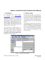
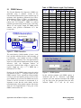
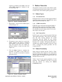
Application Note:
HFAN-9.5.0
Rev.1; 04/08
Pattern Creator/Converter Software
User Manual
Functional Diagrams
Pin Configurations appear at end of data sheet.
Functional Diagrams continued at end of data sheet.
UCSP is a trademark of Maxim Integrated Products, Inc.
LE
AVAILAB
Pattern Creator/Converter Software User Manual
1 Introduction
2 Pattern Creator
The Pattern Creator/Converter software (available
for
download
at:
http://www.maximic.com/tools/other/) was written to facilitate the
creation and use of complicated and non-standard
test patterns for evaluation of ICs, modules, and
systems used in fiber-optic, video, backplane and
other applications. This application note will step
through the features and use of the Pattern Creator /
Converter software and show examples on how to
use the program. The software has three main
sections: a Pattern Creator, a Pattern Converter and
Additional Resources / Information.
The Pattern Creator (Figure 1) allows the user to
create long binary test patterns in a text file format.
To start a new pattern, click the Output File Name
button and choose a filename and location. Once the
file location and name are selected, the file is
created. Patterns can then be added sequentially by
pressing the buttons of the various built-in pattern
sequences.
Note: This software is intended to run on a
windows-based desktop computer (Windows 98 or
newer) with a screen resolution of 800x600 or
larger. The operating system that is included with
test equipment (pattern generators, oscilloscopes,
etc.) will often lack the necessary installed window
components to allow correct operation of the
program directly on that equipment.
The sequence of the pattern created will appear in
the Pattern Sequence box and the statistics of the
pattern will be displayed in the Pattern Statistics
text box. Pressing the Done button closes the text
file that was created. More details and an example of
how to use the buttons and features of the Pattern
Creator section will be demonstrated in the
following paragraphs.
Figure 1. Pattern Creator Tab Menu
Application Note HFAN-9.5.0 (Rev.1; 04/08)
Maxim Integrated
Page 2 of 8
Table 1: PRBS Pattern Length / Tap Positions
2.1
PRBS Patterns
The Pseudo Random Bit Sequences (PRBS) are
generated using a software version of the
conventional hardware shift register with the taps of
minimum shift algorithms generated from Galoisfield arithmetic (Figure 2, Table 1, see References 1
& 2). The shift register length is determined by the
pattern title. For example, a PRBS 27-1 pattern
would be generated using a shift register 7 bits long.
Where n is the register length, the PRBS pattern
contains every possible combination of n bits
(except one).
PRBS Generation
TAP3
TAP4
n-1
TAP2
n
TAP1
OUT
n Bit Shift Register
3
2
1
SHIFT DIRECTION
XOR
IN
Register
Length
(n)
3
4
5
6
7
8
9
10
11
12
13
14
15
16
17
18
19
20
21
22
23
Pattern
Length
(2n-1)
7
15
31
63
127
255
511
1023
2047
4095
8191
16383
32767
65535
131071
262143
524287
1048575
2097151
4194303
8388607
Register Number (1 to n)
Tap1
3
4
5
6
7
8
9
10
11
12
13
14
15
16
17
18
19
20
21
22
23
Tap2
2
3
3
5
6
7
5
7
9
9
12
13
14
14
14
11
18
17
19
21
18
Tap3
Tap4
3
2
8
10
3
5
9
2
13
11
14
13
Figure 2. PRBS Generation
The mark density (100%*(number of ones / total
bits)) and the transition density (100%*(number of
bit transitions / total number of bits)) of PRBS
patterns are approximately 50%. This approximation
improves as the pattern length (shift register length)
increases. Also, the maximum number of
consecutive identical digits (CIDs) is equal to the
register length (n) (e.g. a 223-1 PRBS has a
maximum of 23 CIDs).
Pressing any of the PRBS buttons opens the option
list shown in Figure 3. Using this option list, the
PRBS sequence can be repeated an integer number
of times or the total number of bits to write of the
given PRBS can be selected. The PRBS can also be
written to the file inverted or non-inverted. It is
important to note that the mark density and the
transition density of the pattern sequence can deviate
from the 50% approximations if only part of the
PRBS is written to the file.
Application Note HFAN-9.5.0 (Rev.1; 04/08)
Figure 3. PRBS Options
In this software program, each PRBS register is
initialized with all 1’s. Therefore, each PRBS
sequence will start with the maximum CID length
(e.g. the first seven bits generated from the noninverted PRBS 2^7-1 will be all ones).
Maxim Integrated
Page 3 of 8
2.2
K28.5 Pattern
By pressing the K28.5 button, the user can add one
or multiple K28.5 sequences with the choice of
being inverted or non-inverted (Figure 4). The data
bits added for each K28.5 sequence is the entire
K28.5± pattern, where the non-inverted bits are:
1100 0001 0100 1111 1010.
Figure 6. Binary File Options
This feature can also be used to read in an existing
pattern/text file and determine its statistics. This can
be a useful tool in evaluating test files or actual data
in the system.
2.5
Figure 4. K28.5 Options
2.3
Adding Consecutive Identical Digits
The consecutive digits button lets the user add 1 to
99999 consecutive ones or zeros to the pattern
sequence (Figure 5).
Miscellaneous Test Patterns
By pressing the Misc. Patterns button, the user can
add sections of various length repeating one/zero
patterns (10, 1100, 111000, etc.), non-standard
PRBS patterns or variable bit lengths of internally
generated random bits (Figure 7).
Figure 5. CID Options
Figure 7. Miscellaneous Test Patterns
2.4
Binary Text File
The pattern creator/converter software includes the
option of inserting an existing text file. The software
will read any text file and extract the “1” and “0”
text characters from the file and insert them into the
pattern being created. The file can be written
inverted or non-inverted and then be repeated up to
999 times (Figure 6)
Application Note HFAN-9.5.0 (Rev.1; 04/08)
2.6
Pattern Creator Considerations
The following items should be considered when
creating test patterns with this software:
• The software writes the pattern to the
selected file sequentially. It is not possible to
go back and edit the file after a pattern has
been added.
• Pattern Granularity (see section 3.2)
• Pattern files greater than 2 million bits can
take a couple of minutes to write.
• The software does not allow the pattern
length to exceed 34 million bits.
Maxim Integrated
Page 4 of 8
•
•
2.7
Many pattern generators can only use
pattern files up to 8 million bits in length
and may have limitations to the number of
CIDs that they can tolerate.
Once the Done button is pressed the pattern
sequence and statistics are erased. The
information should be written down before
pressing the Done button if it will be needed
at a later time.
Example
A common use of this software is to add sections of
CIDs to existing PRBS patterns in order to test the
response of a device with data that has low
frequency content. For example, to create a 27-1
PRBS + 100CID test pattern, the following steps are
used.
Figure 9. Creator Example Step #3
4. The first sequence of the pattern is now
shown in the Pattern Sequence box and the
corresponding statistics of the pattern to this
point are shown in the Pattern Statistics
textbox (Figure 10).
1. Click the Output File Name button and
enter the name and location of the file that
will be created (Figure 8)
Figure 10. Creator Example Step #4
5. Add 100 1’s to the end of the pattern by
clicking the Consecutive Digits button,
entering 100 in the box, selecting the Ones
option and then by clicking on the OK
button (Figure 11).
Figure 8. Creator Example Step #1
2. Click the PRBS 2^7-1 button.
3. Click on the pull down menu (Figure 9) and
verify that Times to Repeat the PRBS is
selected, enter 1 in the text box, verify that
the Non-Inverted option is selected and
then click the OK button.
Figure 11. Creator Example Step #5
6. To balance the pattern, two additional
sequences need to be added. Namely, the
inverse of the first two sequences. To add
the next sequence, repeat step #3, except
with the Inverted option selected (Figure
12). Note that after OK button is clicked, the
Application Note HFAN-9.5.0 (Rev.1; 04/08)
Maxim Integrated
Page 5 of 8
sequence list adds the letters INV to the end
of the PRBS sequence to indicate it was
inverted (Figure 14).
3 Pattern Converter
The pattern Converter section of the software readsin existing patterns and converts them to one of three
formats for use with common pattern generators.
3.1
Figure 12. Creator Example Step #6
7. Repeat Step 5 except with the Zeros option
selected (Figure 13).
3.1.1 Hex Pattern Files
HEX pattern files can be used with Agilent N4901/2
and 86130 pattern generators. The HEX files can be
opened and viewed in any text editor.
3.1.2 PTRN Pattern Files
PTRN file types can be used with Agilent N4901/2
and 86130 pattern generators. The files are binary
files so they can not be read in text editors. PTRN
files should be used for longer pattern files because
they require less disk space.
3.1.3
Figure 13. Creator Example Step #7
8. The pattern is now created. As seen in the
pattern statistics, the pattern is balanced
(same number of ones and zeros). Given the
long CID sequences that were added, the
transition density is much less than 50%
(Figure 14).
9. Click the Done button to complete the
procedure. The pattern is now ready to be
used as a text file or converted to a pattern
generator test file.
Pattern Types
DAT Pattern Files
DAT file types can be used with Agilent 70843 and
70841 pattern generators. These files are also binary
files but they include different file header
information than the PTRN file type. Pattern
generators that use DAT file types have pattern store
locations 5-12 available. The pattern file name is
included in the header information of the file. If the
name is changed, the pattern generator will not
recognize the file.
3.2
Pattern Granularity
When using the Agilent 86130A, 70843 or 70841
pattern generators, the length of a user input pattern
must be a predefined multiple for a given range of
pattern lengths. As the pattern length increases, the
multiple increases as well.
Tables 2 and 3 list the pattern granularity of each
generator. This information can also be accessed
with the software by clicking the Pattern
Granularity button.
Figure 14. Creator Example Step #8
Application Note HFAN-9.5.0 (Rev.1; 04/08)
Maxim Integrated
Page 6 of 8
•
Table 2: Granularity Table (70841 / 70843)
Pattern Length (L)
(Bits)
Step Size
(Bits)
•
L < 32000
1
2
32000 L < 64000
64000 L < 128000
4
8
128000 L < 256000
256000 L < 512000
16
512000 L < 1024000
32
64
1024000 L < 2048000
2048000 L < 4096000
128
256
4096000 L 8000000*
*The Maxim pattern length for the 70841 is
4194304 bits
•
•
3.4
Table 3: Granularity Table (86130A)
Pattern Length (L)
(Bits)
L < 128000
128000 L < 256000
256000 L < 512000
512000 L < 1024000
1024000 L < 2048000
2048000 L < 4096000
4096000 L 8000000
Step Size
(Bits)
1
2
4
8
16
32
64
It can take several minutes to convert a
pattern file that is over 2 million bits in
length.
The software must first count the number of
bits in the file to verify that the pattern is the
correct type, and that it does not exceed the
maximum pattern length.
PTRN and DAT file types should be used
when possible as they take up less disk
space.
DAT files require specific filenames. The
number of the filename should be selected
before clicking the DAT button.
Example
To convert the pattern that was created in section
2.7:
1. Select the pattern generator that will be
used. For this example, we will assume the
generator is the Agilent 70843 series (Figure
16).
If the pattern does not meet these requirements, the
pattern generator may not recognize the file. The
software will verify the pattern length when doing a
conversion. If an error is found in the pattern length
a message box will appear (Figure 15) with the two
pattern lengths that meet the requirements that are
closest to the original pattern length. The pattern will
then need to be adjusted before the conversion can
take place.
Figure 16. Converter Example Step #1
2. Set the pattern store number for the DAT
file type to any number between 5 and 12 by
clicking on the up/down buttons (Figure 16).
Figure 15. Pattern Granularity Error
3.3
Additional Pattern Converter
Considerations
3. Click on the DAT button and find the binary
text file that needs to be converted and then
click on Open (Figure 17). After the Open
button is clicked, the program will count the
number of data bits in the file.
In addition to the items in sections 2.6 and 3.2, the
following items should also be noted when using the
pattern converter section of the software.
Application Note HFAN-9.5.0 (Rev.1; 04/08)
Maxim Integrated
Page 7 of 8
4 Resources/Information
The Resources/Information tab (Figure 20) includes
links to helpful Maxim Integrated Products websites,
the software license agreement and information
about the software version number.
Figure 17. Converter Example Step #3
4. Select the location where the new pattern
file should be stored and click the Save
button (Figure 18). Note: Do not change the
filename when using DAT-type pattern files.
If the name is changed, the pattern generator
will not recognize the test file.
Technical support is not available for this software.
However, if errors (bugs) are found in the evaluation
of the software or additional features are requested,
please email [email protected]
with PRBSsoft in the subject line. Any comments
submitted will be considered in future revisions of
the program.
Figure 20. Resources/Information Section
Figure 18. Converter Example Step #4
5. After clicking the Save button, the program
will then convert the file and display a
message when it has completed (Figure 19).
The pattern can now be read and used by the
pattern generator.
References:
1. The Art of Electronics: Horowitz & Hill,
Cambridge University Press – 1995
2. “Primitive Binary Polynomials”, Wayne
Stahnk, Mathematics of Computation, Vol
27, No. 124, pages 977-980 - Oct 1973
Figure 19. Converter Example Step #5
Application Note HFAN-9.5.0 (Rev.1; 04/08)
Maxim Integrated
Page 8 of 8