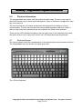
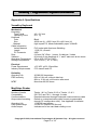
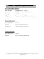
1
USER MANUAL
VersaKey™
Compact Programmable
Keyboard
Model Number
IDKA-33xxxx
80074504-001-A
04-07-2009
VersaKey™ Programmable Keyboard User Manual
FCC WARNING STATEMENT
This equipment has been tested and found to comply with the limits for a Class B digital
device, pursuant to Part 15 of FCC Rules. These limits are designed to provide reasonable
protection against harmful interference when the equipment is operated in a commercial
environment. This equipment generates, uses, and can radiate radio frequency energy
and, if not installed and used in accordance with the instruction manual, may cause harmful
interference to radio communications.
FCC COMPLIANCE STATEMENT
This device complies with Part 15 of the FCC Rules. Operation of this device is subject to
the following conditions: this device may not cause harmful interference and this device
must accept any interference received, including interference that may cause undesired
operation.
CANADIAN DOC STATEMENT
This digital apparatus does not exceed the Class B limits for radio noise for digital
apparatus set out in the Radio Interference Regulations of the Canadian Department of
Communications.
Le présent appareil numérique n’émet pas de bruits radioélectriques dépassant les limites
applicables aux appareils numériques de las classe B prescrites dans le Réglement sur le
brouillage radioélectrique édicté par les ministère des Communications du Canada.
CE STANDARDS
An independent laboratory performed testing for compliance to CE requirements. The unit
under test was found compliant to Class B.
ID TECH is a registered trademark of International Technologies & Systems Corporation.
VersaKey and Value through Innovation are trademarks of International Technologies &
Systems Corporation.
USB (Universal Serial Bus) Specification is Copyright by Compaq Computer Corporation,
Intel Corporation, Microsoft Corporation, and NEC Corporation.
Copyright © 2008, International Technologies & Systems Corp. All rights reserved.
Page 2 of 18
VersaKey™ Programmable Keyboard User Manual
LIMITED WARRANTY
ID TECH warrants to the original purchaser for a period of 12 months from the date of
invoice that this product is in good working order and free from defects in material and
workmanship under normal use and service. ID TECH’s obligation under this warranty is
limited to, at its option, replacing, repairing, or giving credit for any product which has,
within the warranty period, been returned to the factory of origin, transportation charges
and insurance prepaid, and which is, after examination, disclosed to ID TECH’s satisfaction
to be thus defective. The expense of removal and reinstallation of any item or items of
equipment is not included in this warranty. No person, firm, or corporation is authorized to
assume for ID TECH any other liabilities in connection with the sales of any product. In no
event shall ID TECH be liable for any special, incidental or consequential damages to
purchaser or any third party caused by any defective item of equipment, whether that
defect is warranted against or not. Purchaser’s sole and exclusive remedy for defective
equipment, which does not conform to the requirements of sales, is to have such
equipment replaced or repaired by ID TECH. For limited warranty service during the
warranty period, please contact ID TECH to obtain a Return Material Authorization (RMA)
number & instructions for returning the product.
THIS WARRANTY IS IN LIEU OF ALL OTHER WARRANTIES OF MERCHANTABILITY
OR FITNESS FOR PARTICULAR PURPOSE. THERE ARE NO OTHER WARRANTIES
OR GUARANTEES, EXPRESS OR IMPLIED, OTHER THAN THOSE HEREIN STATED.
THIS PRODUCT IS SOLD AS IS. IN NO EVENT SHALL ID TECH BE LIABLE FOR
CLAIMS BASED UPON BREACH OF EXPRESS OR IMPLIED WARRANTY OF
NEGLIGENCE OF ANY OTHER DAMAGES WHETHER DIRECT, IMMEDIATE,
FORESEEABLE, CONSEQUENTIAL OR SPECIAL OR FOR ANY EXPENSE INCURRED
BY REASON OF THE USE OR MISUSE, SALE OR FABRICATIONS OF PRODUCTS
WHICH DO NOT CONFORM TO THE TERMS AND CONDITIONS OF THE CONTRACT.
The information contained herein is provided to the user as a convenience. While every
effort has been made to ensure accuracy, ID TECH is not responsible for damages that
might occur because of errors or omissions, including any loss of profit or other commercial
damage, nor for any infringements or patents or other rights of third parties that may result
from its use. The specifications described herein were current at the time of publication,
but are subject to change at any time without prior notice.
ID TECH
10721 Walker Street
Cypress, CA 90630
(714)761-6368
Copyright © 2008, International Technologies & Systems Corp. All rights reserved.
Page 3 of 18
VersaKey™ Programmable Keyboard User Manual
1.0
2.0
3.0
4.0
5.0
Introduction................................................................................................................ 5
Product Configurations .............................................................................................. 5
Features .................................................................................................................... 6
Definition of Terms & Applicable Documents ............................................................ 6
Physical information .................................................................................................. 7
5.1
Keyboard layout ................................................................................................. 7
6.0
Keyboard Operation .................................................................................................. 9
6.1
Reader Configuration ......................................................................................... 9
7.0
Keyboard Programming Software.............................................................................10
7.1
Programming Application Installation ................................................................10
7.2
General Information...........................................................................................10
7.3
General Operation ....................................................................................................10
7.4
Key Selection Window.......................................................................................11
7.5
Key-name Assignment Window.........................................................................11
7.6
Programming Files ............................................................................................11
7.7
File Buttons .......................................................................................................11
7.8
Key Identification Number (Key#)......................................................................11
8.0
Keyboard Programming............................................................................................11
8.1
Two Primary Windows used for Programming ..................................................11
8.2
Programming Steps...........................................................................................12
8.3
Selecting the Key for a Key-name Assignment .................................................12
8.4
Assigning Key-name(s) to the Selected Key .....................................................12
8.5
Key-name Assignment Window Buttons............................................................12
8.6
File Operations .........................................................................................................13
8.7
Send to Keyboard..............................................................................................13
8.8
Save to File .......................................................................................................13
8.9
Open Programming File ....................................................................................13
8.10 Default All ..........................................................................................................13
8.11 Test Key ............................................................................................................13
8.12 Exit Programming Application ...........................................................................13
9.0
Troubleshooting........................................................................................................14
Appendix A: Specifications..................................................................................................15
Appendix B: MagStripe Reader Default Settings.................................................................17
Appendix C: Outline Drawing ..............................................................................................18
Copyright © 2008, International Technologies & Systems Corp. All rights reserved.
Page 4 of 18
VersaKey™ Programmable Keyboard User Manual
1.0
Introduction
ID TECH VersaKey Compact Programmable Keyboard is a card-reader-enabled data-entry
solution designed for POS and security applications. The VersaKey Compact is a fullfunction programmable keyboard with a space-saving 14” x 8” form factor, and an
integrated MagStripe reader. It is available with Smart Card, touchpad or trackball options.
Additionally, country-specific keyboard layouts in various languages are available.
The VersaKey Compact’s programmable keys are easily configured with ID TECH
KeyUtility software, which is supplied with the product or can be downloaded from the ID
TECH website. For multi-step procedures, macros can be programmed into the keyboard
to simplify data-entry process. Each programmable key accepts up to 16 key codes. Once
the key assignment is finalized, the code settings can be downloaded into the keyboard’s
non-volatile memory.
The VersaKey magnetic card reader offers full data-editing capabilities. It is fully
programmable using MagSwipe Configuration Utility available on the ID TECH website
(http://www.idtechproducts.com). Data can be formatted with user defined preamble,
postamble (a.k.a. prefix and suffix), and terminator characters to match with the format
used in specific applications.
VersaKey Programmable Keyboard is available with USB- keyboard and USB- HID
interfaces. VersaKey product with a USB-keyboard configuration always sends keyboard
and MagStripe data in scan codes format so that the MagStripe data appears as if they
were through a keyboard. For USB-HID device, VersaKey communicates MagStripe data in
ASCII characters through the USB cable, allowing the VersaKey to serve separate
keyboard and Magstripe reader functions via a single device. For additional information on
USB-HID interface communication, please refer to 80074503-001 ID TECH VersaKey USBHID interface reference manual.
Both the keyboard and the reader are industry proven solutions. Together, they deliver a
space-saving, efficient and reliable POS solution. The keyboard provides more than
20,000,000 key operations; the reader has an operational life greater than 1,000,000
swipes. The VersaKey meets FCC Class B & CE regulatory requirements. ESD immunity
is greater than 15KV with no damage to the circuits. VersaKey Keyboard is compatible with
Windows 98, 2000, XP, & Vista operating systems
2.0
Product Configurations
VersaKey Compact Programmable Keyboard comes in two standard configurations:
Model Number
Description
VersaKey with MagStripe reader (USB-Keyboard interface), with
IDKA-3344XX
touchpad
VersaKey with MagStripe reader (USB-Keyboard interface), no
IDKA-3345XX
touchpad
Copyright © 2008, International Technologies & Systems Corp. All rights reserved.
Page 5 of 18
VersaKey™ Programmable Keyboard User Manual
“xx” designates the MagStripe tracks supported. “12” = Track 1 & 2, “23” = Track 2 &3 and
“33” = Track 1, 2, & 3
3.0
Features
•
•
•
•
•
•
•
•
•
•
•
•
•
•
4.0
Full-Function Keyboard with LED status indicators
USB-Keyboard interface for Keyboard and MagStripe Reader
PC/SC interface for the Smart Card Reader
The MagStripe reader has full data output configuration programming
The optional Smart Card Reader is EMV 2000, 4.1 Type Approved
1,000,000 swipe, industry proven Magnetic Stripe Reader
1,000,000 card cycle operation for Smart Card Reader
20,000,000 key operations for each key
Function keys have removable legend caps for custom legends
Touch Pad with two buttons & software for operation & configurations
Meets FCC Class B & CE regulatory requirements
Language options are available
Programming software provide key programming & reader configuration
Industry standard default keyboard key code output
Definition of Terms & Applicable Documents
ANSI
CMOS
ESD
HOST
ISO
MTBF
RoHS
USB
American National Standard Institute
Complementary Metal Oxide Semiconductor
Electrostatic Discharge
A Personal Computer or Similar Computing Device
International Standards Organization
Mean Time Between Failures
Restrictions of Hazardous Substances
Universal Serial Bus
ISO/IEC 7813 – Identification cards, Physical Characteristic
ISO/IEC 7811 – Identification cards, Recording Techniques, Magnetic Stripe
Keyboard Key Code Specification Revision 1.3a, 3/16/2000, Microsoft Corporation
Copyright © 2008, International Technologies & Systems Corp. All rights reserved.
Page 6 of 18
VersaKey™ Programmable Keyboard User Manual
5.0
Physical information
The programmable keys come with the protective plastic caps. The key covers can be
removed from the keys to insert keyboard legends. A pair of tweezers is supplied for easy
key cover removal.
The two front feet are soft rubber and prevent the keyboard from sliding or moving
unintentionally. The two rear elevation feet are provided separately and must “snap” in
place on the under the keyboard all the way rotated to the fullest travel possible.
There are four LED indicators located on the top right corner of the keyboard; they show
the status of Num Lock, Caps Lock, Scroll Lock, and keyboard power respectively.
5.1
Keyboard layout
The layouts shown below are representative of the keyboard layouts and reader locations.
The relegendable keys are shown in a lighter gray color.
The 135-key Keyboard
Copyright © 2008, International Technologies & Systems Corp. All rights reserved.
Page 7 of 18
VersaKey™ Programmable Keyboard User Manual
The 124-key Keyboard
Copyright © 2008, International Technologies & Systems Corp. All rights reserved.
Page 8 of 18
VersaKey™ Programmable Keyboard User Manual
6.0
Keyboard Operation
To install the VersaKey, plug the keyboard into an USB port. When the VersaKey is
powered on, it performs a self-test and initiation sequence with the computer. During the
self-test, the MagStripe reader will beep. The keyboard power LED will light to indicate
power is applied.
Test the keyboard with normal use in a text editor like Word. The non-programmed keys
would not have any key codes associated and therefore does not have output. Test the
reader by swiping a magnetic stripe card through the reader slot. The magnetic stripe must
be facing toward the front of the keyboard. A beep will also sound to indicate a good read
on each magnetic track, as appropriate. If three tracks are available on the reader and all
have been read successfully, the reader will beep three times. Readers with a nonkeyboard type of communication interface must be tested using the PC MagStripe
application software; otherwise, for readers with a keyboard (scan code) output, the card
data is seen on the text editor as when testing the keyboard.
6.1
Reader Configuration
The VersaKey Reader is an intelligent magnetic stripe reader that decodes, verifies, and
transmits stripe data. The reader also provides a convenient formatting and content editing
capability for transmitted data. The MagStripe data can be edited and arranged by the
reader; characters can be added to the formatted data. The added characters form either a
prefix or a suffix to the formatted MagStripe data. To support the reader’s formatting
capability, ID TECH provides an easy to use configuration utility, MagSwipe Software.
Configuration settings can also enable the reader to work with the host system
communication port settings, data transmission intervals, or data rates for example.
MagSwipe Software supports the Windows 98, Windows ME, Windows 2000, Windows XP,
and Windows Vista operating systems. When readers are configured appropriately to an
application and computer, these configuration settings are stored in the reader’s nonvolatile memory (they are not affected by the cycling of power). MagSwipe User Guide
and Software application are available on our website at www.idtechproducts.com.
The reader is shipped from the factory with the default settings already programmed. See
Appendix B. The reader has been factory programmed with the least restricted settings,
thus making the reader able to read most standard format magnetic stripe cards out of the
box.
Copyright © 2008, International Technologies & Systems Corp. All rights reserved.
Page 9 of 18
VersaKey™ Programmable Keyboard User Manual
7.0
Keyboard Programming Software
The KeyUtility is a software application designed for the ID TECH VersaKey Compact
Programmable Keyboard. The VersaKey Compact Programmable keyboard is supplied
with standard key settings in conjunction with programmable key options. The KeyUtility
provides the user with the ability to program key settings on the keyboard. For the
programmable keys, the key outputs can be programmed into the keyboard's non-volatile
memory and can be saved to a file for use on other VersaKey Compact Programmable
keyboards.
To program the keys, the keyboard needs be connected to a PC that has the KeyUtility
installed. Each programmable key can be assigned with up to 16 key codes.
Any single key can be selected for programming from the Key Selection Window. The
setting of the keys can be reviewed and changed. After all key settings are confirmed, the
KeyUtility will program the keyboard with the current settings. Key Settings can be saved in
a file and used to program multiple keyboards with the same settings.
7.1
Programming Application Installation
The application is provided in a ZIP file or on a CD. The application is RUN by doubleclicking the setup file. Then it is installed on the PC in a defined PC file folder. Making a
shortcut on the Desktop is allowed once the application is loaded.
7.2
General Information
The CLOSE and MINIMIZE boxes in the upper right hand corner have the typical Windows
function. The RESTORE DOWN/MAXIMIZE button is functional. The File menu is a pulldown menu with ”Save to File”, "Open File", "Default All" and "EXIT" menu items.
Refer to section 6.2 about the "Save to File" function
Refer to Section 6.3 about the "Open File" function
Refer to Section 6.4 about the "Default All" function
When the CLOSE or EXIT operation is selected and a Programming file has been created
or modified, a dialog box will appear and request that the file be saved before the
application is shut down.
7.3
General Operation
Once the program has been opened, a message will appear letting the user know that the
program connecting. The application is searching for the Programmable Keyboard product.
If a Programmable Keyboard is not found, the window presents the message text "Unit Not
Found". If a Keyboard is connected and communicating properly, the welcome window
displays keyboard model and version number of the connected unit.
Copyright © 2008, International Technologies & Systems Corp. All rights reserved.
Page 10 of 18
VersaKey™ Programmable Keyboard User Manual
If the Programmable Keyboard is disconnected, the software will reset and default to
communication polling again searching for the Programmable Keyboard.
7.4
Key Selection Window
By pressing the PCs keyboard ENTER key or by clicking on the NEXT button in the
application window, the Key Selection window will appear.
A Key Selection Window is provided to view & select a programmable key on the keyboard.
The keyboard layout shown would be the same as the connected keyboard
7.5
Key-name Assignment Window
Once a programmable key is selected, the Key-name Assignment Window is opened for
the user to view and edit the key-names. Assign the Key-name by typing on the physical
keyboard or selecting keys from the virtual on screen keyboard.
7.6
Programming Files
Programming files are created during the key selection and Key-name assignment process.
At the end of the process, the Programming file can be saved and/or sent to the keyboard.
The file can be saved and used to program other keyboards of the same type.
Programming files are unique to a specific Programmable Keyboard model number and
cannot be used on a keyboard with a different model number.
7.7
File Buttons
Files can be saved and opened later to program a connected keyboard. To set the
Programmable Keyboard back to the default key-names, click on the DEFAULT ALL button
on the screen.
7.8
Key Identification Number (Key#)
This number is used in the Key Programming Window as a key selection identifier. The
keys on the keyboard are numbered, starting with Key No. 1, which is located on the top
left hand side. The keys are numbered sequentially across the row from left to right.
The first left-hand key of the next row is assigned the next sequential number. This
numbering assignment continues from left to right from one row to the next. Any key
occupying more than one row position is assigned the appropriate Key # for the position it
occupies in the upper row.
8.0
Keyboard Programming
8.1
Two Primary Windows used for Programming
The Programmable Keyboard comes in two form factors. One is equipped with 54
programmable and relegenable keys and the other equipped with 60 programmable and
relegenable keys. These programmable and relegenable keys are represented in white in
the Key Selection Window. The Key Selection window indicates the type of keyboard that
Copyright © 2008, International Technologies & Systems Corp. All rights reserved.
Page 11 of 18
VersaKey™ Programmable Keyboard User Manual
you plugged into the PC. The other keys represented in black are fixed and cannot be
changed. The Programmable Keyboard and corresponding programming application will
sync together once the Keyboard is successfully plugged into the PC.
8.2
Programming Steps
Keys are programmed one at a time. The process is to select a key on the Key Selection
Window, assign one or more Key-name(s) from the Key-name Assignment Window
(Maximum of 16 characters per Key-name assignment.), click "OK" to complete
assignment(s), and repeat this process for all the keys to be programmed. After all keys
and their Key-name selections are completed, the keyboard is programmed using the
"Send to Keyboard" button. All the successfully programmed keys will be identified in
green.
8.3
Selecting the Key for a Key-name Assignment
From the Key Selection Window, select the specific key to be programmed by clicking on
the desired programmable key. Immediately the Key-name Assignment Window will open.
Keys with no programmed Key-name will be in white. Keys that have already been
programmed with Key-names will be represented in green. Keys with Key-name(s)
assigned but have not been sent to the keyboard would be in yellow.
8.4
Assigning Key-name(s) to the Selected Key
The Key-name Assignment Window has a virtual keyboard and a text box that displays the
Key-names. The virtual keyboard contains all the keys supported in Key-names
assignment.
Each plastic cap covered key can be assigned a Key-name. It is suggested to indentify the
physical key by including a label under the plastic key cover. The key cap can be removed
using the tweezers that are shipped with the unit.
The Key-names can be selected by clicking on the virtual keys on screen or by entering the
keys from the physical keyboard. In both cases, the key being programmed would go from
white to yellow on the virtual keyboard.
*Notice: The “00” key (available on certain keyboard configurations only) cannot be used to
program the keys with two zeros. User must enter zero twice using the “0” key.
8.5
Key-name Assignment Window Buttons
•
•
•
The LOOK-UP button opens a third window with a scrolling chart that lists each keyname and corresponding USB outputs. The LOOK-UP function is provided for
reference only.
The CLEAR button removes the highlighted Key-name from the list. Each key-name
can be highlighted by a mouse click.
The CLEAR ALL button removes all the key-names that are programmed to the key.
Copyright © 2008, International Technologies & Systems Corp. All rights reserved.
Page 12 of 18
VersaKey™ Programmable Keyboard User Manual
•
•
8.6
The CLOSE button closes the Key Assignment window. Any Key-name assignments
are abandoned and no information will be saved.
The OK button concludes the Key-name selection process for the selected Key#.
File Operations
The key assignment can be saved in a file and used to program additional keyboards.
8.7
Send to Keyboard
This button sends the assigned key-names to the connected keyboard. There is a pop up
window that advises the user that the keyboard will be programmed. There is another
notice that will pop up to confirm the programming is completed or if there is a
programming failure.
8.8
Save to File
The SAVE to FILE button saves the current key programming information in a file. A File
Save dialog box is opened for filename entry. The file extension is always unique and fixed
to the connected keyboard model. Any added extension is ignored.
8.9
Open Programming File
The "Open File" button opens a file selection box. Opening a new file erases all the
unsaved Key-name settings. There is no warning dialog box. After the file is opened, the
Key Selection Window and the Key-name Assignment Window will display the programmed
key settings saved in the opened file.
8.10
Default All
The DEFAULT ALL button uses a default key programming file from the Utility. The default
file restores the connected keyboard back to the factory key settings and erases any
previous key settings that may have been programmed.
8.11
Test Key
The Test Key button provides a window to test the programmed keys once the change has
been sent to the keyboard.
8.12
Exit Programming Application
When the "Exit" is selected and the current programming file has not been saved, a window
that says “Save current programming file?” would pop up. The user can choose to save the
keyboard settings to a file.
Copyright © 2008, International Technologies & Systems Corp. All rights reserved.
Page 13 of 18
VersaKey™ Programmable Keyboard User Manual
9.0
Troubleshooting
Troubleshooting assistance for common VersaKey keyboard problems:
• The data from the reader is not as expected.
The reader is shipped from the factory with the default settings already programmed. See
Appendix B for the Default Settings. The default settings can be customer modified by
using the MagSwipe Configuration Utility.
• The reader does not output data.
The reader will beep when power is applied to the VersaKey. The reader will also beep for
each track correctly read from a magnetic stripe. Use a known good credit card to test the
reader operation. Insure that a text input application (such as Windows Notepad) is open
and selected during the test.
• The keyboard does not function with the computer.
If the power indicator LED is off, the keyboard may not be fully connected to the computer.
Check the connections as well as the computer power. If the power LED is on but the
keyboard is not functioning,, the driver may not be loaded properly on the computer. Check
the Device Manager in Hardware Properties of the computer. The driver is a standard
windows driver for operating systems Windows 98SE and later.
Copyright © 2008, International Technologies & Systems Corp. All rights reserved.
Page 14 of 18
VersaKey™ Programmable Keyboard User Manual
Appendix A: Specifications
VersaKey Keyboard
Mechanical
Keyswitch
Total Travel
Operating Force
Keyboard
Color
Size
Material
Cable Information
Jacket Material
Length
PC Connector
Drop
Vibration
Operating Temperature
Storage Temperature
PVC jacket with Aluminum Shielding
1.5 M (5ft.) Overall
USB
610 mm (24”) Drop: 1 corner, 2-sidelines, 3-sides
60 Hz/sec 3 mm amplitude X, Y and Z each axis at two hours
0°C to 40°C (32°F to 104°F)
-20°C to 40°C (- 4°F to 104°F)
Electrical
Power Requirement
Industry Requirements
+5.0 VDC ±10%, 60ma Max
FCC class B and CE
Reliability
Operating Life
ESD Immunity
MTBF
4.0 + 0.5 mm
50 + 7g
Black
469.9 mm (L) x 203.9 mm (W) x 42.8 mm (H)
High Impact PS, Meets flammability spec. UL94HB
20,000,000 keystrokes
0KV to 8 kV min, without data loss.
8KV to 15 kV min, will function after reset
More than 60,000 hours
MagStripe Reader
Number of tracks
Compatibility
Communications
Output data formatting
Operating Life
Card speed range
Audio beeper
Tracks 1 & 2 or Tracks 2 & 3 or Tracks 1, 2 & 3
ISO 7810 and 7811-1 through -6 cards.
Decoded data sent through Keyboard communications cable.
Default or customized data output format; programmable
through PC configuration utility. See Appendix for defaults
1,000,000 card swipes
3 to 60 IPS (Inches Per Second)
Indicates error free card data reading or not
Copyright © 2008, International Technologies & Systems Corp. All rights reserved.
Page 15 of 18
VersaKey™ Programmable Keyboard User Manual
Smart Card Reader (Optional)
Smart card types
Microprocessor type, T=0 & T=1
Compatibility
ISO 7816-1thru 6 cards. EMVCo Compliant
Operating Life
1,000,000 card swipes
LED (green)
There is a card seated LED next to the smart card slot;
the LED is on when the card is seated and powered.
Touchpad (Optional)
Max Tracking Speed
250 mm/s
Resolution
Dynamic resolution, 100-300 dpi
Operating Life
1,000,000 tapping/abrasion cycles
Trackball (Optional)
Max Tracking Speed
300 rpm
Resolution
800 +/- 30 counts per ball revolution
Copyright © 2008, International Technologies & Systems Corp. All rights reserved.
Page 16 of 18
VersaKey™ Programmable Keyboard User Manual
Appendix B: MagStripe Reader Default Settings
The Reader is shipped from the factory with the following magnetic stripe default settings
programmed.
Default Functional Settings
Function
Terminal Type
Beep Volume
Character Delay
Track Selection
Data Output Format
Track Separator
MSR Reading
Decoding Method
Terminator ID
Default Value
PC/AT (Auto Selects)
High
2 ms
Any Track
ID TECH Format
See Section 7.3
Enable
Decoding in Both Directions
ENTER (Keyboard)
Magnetic Stripe Data Output Format
Magnetic Track Basic Data Output Format
Track 1: <SS1><T1 Data><ES><TS>
Track 2: <SS2><T2 Data><ES><TS>
Track 3: <SS3><T3 Data><ES><Terminator>
Where:
SS1(start sentinel track 1) = %
SS2(start sentinel track 2) = ;
SS3(start sentinel track 3) = ; for ISO, % for AAMVA
ES(end sentinel all tracks) = ?
<TS> = <ENTER> key or CR
Terminator = <ENTER> key or CR
Start or End Sentinel: Characters in encoding format which come before the first data
character (start) and after the last data character (end), indicating the beginning and end,
respectively, of data.
Track Separator: A designated character that separates data tracks.
Terminator: A designated character that comes at the end of the last track of data in order
to separate card reads.
LRC: Check character, following end sentinel. (The reader will verify it when decoding, but
this will not be sent as part of the data.)
Copyright © 2008, International Technologies & Systems Corp. All rights reserved.
Page 17 of 18
VersaKey™ Programmable Keyboard User Manual
Appendix C: Outline Drawing
VersaKey programmable keyboard with Smart Card reader and touchpad is shown.
Copyright © 2008, International Technologies & Systems Corp. All rights reserved.
Page 18 of 18