1
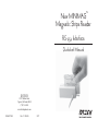
TM
New MINIMAG
Magnetic Stripe Reader
RS-232 Interface
Quickstart Manual
ID TECH
10721 Walker Street
Cypress, California 90630
(714) 761-6368
www.idtechproducts.com
80066507-001
Rev. C R04/06
#417
AGENCY APPROVED
DEFAULT SETTINGS TABLE
Specifications for subpart B of part 15 of FCC rule for a Class A computing
device.
The MiniMag reader is shipped from the factory with the following default
settings already programmed:
LIMITED WARRANTY
Magnetic Track Basic Data Format
Track 1: <SS1><T1 Data><ES><CR>*
Track 2: <SS2><T2 Data><ES><CR>*
Track 3: <SS3><T3 Data><ES><Enter>*
where:
SS1(start sentinel track 1) = %
SS2(start sentinel track 2) = ;
SS3(start sentinel track 3) = ; for ISO, ! for CDL, %
for AAMVA
ES(end sentinel all tracks) = ?
CR = Carriage Return
ID TECH warrants to the original purchaser for a period of 24 months from
the date of invoice that this product is in good working order and free from
defects in material and workmanship under normal use and service. ID
TECH’s obligation under this warranty is limited to, at its option, replacing,
repairing, or giving credit for any product which has, within the warranty
period, been returned to the factory of origin, transportation charges and
insurance prepaid, and which is, after examination, disclosed to ID TECH’s
satisfaction to be thus defective. The expense of removal and reinstallation of
any item or items of equipment is not included in this warranty. No person,
firm, or corporation is authorized to assume for ID TECH any other liabilities
in connection with the sales of any product. In no event shall ID TECH be
liable for any special, incidental or consequential damages to Purchaser or
any third party caused by any defective item of equipment, whether that
defect is warranted against or not. Purchaser’s sole and exclusive remedy for
defective equipment, which does not conform to the requirements of sales, is
to have such equipment replaced or repaired by ID TECH. For limited warranty service during the warranty period, please contact ID TECH to obtain
a Return Material Authorization (RMA) number & instructions for returning
the product.
THIS WARRANTY IS IN LIEU OF ALL OTHER WARRANTIES OF
MERCHANTABILITY OR FITNESS FOR PARTICULAR PURPOSE.
THERE ARE NO OTHER WARRANTIES OR GUARANTEES, EXPRESS
OR IMPLIED, OTHER THAN THOSE HEREIN STATED. THIS PRODUCT IS SOLD AS IS. IN NO EVENT SHALL ID TECH BE LIABLE FOR
CLAIMS BASED UPON BREACH OF EXPRESS OR IMPLIED WARRANTY OF NEGLIGENCE OF ANY OTHER DAMAGES WHETHER DIRECT, IMMEDIATE, FORESEEABLE, CONSEQUENTIAL OR SPECIAL
OR FOR ANY EXPENSE INCURRED BY REASON OF THE USE OR
MISUSE, SALE OR FABRICATIONS OF PRODUCTS WHICH DO NOT
CONFORM TO THE TERMS AND CONDITIONS OF THE CONTRACT.
Baud Rate:
Data Bits:
Parity:
Handshaking:
Stop Bits(s):
x-On:
x-Off:
9600 bps
8
None
x-On/x-Off
1
DC1 (Hex 11)
DC3 (Hex 13)
Start or End Sentinel: Characters in encoding format which come before the first
data character (start) and after the last data character (end), indicating the beginning and end, respectively, of data.
Track Separator: A designated character which separates data tracks.
Terminator: A designated character which comes at the end of the last track of data,
to separate card reads.
LRC: Check character, following end sentinel.
CDL: Old California Drivers License format.
*Note: The <CR> characters (shown above) between tracks 1 & 2 and 2 & 3
denote the default character for this position, the Track Separator position. The
<CR> shown for track 3 denotes the default character for this position, the Terminator position.
8
RUNNING THE UTILITY
The reader is shipped from the factory with the “default configuration”
programmed. The default configuration has the least restrictive settings, thus
making it able to read all data of a standard encoded magnetic stripe card.
See the default settings table for details.
The configuration software can be downloaded from the ID TECH website.
From the website, download the Configuration Utility ZIP file into a temporary file folder on your local hard drive. Double click the downloaded self
extracting file and follow the screen prompts to expand the Zip file and run
the SETUP.EXE application.
The install wizard creates two new folders on the C: Drive. The new folder
“IDTECH” and a sub-folder “MagSwipe Configuration Utility” are created in
the “Program Files” folder.
At the finish of the installation process, an “MagSwipe Configuration Utility” menu is installed in the programs folder of the Start menu. Connect
the reader to the host computer and ensure it is getting power. Point to the
“MagSwipe Configuration Utility” menu and click on the IDT icon.
The utility will start at the Home Page with a menu on the left border. Point
and click on the menu items as needed. For information on using the utility,
point and click the HELP menu selection.
7
©2006 International Technologies & Systems Corporation. The information
contained herein is provided to the user as a convenience. While every effort
has been made to ensure accuracy, ID TECH is not responsible for damages
that might occur because of errors or omissions, including any loss of profit
or other commercial damage. The specifications described herein were current at the time of publication, but are subject to change at any time without
prior notice.
ID TECH is a registered trademark of International Technologies & Systems
Corporation. MiniMag and Value through Innovation are trademarks of
International Technologies & Systems Corporation.
Windows is a registered trademark of Microsoft Corporation. The USB (Universal Serial Bus) Specification is Copyright© 1998 by Compaq Computer
Corporation, Intel Corporation, Microsoft Corporation, NEC Corporation.
SPECIFICATIONS
Power Requirements: 5 VDC +/-10% (50mV ripple maximum).
Ground 0 VDC (GND).Chassis ground connected
to GND and magnetic head case.
Operating Current:
About 40mA for decoded magnetic stripe (three
tracks).
External Power
Supply:
5 VDC/350mA
Operating
Temperature:
32° F to 131° F (0° C to 55° C).
Storage Temperature: -22° F to 158° F (-30° C to 70° C).
Relative Humidity:
Maximum 95% non-condensing.
Magnetic Head Life:
1,000,000 passes minimum.
Rail and Cover Life:
1,000,000 passes minimum.
Magnetic Stripe
Recording Method:
MAGSWIPETM CONFIGURATION UTILITY
The magnetically encoded data on the magnetic stripe can be decoded (read)
by magnetic card readers. The stripe data has a fixed format defined by the
ISO standards. The ISO fixed format is not always convenient or useful for
card reading applications. The solution is for the card reader to decode the
stripe data and then arrange the data into useful format and content. The
reader-formatted data is transmitted from an intelligent communication
interface.
The MiniMag is an intelligent magnetic stripe reader, which provides extensive formatting capability. In addition, characters can be added to the formatted data. To support the formatting capability, ID TECH provides an easy to
use Configuration Utility software application. New file saving capabilities
allow configurations to be saved and used again without having to repeat the
full configuration process with each reader.
The Configuration Utility supports all reader interfaces. The operating systems supported are Windows 98, Windows 2000, and Windows XP.
Two-frequency coherent phase (F2F) compatible
with ISO 7811, ANSI, AAMVA, and California
DMV.
Maximum Number
of Tracks:
3 tracks.
Swipe Speed:
3 to 60 inches per second, bidirectional.
Card Thickness:
.015 to .045 inches.
Slot Width:
.050 inches.
Dimensions:
Length: 3.54 inches (90mm). Width: 1.34 inches
(34mm). Height: 1.10 inches (28mm).
Weight:
4.6 oz.
Cable Length:
6-foot straight cable.
1
6
TROUBLE SHOTTING PROCEDURES
DESCRIPTION
The troubleshooting process can be simplified by reviewing these reader
operations.
The MiniMag™ compact magnetic stripe reader can read 1, 2,
or 3 tracks of magnetic stripe information. In addition, it has full
data editing capabilities.
The unit should emit one long beep when power is first applied. If it does not,
then the unit is not receiving power. Check the power supply connections.
Once it has been confirmed that the unit is correctly powered, swipe a credit
card. The LED will go off while decoding, then light green to indicate a
“good read,” or red to indicate a “bad read.”
Once the unit has indicated a “good read,” then proceed to check the interface
configuration.
Installation of the reader is generally trouble free, but there are some considerations if problems occur.
The unit is fully programmable. The data can be formatted with
preamble/postamble and terminator characters to match the
format expected by the host.
The MiniMag can be connected to a host computer via an
RS-232 input port. When the reader is connected as an RS-232
device, a separate power supply must be used.
Does the baud rate , data bits number & parity match between reader
and host?
Is the host set-up for card reader operation - Is the card reader application running?
Does the reader configuration match the host application requirements?
5
2
HOST CONNECTIONS
CONFIGURATION
The MiniMag reader is connected to the host computer’s RS-232
communications port. The cable has a DB-9 connector at one
end, and is connected to the reader at the other end. (An adapter
can be used to connect to a DB-25 RS-232 port.)
The MiniMag must be appropriately configured to your application.
Configuration settings enable the reader to work with the host system.
These settings are programmed into the reader using the Configuration
Utility Program. Once programmed, these configuration settings are
stored in the reader’s non-volatile memory.
Data is transmitted to the host in an ASCII data format. The
reader’s output can be formatted with terminating characters and
special preamble and/or postamble character strings to match the
data format expected by the application.
The MiniMag is shipped from the factory with the default settings
already programmed. For a table of the default settings, see the Default
Settings Table. Use the configuration utility to change reader configuration. See Page 6.
The terminal must be configured to accept the data and to perform the appropriate processing. Care must be taken to ensure
that the RS-232 parameters (baud rate, data bits, Start/Stop characters, parity, and handshaking method) match those expected
by the terminal.
OPERATION
Use the MagSwipe Configuration Utility Application to program
the reader, and a communication program (such as Procomm or
Hyperterminal) to display the data.
2. To read a card, slide the card, in either direction, through the reader
slot, with the magnetic stripe facing the magnetic head.
The MiniMag magnetic stripe reader is easy to operate. Just follow these
steps:
1. Make sure the reader is properly cabled and is receiving sufficient
power. (See Troubleshooting if there is a cabling or power problem.)
3. While swiping the card through the reader, the LED will go off.
There is insufficient power available on a standard RS-232 serial
port to power the MiniMag, so an external wall-mounted power
module must be used. Connect the power cable from this unit to
the power receptacle located on the DB-9 connector. Care must
be taken to ensure the power module operates at less than +5
volts.
3
4. Once the entire magnetic stripe has been read, the LED indicator will
light up as green to signal a “good read.” If a good read is not obtained,
the LED indicator will light up as red for 1/2 second.
5. A beep will also sound to indicate a good read on each track. If all
three tracks have been read successfully, the reader will beep three times.
4