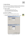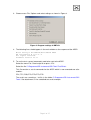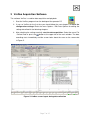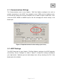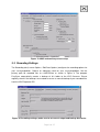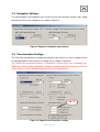
1
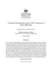
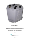
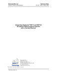
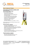
FIELAX Gesellschaft für wissenschaftliche Datenverarbeitung mbH
Schleusenstr. 14, D-27568 Bremerhaven, GERMANY
Fon: +49 (0)471 30015-0, Fax: +49 (0)471 30015-22
Mail: [email protected]
Acoustic Doppler Current Profiler
ADCP
on
RV “Heincke”
Contact:
FIELAX Gesellschaft für wissenschaftliche Datenverarbeitung mbH
Schleusenstr. 14, D-27568 Bremerhaven, GERMANY
Fon: +49 (0)471 30015-0, Fax: +49 (0)471 30015-22
Mail: [email protected]
Ref.: RV Heincke_ADCP_Support.pdf
Vers.: 1
Date: 03.04.2012
Status: final
Beneficiary: FIELAX GmbH; IBAN: DE73 2924 0024 0340 8333 00; BIC: COBADEFFXXX
Bank account: Commerzbank AG Bremerhaven, BLZ 292 400 24, Account-NR.:34 08 333
UST-ID: DE221948243, ST-NR: 75 570 10941 FA Bremerhaven, HR-NR: HRB 3506
Managing directors: Dr. Regina Usbeck, Dr. Jörg Hofmann, Roland Pallutz
Contents
1
ADCP Installation Overview ......................................................................................... 3
1.1
Sensor Equipment ................................................................................................... 3
1.2
Sensor Structure...................................................................................................... 3
1.3
Software .................................................................................................................. 4
2
System Startup............................................................................................................. 5
2.1
Switch on ADCP ...................................................................................................... 5
2.2
System Test (BBTalk) .............................................................................................. 5
3
VmDas Acquisition Software ........................................................................................ 7
3.1
Communications Settings ........................................................................................ 8
3.2
ADCP Settings......................................................................................................... 8
3.3
Recording Settings .................................................................................................. 9
3.4
Navigation Settings.................................................................................................10
3.5
Transformation Settings..........................................................................................10
3.6
Averaging Settings..................................................................................................11
3.7
Data Screening Settings .........................................................................................11
4
WinADCP....................................................................................................................12
5
Appendix .....................................................................................................................13
5.1
Result of BBTALK...................................................................................................13
Page 2 of 15
1 ADCP Installation Overview
1.1 Sensor Equipment
The following sensors are installed on the FS “Heincke”:
Table 1: Sensor specification
Sensor
Model
ADCP 150 kHz
Teledyne RDI
- vessel mounted -
OceanSurveyor
ADCP 600 kHz
Teledyne RDI
- portable for moon pool -
Workhorse
Inertial Navigation System
IXSea Phins
(INS)
Primary Positioning Unit
Trimble SP461
Secondary Positioning Unit
DEBEG/
Leica
Details from Manufacturer
Range: 400 m
Vertical resolution cell size: 4-8 m
Velocity accuracy: ±1.0%
Range: 50 m
Vertical resolution cell size: 2 m
Velocity accuracy: 0.3% of the water velocity
relative to the ADCP ±0.3cm/s
Heading accuracy: 0.05 deg (without aiding)
Roll, Pitch accuracy: 0.01 deg
Heave accuracy: 5 cm or 5%
Primary Positioning system DGPS
0.5 – 3 m accuracy
Secondary Positioning system GPS
5 – 15 m accuracy
This manual will currently focus on the 150 kHz vessel mounted ADCP.
1.2 Sensor Structure
Figure 1 shows the sensor structure of the ADCP hardware and Figure 2 shows the
installation in the laboratory. The 150 kHz transducer is hull mounted. Its deck unit is
permanently installed in the server rack next to the operator PC. The 600 kHz transducer is
portable. It has to be mounted in the moon pool. The installation of its deck unit has to be
done by AWI/FIELAX before the cruise. The operator PC receives ADCP data from one
ADCP deck unit at a time, position information from the GPS Debeg receiver OR the Trimble
DGPS receiver as well as attitude data (heading) from the Ixsea PHINS III Inertial navigation
system (INS). Only one of the two GPS receivers can be selected as the positioning input.
This can be done by a switch, which is installed on the bridge. However we recommend
using the Trimble GPS as it provides a more accurate position than the Debeg GPS so make
sure the switch is set accordingly. Recorded data should be regularly copied to the network
shares of the XDC storage server.
Page 3 of 15
GPS
DGPS
Debeg
Trimble
INS
Ixsea
ADCP
Operator PC
XDC
storage
server
Switch Selector _/_
Deck Unit
ADCP 150
Deck Unit
ADCP 600
ADCP 150 kHz
Transducer
hull mounted
ADCP 600 kHz
Portable for
moon pool oper.
Figure 1: Sensor dependencies
ADCP 150kHz
Deck Unit
Displays:
EK60
CTD Deck Unit
ADCP
CTD
CTD PC
ADCP operator PC
EK PC
GAPS / Scanmar PC
Figure 2: Installation in the laboratory
1.3 Software
The software VmDas (Vessel-mount data acquisition system) is used for data acquisition and
configuration of the ADCP. The software WinADCP can be used for visualization and export
of recorded raw data. Both software packages are installed on the ADCP operator PC.
Page 4 of 15
2 System Start-up
This manual is construed for the specific use of the ADCP on RV “Heincke” and focuses on
the most important parameters to be looked after during data acquisition. We recommend to
additionally read the VmDas Quick Start Guide and VmDas User Guide.
2.1 Switch on ADCP
1. Power up the ADCP operator PC (Figure 2, right).
For username and password please ask the captain.
2. Power up the deck unit in the server rack (Figure 2, right)
2.2 System Test (BBTalk)
Before you start a survey you should perform a hardware system test.
1. Start the BBTalk program from the desktop of the operator PC.
2. Connect to the ADCP unit by selecting the settings as shown in Figure 3.
Figure 3: Serial connection settings in BBTalk
Page 5 of 15
3. Choose menu File / Options and select settings as shown in Figure 4.
Figure 4: Program settings in BBTalk
4. The following lines should appear in the main window as the response of the ADCP:
Ocean Surveyor Broadband/Narrowband ADCP
RD Instruments © 1997-2002
All rights reserved.
Firmware Version 23.17
5. To run the tests several commands need to be sent to the ADCP.
Select the menu File / Send script file or press <F2>.
Select the file C:\Programme\RD Instruments\RDI Tools\TestOS.rds.
This file contains a set of commands for the ADCP which is now executed one after
another:
CR1, TS?, PS0, PT8, PT9, PT3, PT6.
The results are saved to a *.txt file in the folder C:\Programme\RD Instruments\RDI
Tools\. See attachment 5.1 for a detailed test result example.
Page 6 of 15
3 VmDas Acquisition Software
The software VmDas is used for data acquisition and playback.
1. Start the VmDas program from the desktop of the operator PC
2. If you run VmDas for the first time you should follow the next chapters to check the
configuration settings! Enter the menu Options / Edit Data Options for editing the
settings described in the following chapters.
3. After checking the settings carefully start the data acquisition. Select the menu File
/ Collect Data or press the
button at the upper left of the main window. The data
recording starts immediately and the screen looks about the same as the screenshot
in Figure 5.
Figure 5: VmDas screen layout during data collection
Page 7 of 15
3.1 Communications Settings
The Communications tab (in menu Options / Edit Data Options) configures the serial or
network connections to the ADCP, the navigation sensor (GPS) and the heading sensor.
Ensure that the settings for the three COM ports are as shown in Figure 6 (red circle). If not,
select the ADCP, NMEA1 or NMEA2 input on the left and apply the correct settings in the
bottom part.
Figure 6: Required communication settings (red circle)
3.2 ADCP Settings
The ADCP Setup tab (in menu Options / Edit Data Options) configures the ADCP operation
and auxiliary sensors. Configure as shown in Figure 7 or adjust the settings according to
your requirements. Optionally you can load settings from a file by selecting “Use File” in the
bottom part of the window.
Page 8 of 15
Figure 7: ADCP and auxiliary sensor setup
3.3 Recording Settings
The Recording tab (in menu Options / Edit Data Options) configures the recording options for
your survey/expedition. Choose an adequate name for your survey/expedition. Set the
primary path for recorded files to c:\ADCP\Data as shown in Figure 8. The program
EasySync automatically creates a backup of this folder to the XDC fileserver. Please
regularly check if the backups are created or ensure a manual backup of your recorded files
from the ADCP operator PC!
Figure 8: Recording settings; make sure to set correct output and backup directories.
Page 9 of 15
3.4 Navigation Settings
This tab configures the navigation input sources for the ship’s position and the ship’s speed
over ground. Ensure the settings are as shown in Figure 9.
Figure 9: Required navigation input settings
3.5 Transformation Settings
The Transform tab configures heading and roll/pitch input sources as well as angular offsets
for each parameter. Please ensure all settings are as shown in Figure 10.
The 150 kHz hull mounted transducer is mounted 45° relative to the ship’s longitudinal axis
(bow-stern) which has been detected by a bottom and water track measurement. Ensure this
offset is given as the EA Heading Alignment Error in the configuration!
45°!!!
Figure 10: Required transformation settings
Page 10 of 15
3.6 Averaging Settings
This tab (in menu Options / Edit Data Options) configures the averaging of the ADCP raw
data. Configure as shown in Figure 11 or adjust the settings according to your requirements.
The settings will not affect the raw data.
Figure 11: Averaging settings, adjustable to your requirements
3.7 Data Screening Settings
The Data Screening tab (in menu Options / Edit Data Options) configures the screening
settings for the visualization of the ADCP raw data. Adjust these settings according to your
requirements.
You can set limits for RSSI (amplitude), correlation, percent good, error velocity, vertical
velocity and fish screening. If the raw values are below the selected minimum limits the
values will not be displayed nor included in the short time and long time averages. The raw
data is of course not affected by these settings.
Page 11 of 15
4 WinADCP
The WinADCP software can be used for visualization and export of the recorded ADCP data
(screenshot in Figure 12). Please read the WinADCP User Manual for help on how to use
the software.
Figure 12: Screenshot of WinADCP during data replay
Page 12 of 15
5 Appendix
5.1 Result of BBTALK
The listing below shows the communication between PC and ADCP after running the
commands from the file TestOS.rds.
[============================================================== ]
[ OS ADCP Test
[ *************
[
[ The following tests are basic tests which will confirm that your system
[ is ready for use. Some tests will need to be run with the system in ]
[ water. You will be prompted when this is necessary. ]
[ ]
[ Connect the OS ADCP to power and the PC as described in the manual. ]
[ Turn on power to the OS ADCP. ]
[ ]
[ The results of all tests will be printed to the screen and saved to the ]
[ log file OS_TESTS.TXT. A file called OS_TESTS.TXT with the results of ]
[ this test will be created in the same directory as the BBTALK program ]
[ is running from. ]
[ ]
[ The following tests will be performed: ]
[ ]
[ PT8 RAM Verification Test ]
[ PT9 ROM Verification Test ]
[ PT3 Interference Verification Test ]
[ PT6 Bandwidth Verification Test ]
[ ]
[ Program is delaying 20 seconds before continuing. ]
[ Press <Enter> to continue. ]
[ ========================================================================]
[ ]
[ Sending a break to Wake Up the System ]
Ocean Surveyor Broadband/Narrowband ADCP
RD Instruments (c) 1997-2002
All rights reserved.
Firmware Version: 23.14
>
[ ======================================================================= ]
[ ]
[ Restoring factory defaults into temporary memory for TEST. ]
[ ]
CR1
[Parameters set to FACTORY defaults]
>
[ ======================================================================= ]
[ ]
[ Collecting system specific data. ]
TS?
TS 04/06/19,12:00:19.87 --------- Set System Date and Time
> PS0
Frequency: 153600 HZ
Configuration: 4 BEAM, JANUS
Transducer Type: ROUND 32x32
Beamformer Rev: A02 or later
Beam Angle: 30 DEGREES
Beam Pattern: CONVEX
Orientation: DOWN
CPU Firmware: 23.14
FPGA Version: XC
Sensors: TEMP SYNCHRO
>
[ ======================================================================= ]
[ ]
[ Starting the RAM and ROM Tests. ]
PT8
>PT9
>
Page 13 of 15
[ ]
[ Both of the above test should display a PASS condition. You can review ]
[ the file OS_RSLTS.TXT to verify results. Consult your Technical ]
[ Manual for trouble shooting tips if this test did not pass. ]
[ ]
[ Program is delaying 10 seconds before continuing. ]
[ Press <Enter> to continue. ]
[ ======================================================================= ]
[ ]
[ PT3 -- Interference Verification Test ]
[ The following tests will verify that the internal electronics are ]
[ not be interfered with. These tests are best run when the transducer ]
[ face is submerged in water. A bucket of water deep enough to cover ]
[ the transducer beams is all that is needed. If done in air these tests ]
[ will fail. Be sure that all sonar devices and any other device which ]
[ may emit a signal that can interfere with the ADCP is turned off. This ]
[ includes some PC monitors. ]
[ ]
[ Program is delaying 10 seconds before continuing. ]
[ Press <Enter> to continue. ]
[ ======================================================================= ]
[ ]
[ Sending a break to Wake Up the System ]
Ocean Surveyor Broadband/Narrowband ADCP
RD Instruments (c) 1997-2002
All rights reserved.
Firmware Version: 23.14
>
[ ======================================================================= ]
[ ]
[ Starting the Interference Test.]
PT3
Correlation Magnitude:
........
Lag Bm1 Bm2 Bm3 Bm4
0 1.00 1.00 1.00 1.00
1 0.81 0.81 0.81 0.81
2 0.40 0.42 0.42 0.42
3 0.09 0.11 0.12 0.10
4 0.05 0.04 0.02 0.03
5 0.04 0.04 0.02 0.03
6 0.01 0.02 0.01 0.00
7 0.01 0.03 0.02 0.02
RSSI: 15 22 21 27
PASSED
>
[ ]
[ Review the file OS_RSLTS.TXT to verify results. Compare the results ]
[ from the above test to your Technical Manual. Remember that this test ]
[ will fail unless the transducer is immersed in water and if there are ]
[ external devices operating at the same time. Consult your Technical ]
[ Manual for trouble shooting tips if this test did not pass. ]
[ ]
[ Program is delaying 10 seconds before continuing. ]
[ Press <Enter> to continue. ]
[ ======================================================================= ]
[ ]
[ PT6 -- Bandwidth Verification Test ]
[ The following tests will verify that the transducer and its receive ]
[ circuitry are working properly. These tests are best run when the ]
[ transducer face is submerged in water. A bucket of water deep enough ]
[ to cover the transducer beams is all that is needed. If done in air ]
[ these tests will fail. Be sure that all sonar devices and any other ]
[ device which may emit a signal that can interfere with the ADCP is ]
[ turned off. This includes some PC monitors. ]
[ ]
[ Program is delaying 10 seconds before continuing. ]
[ Press <Enter> to continue. ]
[ ======================================================================= ]
[ ]
[ Sending a break to Wake Up the System ]
Ocean Surveyor Broadband/Narrowband ADCP
RD Instruments (c) 1997-2002
All rights reserved.
Firmware Version: 23.14
>
[ ======================================================================= ]
Page 14 of 15
[ ]
[ Starting the Bandwidth Test. ]
PT6
Receive Bandwidth:
........................................ı ıı ıı ıı ıı ıı ıı ıı ıı ıı ı
Expected Bm1 Bm2 Bm3 Bm4
-------- ----- ----- ----- ----15500 15138 15027 14987 14857
PASSED
>
[ ]
[ Review the file OS_RSLTS.TXT to verify results. Compare the results ]
[ from the above test to your Technical Manual. Remember that this test ]
[ will fail unless the transducer is immersed in water and if there are ]
[ external devices operating at the same time. Consult your Technical ]
[ Manual for trouble shooting tips if this test did not pass. ]
[ ]
[ ======================================================================= ]
[ All tests have been run and if passed your system is ready for ]
[ deployment. ]
Page 15 of 15