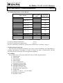
1
Do Žlábku 733, 514 01 Jilemnice
Subject: MTP (MTPAL) – Technical Documentation
Page 1 of 13
MTP (MTPAL) AIR HEATERS
TECHNICAL DOCUMENTATION
Table of Contents:
Page: 2
3
4
9
13
13
Warranty Certificate
Quality and Completeness Certificate (Product Test Sheet)
Technical Conditions
Assembly, Operating and Maintenance Instructions
List of Accessories and Spare Parts
List of Certified Repair Centres
Annex No.:
1 Certificate No. E - 00663-02-rev.1 (gaseous fuels)
or No. B-30-00664-02 (liquid fuels) – SZU Brno
2 Declaration of Conformity
3 Wiring Diagram
4 ESD3J Thermostat – User Manual
5 MTP (MTPAL) Air Heaters – Technical Data and Dimensions
6 MTP (MTPAL) Air Heaters – Loading and Transportation Instructions
Approved by:
Date: July 1, 2006
Do Žlábku 733,CZ- 514 01 Jilemnice
Subject: MTP (MTPAL) – Technical Documentation
Page 2 of 13
Warranty Certificate
The Manufacturer shall be liable for any defects of the Product which undisputedly occurred
during the Warranty Period as a result of defective design and/or manufacture.
The Manufacturer shall not be held liable for any defects if:
- the Product is changed or amended in any way by the Purchaser or any party working on
his behalf;
- the seals affixed on the Product are broken;
- the Product is damaged by applying too much force;
- the Product and any part thereof is not set up and/or connected according to the
Manufacturer’s instructions;
- the Product is situated in an environment not recommended by the Manufacturer in the
relevant documents; and
- the Purchaser does not follow the Technical Conditions provided by the Manufacturer.
Warranty Period:
Provided the conditions set forth herein (i.e. the Manufacturer’s instructions and
recommendations) are met, the Product shall have a Warranty Period of twenty four (24)
months, commencing on the day of delivery of the Product.
As another Warranty Condition, the Manufacturer hereby expressly reserves the right to
appoint a person to be present, at the expense of the Purchaser, during the start of operation
of the Product at the Purchaser’s premises.
Product:
AIR HEATER
Type:
MTPAL
Serial Number:
Date of Delivery of the Product (as affirmed by the Seller):
Go-Live Date (as affirmed by the Supplier):
___________________________________________________________________________
This Warranty Certificate is to be produced by the Purchaser with any claim; it has to be
supported by the Go-Live Certificate, duly validated by the person appointed for this purpose
by the Manufacturer, and the Burner Setup Certificate.
This Warranty Certificate is void unless produced
together with the Go-Live Certificate!
Do Žlábku 733,CZ- 514 01 Jilemnice
Subject: MTP (MTPAL) – Technical Documentation
Page 3 of 13
Quality and Completeness
Certificate
(Product Test Sheet)
The Manufacturer hereby attests and confirms that the Product specified hereinafter meets the
requirements of the applicable testing regulations, i.e. ………………………………………..
………………………………………………………………………………………………….
Product: AIR HEATER
Type: MTPAL
Serial Number: .........................................
Basic Technical Data
Nominal Heat Input:
................................................ kW
Nominal Heat Output:
................................................ kW
Nominal Airflow:
............................................... m3/h
External Air Pressure:
............................................... Pa
Nominal Electric Input:
............................................... kW
Weight:
............................................... kg
IP Degree of Protection
IP
Voltage:
3 x 400 V + N + PE 50 Hz
Electric Engine Used:
...............................................
V-Belt:
...............................................
Date:
OTK:
___________________________________________________________________________
Ing. Václav Šubrta
Manufacturing Director
Do Žlábku 733,CZ- 514 01 Jilemnice
Subject: MTP (MTPAL) – Technical Documentation
TECHNICAL
CONDITIONS
MTP (MTPAL) AIR HEATER
Page 4 of 13
Do Žlábku 733,CZ- 514 01 Jilemnice
Subject: MTP (MTPAL) – Technical Documentation
Page 5 of 13
1. Validity
These Technical Conditions cover the functional, design, testing and delivery
requirements of standard air heaters. Applying to horizontal and vertical heaters intended for
indoor and outdoor use, these Conditions are valid until declared invalid or replaced by a
newer version.
2. Usage
Irrespective of the heater and fuel used (natural gas, coal gas, propane butane, fuel oil or
light heating oils), air heaters are intended for:
a) heating of closed spaces
b) technological heating
c) ventilation (using non-heated fresh air)
3. MTP (MTPAL) – Function Description
Having separate air-conditioning and combustion circuits, the heater draws, via a fan, air
from the environment (floor) or a dedicated air duct. By drawing air from its environment,
the heater also improves local sanitary conditions. Flowing around the combustion chamber,
the air is heated and subsequently runs to the outlet section.
Burners are selected according to the fuel to be used. Combustion products are conducted
away through a duct attached to the waste outlet of the combustion chamber. The burner and
the waste-gas flue are not supplied by the Manufacturer.
4. Type Identifiers
Heaters have a specific type identifier with the following meaning:
MTP (MTPAL) – 25
Air Heater
Type Size (see Art.10)
5. Structural Description
The main casing of the heater consists of a frame made of individual sections allowing
easy coverage of the heater. Made of welded sheet metal, the combustion chamber is fixed to
the heater with bolts. Heater covers are equipped with internal heat insulation and shutters
enabling air to be drawn in. Below the combustion chamber, there is a fan with an electric
motor. The motor is fixed to the frame and fan to allow a V-belt to be stretched between the
pulleys of the motor and fan. The area of the motor and fan is covered by shutters allowing
heated air to be drawn in. To keep the air clean, there are filters installed in this section.
The burner is fixed on the front side of the heater, allowing fuel to be burned in the
combustion chamber. Combustion products are discharged through the waste outlet, typically
situated on the rear side of the heater, and conducted away through a duct attached to the
waste outlet. The heater is equipped with an electric control unit with switching, control and
safety circuits to enable fully automatic heating.
Typically, the control unit is installed on the front or lateral side of the heater, according to
the customer’s wish; however, the unit can also be installed as a stand-alone control (i.e. not
fixed to the heater). In the latter case, the control unit still forms an integral part of the heater
and is supplied separately (installation and connection to be done by the customer).
Do Žlábku 733,CZ- 514 01 Jilemnice
Subject: MTP (MTPAL) – Technical Documentation
Page 6 of 13
The heater is further equipped with a system draining combustion condensate from the
combustion chamber (a 1/2" pipe). The heater also includes a triple thermostat to ensure
smooth and safe operation (switches the fan on and off and limits the maximum temperature
of the heater)
6. Operating Conditions
Smooth and safe operation can be guaranteed only on the following conditions:
a) All parameters set forth by the manufacturer have to be observed, in particular:
- nominal heat input ( kW );
- nominal airflow ( m3/hour );
- air temperature ( for typical systems not more than 40 °C );
b) Working environment
In terms of working environment, there are two main heater types: indoor heaters and
outdoor heaters.
- Indoor systems equipped with IP 40 protection degree can be used in standard /
basic environments.
- Outdoor systems with IP 43 protection degree are intended for outdoor use; here, the
burner and thermostat are equipped with special shields protecting them from
atmospheric precipitations.
- Be sure to prevent outdoor systems from sucking in larger objects (such as tree
leaves).
c) Combustibles must not be stored in the vicinity of the heater – fire hazard !!!
7. Noise Level
As reported by SZU Brno, the mean value measured in the vicinity of a MTP 65 heater
was Ldl = 74,2 dB (A), thus not reaching the maximum allowed limit of 85 dB (A).
8. Engineering Supervision and Inspection
During manufacture, the Manufacturer is responsible for engineering supervision and
inspection and its acceptance.
Besides, the Manufacturer has reserved the right to appoint a person to be present during
the start of operation of the heater.
Subsequent supervision is carried out by Strojírenský zkušební ústav Brno (SZU Brno)
according to EC Directive No. 2009/142/EC (as transposed into Czech national law in
government regulation No. 22/2003 Coll.), Annex II.2, Art. 2.3. Supervision takes place in
the form of random inspections of the heaters according to the EC Certificate.
9. Documentation
Every product is supplied with a set of documents required for its smooth and safe
operation (i.e. this technical documentation).
Do Žlábku 733,CZ- 514 01 Jilemnice
Subject: MTP (MTPAL) – Technical Documentation
Page 7 of 13
10. Technical Parameters of the Heaters
Type / Model
MTP 25
MTP 37
MTP 50
MTP 65
MTP 85
MTP 100
MTP 125
MTP 150
MTP 175
MTP 225
MTP 300
MTP 350
MTP 400
MTP 525
MTP 650
MTP 850
MTP 1000
Note:
MTPAL 50
MTPAL 80
MTPAL 150
MTPAL 200
MTPAL 300
MTPAL 500
MTPAL 700
MTPAL 900
Heat Output
(kW)
29
45
60
75
100
120
150
175
200
260
350
400
465
600
750
990
1,160
Max Heat
Output (kW)
50
80
140
200
275
460
700
900
MTPAL ....................commercial branding
Loss due to thermal transmission
2.0 %
Loss due to combustion products heat
10.9 %
For more information consult the “Quality and Completeness Certificate” (page 3).
11. Materials and Surfacing
The materials and surface treatment used ensure required durability and adaptability in
working environments according to Article 6 hereof. In terms of interference and the
prevention thereof, the heater meets all applicable standards.
12. Labelling
Every heater bears a non-removable label with the following information:
a) Manufacturer
b) Product ID
c) Type identifier
d) Serial number
e) Year of manufacture
f) Nominal heat input (kW)
g) Nominal heat output (kW)
h) Nominal airflow (m3/h)
i) External air pressure (Pa)
j) Nominal electric input (kW)
k) Weight (kg)
l) Voltage ( 3 x 400 V + N + PE 50Hz )
m) IE degree of protection
n) Intended country
Do Žlábku 733,CZ- 514 01 Jilemnice
Subject: MTP (MTPAL) – Technical Documentation
Page 8 of 13
Furthermore, there is a label on all exchanger parts with the following text:
“This heater has to be installed according to the instructions of the Manufacturer and
can be used in well ventilated areas only. Read instructions before installation and use!”
13. Tests
Type Tests
Type tests are performed by: Strojírenský zkušební ústav Brno s.p., zkušebna 202,
Hudcova 56b, 621 00 Brno, the Czech Republic.
Production Tests
Production tests of every exchanger part are performed by the manufacturer in his
production plant: JINOVA s.r.o., Do Žlábku 733, Jilemnice, the Czech Republic.
Production tests comprise of the following tests and inspections:
- weld tests of the casing
- weld tests of the exchanger
- inspection of external interface dimensions
- surfacing inspection
- inspection of the device and its accessories in terms of completeness
- wiring inspection
- impressed voltage test
- insulation inspection
- function tests
For further information consult the “Product Test Sheet”.
14. Packaging, Transportation and Storage
- If requested by the customer, supplied heaters are wrapped in fixation foil to reduce
possible surface damage and mounted on wooden bases or pallets.
- All persons taking part in the transportation and loading of the heaters are advised to
proceed with caution. Handling allowed only by means of the pallet, lower frame
(between the wooden bases) or welded loops. Where there are two loops, both have to
be used; in such cases, using one loop only is strictly prohibited! Packages must not
be subjected to atmospheric exposure, continuous humidity and shocks.
- Heaters have to be stored in well ventilated rooms with no corrosive vapours or active
gases, or outdoors under a shelter protecting the heater from any atmospheric
precipitations.
Do Žlábku 733,CZ- 514 01 Jilemnice
Subject: MTP (MTPAL) – Technical Documentation
Page 9 of 13
ASSEMBLY INSTRUCTIONS
Handling
The heater will be delivered freely or, at the customer’s request, on a wooden pallet
wrapped in a fixation foil. While unloading, in particular using a forklift, the heater has to
stand on the palette by all means.
The fork of the forklift used has to be long enough to lead under the whole palette. Using
short forks will inevitably result in damage to the heater. It is also possible to use a crane to
unload the heater. In such a case, the heater includes one or two (depending on heater type)
loops (at the tube plate of the combustion chamber) or handling holes in the under-frame
(handling using bars). If there are two loops on the device, both have to be used; in such
cases, using one loop only is strictly prohibited!!!
Positioning
! The heater has to be positioned on a level and sufficiently solid ground or frame. In order
to allow condensed fluids to flow off, the heater has to be positioned horizontally (minor
downward grade helping the outflow is acceptable). The heater has to be positioned in a way
to allow the combustion chamber to be replaced and the tube zone to be cleaned. In other
words, there has to be a free space in front of the front (burner) side of the heater at least
equal to its size (“length x width x height”). The cover of the tube plate of the exchanger
chamber (opposite the chimney) has to be kept free to allow easy removal when cleaning the
tube plate.
! The heater has to be positioned in a way allowing the V-belts to be put in place and/or
removed (upon removing the covers) and the tube plate to be cleaned.
! Outdoor heaters installed on a roof have to be equipped with a lightning rod.
Safe Distances
True distance between the heater and any combustible material must comply with all
applicable standards, i.e. must not be smaller than 200 mm.
If it is not possible to meet this condition, a protective screen has to be used. The screen
has to be at least 3 mm thick and made of a material of flammability class A or B. The screen
has to be in a fixed position between the heater and the protected substance, 30 mm (±5 mm)
from the protected material. The screen has to stretch to the nearest wall (ceiling) made of a
non-combustible material, but at least 300 mm beyond the upper and 150 mm beyond the
lateral edges of the protected material. When a protective screen is used, the minimum
distance allowed can be halved.
When installing a gas heater on a floor made of a combustible material, a non-conducting
insulation pad has to be used. The pad has to be resistant to mechanical load and made of a
Do Žlábku 733,CZ- 514 01 Jilemnice
Subject: MTP (MTPAL) – Technical Documentation
Page 10 of 13
material of flammability class A or B. In terms of ground plan, the pad must not be smaller
than the heater; moreover, it has to be at least 5 mm thick.
!
Do not store combustibles in the vicinity of the heater – possible fire hazard!
Objects which can hinder air circulation must not be placed closer than 1 m to the heater.
Connection to Air Ducts
In stand-alone operation (i.e. not connected to air ducts), the air distributor in the outlet
section is attached directly to the frame of the heater. The distributor is bolted to the heater
and then, typically, it is fitted with double-row diffusers (supplied with the distributor). When
connecting the heater to intake or outlet air ducts, the initial duct sections can be bolted
directly to the frame; alternatively, a silent-block can be used.
Connection to Smoke Flue
The smoke flue has to be installed by a specialised company and according to all
applicable regulations.
Note: Every heater equipped with a high-pressure gas boiler has to be connected with a
separate smoke flue to a separate vent stack.
If the heater includes a condensed fluid receptacle (20 – 30 l), it is intended both for
combustion chamber condensate (1/2" discharge pipe) and chimney-bottom condensate.
! Note: Irrespective of their type, the operation of any MTP heater requires proper drainage
of flue-gas condensate.
Installing the Burner
Typically, heaters are fitted with pressure burners (single-stage, double-stage or smooth
fuel input regulation). Burners are not a part of the heater delivery. Fuel intake has to be
installed by a specialised company and has to meet all applicable regulations according to the
fuel and/or burner type used.
The installation and setup of the burner has to be done by an engineer appointed by the
manufacturer of the burner. After the burner has been duly inspected and set up, a setup
certificate is issued; at this point, the heater is ready for final inspection and to go live. As
already given herein, the manufacturer of the heater reserves the right to have one of his
engineers present during the go-live procedure at the expense of the purchaser. Not meeting
the following requirement may result in the warranty becoming void.
Typically, heaters are fitted with flanges and seals into which the burner is mounted using
bolts. In outdoor heaters, an appropriate cover has to be fitted above the burner.
Before installation always check the compatibility of local conditions relevant for the
operation of the heater, i.e. fuel intake, fuel properties, fuel pressure and heater setup.
Do Žlábku 733,CZ- 514 01 Jilemnice
Subject: MTP (MTPAL) – Technical Documentation
Page 11 of 13
Wiring
All electrical services have to be rendered by professionals. After the services have been
completed, a thorough inspection is required. When connecting the ESD3J thermostat,
Weishaupt burner and measurement and control circuits, follow the recommended wiring
diagram attached hereto (drawing No. 3-JH-2001C)
!
After connecting the fan, be sure to check the direction of its rotation!
The heater is equipped with an earthing connector.
!
Under any circumstances, the
clamp of the triple thermostat has to be connected to
the PE conductor in order to make sure that the thermostat sensor is not influenced by
possible induced voltage.
OPERATING INSTRUCTIONS
When installing and operating heaters burning natural gas, coal gas, propane butane, fuel
oil or light heating oils, the following rules have to be observed.
Every heater has in its outlet section a triple thermostat ensuring smooth and safe
operation. This thermostat is not intended for controlling required temperature.
T1 – Safety Thermostat – shuts down the burner by cutting off its power supply. After a
safety shutdown, the burner cannot be engaged again automatically unless a specific
button has been pressed on the thermostat first. Before the thermostat can be
unblocked again, the temperature at the T1 thermostat has to drop below the
specified threshold. Before enabling the heater again, be sure to find out and remedy
the cause of the overheat.
The thermostat used allows the T1 safety thermostat to be reset remotely (e.g. by
means of a control panel button), this can be helpful in case of poorly accessible
exchanger sections (e.g. suspended sections).
When power supply is cut off while the burner is engaged, temperature will
increase because the fan cannot draw away the heat accumulating in the exchanger
chamber. After the temperature exceeds the preset threshold, T1 will cut off the
power supply of the burner, thus disengaging it. Once power supply is restored, the
thermostat will be reset automatically, provided that the temperature measured here
dropped below the set threshold in the meanwhile. In case of short power failures
(i.e. when the temperature still exceeds the limit when power supply is restored), it is
necessary to wait for the chamber to cool down; subsequently, the thermostat can be
reset manually by pressing the appropriate button.
T2 – Operational Thermostat – turns the burner off after the temperature exceeds the
relevant threshold and turns it on when it drops again.
T3 – Fan Thermostat – turns on the fan once the temperature exceeds the relevant threshold
and switches the fan on to cool down the chamber after the burner has been shut
down.
Do Žlábku 733,CZ- 514 01 Jilemnice
Subject: MTP (MTPAL) – Technical Documentation
!
Page 12 of 13
Attention
The main switch can be turned off only after the fan stops completely. When not using the
heater for a longer period of time, be sure to shut off fuel intake.
Once properly set up and commissioned by professionals, the device and its parameters
cannot be altered in order to ensure smooth and safe operation.
For maximum safety, it is recommended to have the heater checked at least once in a year by
the manufacturer or an approved service centre!
MAINTENANCE INSTRUCTIONS
The heater has to be maintained after every scheduled shut-down. Maintenance and all
related actions have to take place in accordance with the instructions set forth herein.
Maintenance Works:
!
!
!
!
a) Inspect the tension of the V-belt and its wear and tear (as needed).
b) Check whether the bolts of the burner plate and tube plate lid are tight; first check
to take place after one month of operation, subsequent checks before every heating
period.
c) Perform regular checks of intake filters (at least once a month); if needed, clean or
replace filter fabric. The speed of filter clogging depends on the purity of suction air.
Any dirt substantially decreases the volume of air supplied by the heater, thus
increasing exchanger chamber temperature.
d) Have the burner checked and set up by a certified engineer at least once in a year
(preferably before the start of the heating season). Burner setup is possible only while
the heater is operational.
e) Clean the tube plate at least once in a year (or as needed).
In case of fuel oil and light heating oils, clean the tube plate every time there is a
decrease in heating efficacy (as needed, possibly even once a month). Once cleaning
is finished, be sure to tighten the bolts of the tube plate lid properly and, if needed,
replace washers. (Check tightness again after a month of operation!)
Defects
a) Electric defects have to be remedied according to the wiring diagram supplied with
every heater.
b) Overheating
- make sure that intake and outlet areas are not clogged (ducts, etc...)
- check filtration fabric and filter
Do Žlábku 733,CZ- 514 01 Jilemnice
Subject: MTP (MTPAL) – Technical Documentation
Page 13 of 13
- if filters appear to be in good condition, consult the defect with the
manufacturer.
c) Combustion products detected in heated area or increased oxygen content discovered in
combustion products
- make sure that the bolts of the tube plate lid and burner flange are tight.
- change the washers in the tube plate lid and/or burner flange.
- make sure there is no hole in the combustion chamber.
LIST OF ACCESSORIES AND SPARE PARTS
Accessories supplied with the heater have to be ordered separately.
- filtration frame
- belts
- filter
The above accessories can be ordered at any time at the manufacturer’s plant.
No spare parts are supplied with the heater. Spare parts for warranty repairs are available
at the manufacturing plant; all warranty repairs (except for burner defects) can be performed
by the manufacturer’s engineers.
Post-warranty repairs take place at the customer’s expense. The required spare parts can be
obtained from the manufacturer.
The warranty period does not apply to V-belts (their type and size is specified in the
Quality and Completeness Certificate) and filtering fabrics.
LIST OF CERTIFIED REPAIR CENTRES
Warranty and post-warranty repair services of MTP heaters are provided by the
manufacturer:
JINOVA s.r.o. , Do Žlábku 733, 514 01 Jilemnice, the Czech Republic
tel.: +420 481 541 518, +420 481 549 351, fax.: +420 481 544 184, +420 481 543 163