1
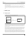
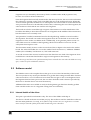
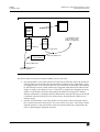
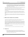
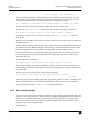
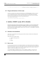
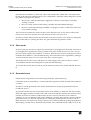
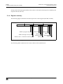
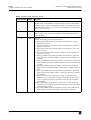
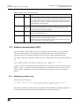
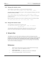
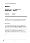
European Laboratory for Particle Physics
Laboratoire Européen pour la Physique des Particules
CH-1211 Genève 23 - Suisse
FEDKIT
FEDKIT user’s manual and
programer’s manual
Document Version:
Document Date:
Document Status:
Document Author:
beta 0.4a
29 May 2002
Work version / subject to additions
Eric Cano
Abstract
This document introduces the use of the FED receiver and sender boards. Those boards and
the toolkit are designed by the CMS data acquisition group for all the detector front end
developers to provide read-out functionality from the Slink-64 connector on the FED.
1 Introduction
In the CMS data acquisition, the event builder will retrieve event fragments from each
sub-detector’s front end driver (FED) through a normalised connector and protocol. This
protocol was defined by the Readout Unit Working Group (RUWG) [1]. This protocol is
specified in the S-link 64 [2] protocol for the data transfer protocol and by the RUWG for the
format of the event fragments.
The CMS DAQ group is working on the design of boards an link that will take the data from
the FED’s Slink connector and send it through a cable to the receiving machine. The receiver
board is based on the Generic III board (all purpose board based on an FPGA).
The Generic III receiver board is a PCI 64 bit/66 MHz board that will sit on the receiver
machine (PC). The sender board is also based on the GIII. Both boards communicate thanks to
PMC format daughter boards.
A few definitions to be clear with words: the CMS apparatus generates events, which are
collected from the many FEDs (front end drivers) by the DAQ. The FEDkit implements this
link from the FED to the DAQ. This document uses “fragment” to designate what comes out
of the FED. On a more technical point of view, the FEDkit uses memory blocks to store the
event fragments. So, from the fedkit’s point of view: a event fragment, or fragment, is made
of one or more blocks.
Work version / subject to additions
page 1
FEDKIT
2 FEDKIT model
FEDKIT user’s manual and programer’s manual
Version/Issue: beta 0.4a/1
The blocks correspond to physical memory locations. The receiver board send the data to
those locations by a DMA.
Finally, the fedkit internally uses several FIFOs. Those FIFOs allow communication between
the software and the hardware board. (this is detailed in Section 2, "FEDKIT model").
This document is still preliminary. Some informations are not known yet and are therefore printed in
italic.
2 FEDKIT model
2.1 Hardware model
The FED kit is based on the link setup (two boards and cable). The receiver board sends the
received data to the host PC’s memory through the PCI bus.
FED (sub-detector
dependant)
Slink connector
Link
S-link receiver board
(Generic III)
Figure 1 FED kit layout
The FED gets the L1 (hardware) triggers and sends automatically the event fragment to the
S-link receiver. The model is a push model, but the S-link receiver throttles the data flow so
that it won’t overflow.
The receiver board works with DMA. It sends the received events through a DMA to memory
blocks provided by the host. After DMAing an event fragment to host memory, the s-link
receiver board simply sends the word count for the received event into a software FIFO (in
memory, the word count FIFO). This scheme is developed in detail in Section 3.
When the receiver board starves on data blocks, it simply uses the back pressure feature of
Slink. No overflow is therefore possible on the board (but this can create an overflow on the
FED, which in turn is able to throttle the trigger rate). On the other hand, the board can ask for
additional data blocks thanks to interrupts. This scheme was chosen to provide a arbitrary
page 2
Work version / subject to additions
FEDKIT
2 FEDKIT model
FEDKIT user’s manual and programer’s manual
Version/Issue: beta 0.4a/1
fragment size (it is limited by the memory blocks available and to 4GB (in practice less)
because we work on 32 bits architecture.
Once the fragment has been fully transferred to the memory blocks, the receiver board notifies
the software by posting on the word count FIFO the size of the transferred event. When this
word count fifo gets full, the data flow is interrupted. The software knows which data blocks
were passed to the receiver board and in which order, so knowing the size of the fragment, the
software knows which blocks are used for each fragment.
The board can also be reseted through a register. This function is used at initialisation. The
board has the ability to abort the transmission of a fragment in the middle of the transmission,
but this feature is not currently used.
An optional PCI sender/transmitter board is developed along with the receiver board for
development. This board can send event fragments from PCI to the link. It can receive the
fragments in slave mode or in DMA mode. Additionally, it can generate pattern events. As
some FEDs won’t be available at the beginning, this board could be of some use for the
subsystems developers as well.
This document mainly focuses on the receiver board, but a chapter is devoted to the sender
board. The API of the fedkit also covers the sender board. See Section 5, "Addition: FEDKIT
sender (PCI to Slink64)" and Section 3.4, "Self send extension".
A second version of the receiver board receives the data from two links. The fragments from
each FED are concatenated and make a single event fragment in the memory.
Later this merger will have some synchronisation features to handle the cases when the FEDs are out of
sync, or when on of the 2 FEDs die (timeout).
2.2 Software model
The FED kit comes with complete driver that gives access to the functionality of the board.
The user just has to rely on the provided driver to get the data coming from the FED. The basic
software model is a set of C functions from which the user gets a new event fragment. Once
the fragment data has been processed, the user frees the buffer with a function provided by
the driver so that the driver can reuse the memory.
Additional functions are available to analyse the fragments (get data from header, get data
from one FED in the case of a fragment coming from several FEDs).
2.2.1 Internal details of the driver
This part is provided for information only. The user of the fedkit could skip it.
The driver is based on the i2ocore toolkit (see [3]). This toolkit is useful to make device drivers
that are multi-platform. Currently, as the fedkit is only used in Linux, we might move to a Linux
native interface (instead of Xdaq-shell) which would bring more robustness.
Work version / subject to additions
page 3
FEDKIT
2 FEDKIT model
FEDKIT user’s manual and programer’s manual
Version/Issue: beta 0.4a/1
Receiver board
2: DMA data
Free data
blocks
FIFO
Data blocks
Driven by interrupt
Software
Software
FIFO
FIFO for
in shared
Word counts
memory
(free data blocks)
3: word count
pointers in
board FIFO
5: Get data blocks
and word count
makes a fragment
4: block addresses
1: block addresses
Free fragments or
allocate blocks
Figure 2 General layout of driver
The driver holds several lists inside the fedkit_receiver structure:
page 4
•
free pointer FIFO: a list of the pointers to free blocks not already sent to the board in a
software FIFO (as the board’s free pointer FIFO is limited in size). This FIFO is store
in a bigphys block, as it is filled by the user space functions of the fedkit, and emptied
by the interrupt service routine (interrupt is triggered when the board’s FIFO is half
empty or empty). This FIFO uses (n+1) * 4 bytes in a single block of bigphys memory,
where n is the number of blocks allocated by the fedkit at startup (this is 1000 by
default). This FIFO is completely filled at initialisation, then the interrupt of the board
is enabled, and the interrupt service routine start to feed the board’s FIFO (as it is
initially empty.
•
pointers in board FIFO: a list of the pointers to free blocks sent to the board. This is
just a chained structure in the driver. It is only used in user space. This chain is filled
with the pointers to the same blocks as the free pointer FIFO, but is emptied by the
process generating the fragment structure.
Work version / subject to additions
FEDKIT
3 FED receiver hardware documentation
•
FEDKIT user’s manual and programer’s manual
Version/Issue: beta 0.4a/1
word count FIFO: this FIFO is located in the host’s memory. It is filled by the board
itself, and emptied by the user space functions. When a word count is poped from
this FIFO, the corresponding number of block addresses is poped from the pointers
in board FIFO. This one is also stored in a bigphys block, and has a fixed size (it uses
2 blocks of 4kB on a x86 architecture.
All the bigphys blocks used here are actually Dbuffs (dma buffers of xdaq-shell, defined in the
i2ocore package [3]) and accessible from user space, kernel space and PCI bus.
The interrupt is triggered when the hardware ‘free block’ FIFO is half empty or empty. The
interrupt service routine then feed this FIFO with free block addresses from the pointers to
free blocks FIFO.
Now when a fragment comes from the FED, but the board has no data blocks available, the
software can send the “abort fragment” command. The board will then send the partial
fragment to the word count FIFO, with a special flag. This feature is currently not used in the
fedkit.
With this scheme, we can allocate an arbitrary number of blocks, limited only by the size of
the bigphys memory. The data blocks themselves are also allocated from the bigphys memory
itself.
3 FED receiver hardware documentation
The FED receiver board implements mainly a hardware FIFO to hold the free data blocks
addresses and the support for a software FIFO in which word counts are sent.
Whenever it receives data from the Slink, the board DMAs data to the first available data
block in its FIFO and updates an internal word count. If data spans over one block, the DMA
engine goes on on the following block. When the free data block FIFO is empty, the process
waits for a free data block to become available on the FIFO to go on. If the software driver is
unable to provide free data blocks to the board, a special command (abort event) is used by
the driver software.
As a separate process, the boards asks for more free data blocks when the FIFO is half empty
and empty by generating interrupts.
The FED receiver board is a PCI board with vendor ID 0xECD6 and device ID 0xFD05.
3.1 Register list
•
Block size register: write only (block size in bytes, has to be 64-bit aligned)
•
DATA block FIFO (write only): PCI address of each block. The FIFO is 1024 addresses
deep, and the driver implementor has to synchronise the sending of words with the
FIFO half empty and FIFO empty interrupts
Work version / subject to additions
page 5
FEDKIT
3 FED receiver hardware documentation
•
•
FEDKIT user’s manual and programer’s manual
Version/Issue: beta 0.4a/1
Software FIFO registers (word counts - in bytes. Byte counts actually) see Section 3.3.
•
FIFO base address. Points to the PCI address of a 1024 word (4096 bytes
zone)
•
Read offset register (write only). Point to the next location to be read (not
read yet).
•
Write offset register address (where the board pushes the write offset
pointer). Points to the first free location.
Control and status register (CSR): read status write control.
•
•
The 8 LSBs indicate interrupt status. Interrupts are stateless, that is the only
way to clear an interrupt is to remove the condition that triggers the
interrupt. FIFO half empty is cleared by filling the FIFO. Interrupts can also
be masked or enabled through the bits 8 to 15.
•
CSR[0]: reads 0 if FIFO is not empty. 1 if empty. An interrupt is
triggered if CSR[9] is set to 1. CSR[1] is a read only bit.
•
CSR[1]: reads 0 if FIFO is more than half full. 1 if half empty. An
interrupt is triggered if CSR[9] is set to 1. CSR[1] is a read only bit.
•
CSR[8]: enables the FIFO empty interrupt. This bit is readable and
writable.
•
CSR[9]: enables the FIFO half empty interrupt. This bit is readable
and writable.
•
If not masked, triggers an interrupt. Writing 0 masks the interrupt
(default). Writing 1 enables the interrupt.
The 16 most significant bits correspond to functions.
•
CSR[16] writing 1 triggers an abort event. Reads 1 if abort event is
still in progress or 0 on the other case.
•
CSR[17] writing 1 start a “clear board” (software reset). Reads 1 if
reset still in progress, 0 otherwise.
•
CSR[18] simple read/write bit. writing 1 enables the link (this
includes a synchronisation operation over the link). Writing 0
disables the link. Reading the bit gives the state of the link
(enabled/disabled)
This mapping is summarised in the following figure:
page 6
Work version / subject to additions
FEDKIT
3 FED receiver hardware documentation
31
FEDKIT user’s manual and programer’s manual
Version/Issue: beta 0.4a/1
23
15
parameter FIFO full
(self send version)
Link enable
Software reset
7
0
fifo empty
interrupt enable
fifo half empty
interrupt enable
Abort event
fifo half empty indicator
fifo empty indicator
Figure 3 Bit mapping in the control word
3.2 Registers offsets
Table 1 Registers description
Mnemonics
Register description
Offset from base address 0
BKSZ
Block size (in bytes, must be
64 bits aligned)
80h
WCFADDR
Word count FIFO address
84h
WCFR
Word count FIFO read offset
(in words) see Section 3.3
08h
WCFWADDR
Word count FIFO: address of
the write register address in
memory
88h
FRBKFIFO
Free block FIFO
04h
CSR
Control and status register
00h
3.3 Software FIFO protocol
The offset variables (read and write point to the next word to be written (or read)). Every time
there is a write or read, the corresponding variable is incremented. Those variable are eleven
bit variables. The 10 least significantly bits (bits [9..0])contain the number of the block to be
next read or written. The additional MSB (bit 10) is added to the number. When a write is
done, this variable is increased by one (and wrap to 0 after 2048 increases).
Work version / subject to additions
page 7
FEDKIT
4 FED software driver
FEDKIT user’s manual and programer’s manual
Version/Issue: beta 0.4a/1
This trick allows us to know if the FIFO is completely empty or completely full when
write[9..0] == read[9..0]
If write [10] == read[10] (and write[9..0] == read[9..0]), the FIFO is empty (we can write, but
not read) the other way round, if write[10]!=read[10] (and write[9..0] == read[9..0]), the FIFO
is full (we can’t write, but we can read). The board and the driver keep a copy of each value,
so FIFO can work. The software has to poll the FIFO to know if it’s empty or not.
3.4 Self send extension
A special version of the board was developed for software design. Instead of requiring a
sender and receiver setup, this special receiver board has a generator interface on another PCI
base address. This allows simpler hardware setups for developing receiver software setups. A
special function supporting this feature is included in the fedkit receiver API. (see
Section 4.2.7, "Self send functionality")
In a possible extension the board could generate an interrupt when the word count FIFO is empty. The
driver would then rely on interrupt and not on polling to know when an event is available.
Another additional extension could be to have the receiver board writing the word count plus a pointer
address (last or first pointer, this doesn’t matter) for each event in order for the software to detect if
software FIFO and hardware FIFO are still in sync (they should be all the time, so this is just for
additional robustness). This would be hidden from the user by the fedkit software).
4 FED software driver
4.1 Getting and installing the software
The latest release of the software, the latest documentation, etc... can be found on the fedkit
web page: http://cern.ch/cano/fedkit.
4.1.1 Software requirements (kernel patch)
The FEDKIT needs the bigphysarea patch to be installed. The version of this patch matching
the Linux kernel you are using can be found on the page:
http://www.polyware.nl/~middelink/En/hol-v41.html
The 2.4.16 kernel which we recommended in the previous versions of this documentation
turned out to be buggy. We found out that the kernel from the official CERN RedHat 7.2.1 was
OK. this kernel also has the advantage to contain the bigphys patch already.
This kernel sources can be retrieved from AFS:
page 8
Work version / subject to additions
FEDKIT
4 FED software driver
FEDKIT user’s manual and programer’s manual
Version/Issue: beta 0.4a/1
/afs/cern.ch/project/linux/dev/kernel/2.4-current/build-current
Then /etc/lilo.conf just has to be updated to boot from this image. Also add as a kernel
parameter the size of the memory to be reserved for bigphys:
append="bigphysarea=16384"
4.1.2 Retrieve the sources from CVS and compile
The sources are stored in a CVS repository. They can be retrieved from the CMS CVS server
the following way:
# cvs -d :pserver:[email protected]:/cvs_server/repositories/TriDAS login
(password for anonymous checkout is "98passwd")
# cvs -d :pserver:[email protected]:/cvs_server/repositories/TriDAS co\
-P -r fedkit_v_1_14 TriDAS/daq/itools TriDAS/Auxiliary/i2o
The tag (here fedkit_v_1_14) might change over time. It is not recommended to get the head
as you could get development versions. The various versions of the software and the various
tags can be found on the web page of the fedkit [5] as well as all the revisions of this
document.
The fedkit library is compiled by doing:
#make fedkit
in the TriDAS/daq/itools directory. This will create a package subdirectory containing all the
libraries and the include files.
4.1.3 Install and link the software library, load the kernel modules
To compile a program using fedkit, the header file “fedkit.h” has to be included, and the final
executable has to be linked with libfedkit.a and libxdaq-shell.a.
The required includes are in the directories
TriDAS/daq/itools/packages/fedkit/include
TriDAS/daq/itools/packages/i2o/include
TriDAS/daq/itools/packages/xdaq-shell/include
and libraries are:
TriDAS/itools/packages/fedkit/libfedkit.a
TriDAS/itools/packages/xdaq-shell/libxdaq-shell.a
To run the software, 2 special files have to be created:
crw-rw-rwcrw-rw-rw-
1 root
1 root
root
root
124,
124,
0 Dec 14 15:03 /dev/xdaq-shell
1 Nov 22 11:47 /dev/xdaq-shell-pmap
The following commands create those files (as root, or using sudo):
Work version / subject to additions
page 9
FEDKIT
4 FED software driver
/bin/mknod
/bin/chmod
/bin/mknod
/bin/chmod
FEDKIT user’s manual and programer’s manual
Version/Issue: beta 0.4a/1
/dev/xdaq-shell c 124 0
a+rw /dev/xdaq-shell
/dev/xdaq-shell-pmap c 124 1
a+rw /dev/xdaq-shell-pmap
or the Makefile can be used (as root, or using sudo):
make device-files
Then before running the software, the kernel modules have to be loaded (as root, or using
sudo):
/sbin/insmod packages/i2o/i2ocore.o
/sbin/insmod packages/xdaq-shell/xdaq-shell.o
/sbin/insmod packages/fedkit/fedkit_kernel.o
They can also be loaded through the main Makefile (as root, or using sudo):
make load-fedkit
4.1.4 Example program
An example program is provided with the library. The file is
packages/fedkit/fedkit-example.c. It can be compiled by executing the following line
from the TriDAS/itools directory:
gcc packages/fedkit/fedkit-example.c -o packages/fedkit/fedkit-example \
-I packages/fedkit/include -I packages/xdaq-shell/include \
-I packages/i2o/include -D BIG_ENDIAN__ \
packages/fedkit/libfedkit.a packages/xdaq-shell/libxdaq-shell.a
4.2 API (programmer’s manual)
4.2.1 Initialisation functions
The first task of the user is to connect with a FED receiver board (fedkit_open). The
software can handle several boards in the same system. The software keeps track of each
board through a descriptor (struct fed_receiver) provided by the
open_fed_receiver function.
struct fedkit_receiver * fedkit_open (int index, int *status);
This function returns NULL in case of failure (board not found). The reason for the failure is
then coded into the status integer. If the user provides a NULL pointer in this place (meaning
“don’t care”) no error code will be available. This function can be used to scan for all the
receivers present in the system, testing from index 0 onward. When the user reaches an index
number unavailable, he know he found all the boards.
The user can then set the required parameters for the board. The parameters are:
page 10
Work version / subject to additions
FEDKIT
4 FED software driver
FEDKIT user’s manual and programer’s manual
Version/Issue: beta 0.4a/1
1.
Block size (the default size is TBD). For better efficiency, the block size should be a
multiple of the architecture’s page size (4kbyte on Intel). This size has to be 64 bits
aligned.
2.
The number of blocks the FEDKIT should allocate. In this version, all the blocks have
to be allocated at the beginning. This step is required.
3.
Header reserved size in bytes (the default is 0). The header size has to be aligned on a
64 bit boundary because of the DMA (64 bit DMA).
4.
A footer size could be added in the future with the same alignment requirements.
The ‘set’ function return positive or null parameter value, or a negative number on error
(error codes are TBD). The ‘get parameter’ functions return positive or zero parameter value
on success and negative error code on failure.
Functions prototypes are:
int fedkit_set_block_size (struct fedkit_receiver *receiver, int block_size);
int fedkit_get_block_size (struct fedkit_receiver *receiver);
int fedkit_set_block_number (struct fedkit_receiver *receiver,
int block_number);
int fedkit_get_block_number (struct fedkit_receiver *receiver);
int fedkit_set_header_size (struct fedkit_receiver *receiver, int header_size);
int fedkit_get_header_size (struct fedkit_receiver *receiver);
Once those parameters have been set, the driver has to be started. When the board has been
started, no parameter can be changed. (Some blocks are already in the FIFO of the board). The
start function returns 0 on success or negative error code on failure.
int fedkit_start (struct fedkit_receiver *receiver);
Once the receiver board has been started, it is ready for reception (the driver automatically
allocates memory blocks and feeds them to the board).
4.2.2 Fragment handling functions
To get the received event fragments, the user just has to get the received events, and to release
them after processing. The event metadata (pointers to blocks, possibly event ID and various
parameters) is stored in the fedkit_event structure. The first step is to get a fragment:
struct fedkit_fragment * fedkit_frag_get (struct fedkit_receiver * receiver,
int *status);
The ‘get fragment’ function return NULL on failure. In this case, the error reason is encoded in
the status integer (if pointer was not NULL, which is a valid entry meaning “don’t care”). The
reason can be “no event available”.
Several informations about the fragment can be extracted from the structure. The user can
query the number of blocks, the block size (which can be different from receiver to receiver),
the header size, and the size of the fragment. As in previous cases, getting a negative value
means an error condition.
int fedkit_frag_size (struct fedkit_fragment *fragment);
Work version / subject to additions
page 11
FEDKIT
4 FED software driver
FEDKIT user’s manual and programer’s manual
Version/Issue: beta 0.4a/1
int fedkit_frag_header_size (struct fedkit_fragment *fragment);
int fedkit_frag_block_size (struct fedkit_fragment *fragment);
int fedkit_frag_block_number (struct fedkit_fragment *fragment);
Everything is quite self explanatory, beside the fragment size, which is the size of the payload
only (the sizes of the headers are not included).
Once the fragment object is acquired, the user can access directly the blocks from the payload.
The pointer is a void *, pointing to the start of each block (hence start of the header) and the
user has to cast it to the desired structure or data type.
The blocks can be accessed through the function fedkit_frag_block:
void * fedkit_frag_block (struct fedkit_fragment *, int number);
Finally, once the fragment has been processed, the memory can be returned to the driver:
void fedkit_frag_release (struct fedkit_fragment *);
The memory for this fragment will be recycled into the board.
4.2.3 Fragment analysis functions
In order to be able to analyse easily fragment coming from the fedkit, and especially from the
merge version (2 fragments from 2 FEDs a concatenated in a single fragment by the board).
Those functions analyse the structure of the fragment. Specifically, the RUWG defined a field
on the trainer word of the FED payload that contains the size of the fragment. This field is
used to recover all the FED fragments in the fedkit fragment (in the case of the merge). Those
functions make some sanity checks on the fragment, and fail if the fragment structure is not
right.
The functions are the following:
int fedkit_frag_get_FED_number (struct fedkit_fragment * fragment);
this function returns the number of FED fragments in the fragment (this is useful in the case of
the merge, or negative (-error) if there was a problem.
void * fedkit_frag_get_FED_trailer (struct fedkit_fragment * fragment,
int FED_index);
This function returns a pointer to the trailer word of the given FED fragment, or NULL in case
of failure.
void * fedkit_frag_get_FED_word (struct fedkit_fragment * fragment,
int FED_index, int index);
This function returns a pointer to a given word in the FED fragment, or NULL in case of
failure.
U32 fedkit_frag_get_FED_word_pci (struct fedkit_fragment * fragment,
int FED_index, int index);
This function returns the PCI address of a given word in the FED fragment, or 0 in case of
failure. This function was mainly useful in the process of debugging the FEDKIT.
page 12
Work version / subject to additions
FEDKIT
4 FED software driver
FEDKIT user’s manual and programer’s manual
Version/Issue: beta 0.4a/1
int fedkit_frag_get_FED_trigger (struct fedkit_fragment * fragment,
int FED_index);
This function extracts the positive trigger number (LV1_ID) from the FED fragment. Returns
negative error in case of failure.
int fedkit_frag_get_FED_wc (struct fedkit_fragment * fragment, int FED_index);
This function extracts the positive word count from the FED fragment. Returns negative error
in case of failure.
4.2.4 Cleanup
As a last action, the board has to be released by the drivers, which will release all the resources
used:
void fedkit_close (struct fedkit_receiver *);
This function can be called anytime.
4.2.5 Suspending/restarting the receiver
The following functions are mainly useful to suspend the receiver so that a list of the blocks
internally used can be retrieved (as described in Section 4.2.6, "Memory handling done by the
user (optional behaviour)").
The suspend function is:
void fedkit_suspend (struct fedkit_receiver * receiver);
and the resume function:
void fedkit_resume (struct fedkit_receiver * receiver);
4.2.6 Memory handling done by the user (optional behaviour)
In addition to the schemes proposed in the previous paragraphs, the user can also provide the
fedkit with his own memory blocks. Those blocks have to have an address in kernel space,
user space and memory space. The blocks provided by the Dbuffs (DMA buffer from i2ocore
[3]) are an option for this task. The first thing to do is to use the alternative function:
int fedkit_start_noalloc (struct fedkit_receiver *receiver);
This function will do exactly the same work as the normal version, but will not allocate the
data blocks. Also, the software FIFO that holds the blocks has a fixed size after fedkit_start*
functions have been called. Therefore, the user should make sure to have set properly the
block number parameter. The next functions to be used are:
int fedkit_provide_block (struct fedkit_receiver * receiver,
void *user_address, void *kernel_address,
Work version / subject to additions
page 13
FEDKIT
4 FED software driver
FEDKIT user’s manual and programer’s manual
Version/Issue: beta 0.4a/1
void* bus_address, void *user_handle);
The user_handle parameter is a free pointer that will be kept with the data block. The user
will typically store a pointer to his own structures to keep track of the block. The user can
recover this pointer for each of the blocks allocated in a fragment by using:
void * fedkit_frag_user_handle (struct fedkit_fragment * fragment, int index);
When the noalloc mode has been chosen, additional functions can be used.
The function fedkit_frag_release still recycles the data blocks, but the new function
void fedkit_frag_release_norecycle (struct fedkit_fragment * fragment);
will not recycle the blocks (so it’s the user’s duty to call fedkit_provide_block again for
those blocks.
When the user call fedkit_close, no block is freed, so the user has to keep track of is blocks for
final deallocation.
Another scheme can be used by the user to recover the handles of all the blocks that have been
provided to the board. Before doing this, the user has to suspend the board. Once the board
has been suspended, the user can restart it (using fedkit_suspend/fedkit_resume).
Once the board has been suspended, the fedkit_frag_get function return NULL event if an
event is pending in the memory. (So that the blocks stay held by the receiver and are not
returned to the user).
The first function to be called is:
int fedkit_susp_get_handle_number (struct fedkit_receiver * receiver);
This function indicates the number of handles (actually of blocks) stored in the hardware or
software FIFOs of the board. This function fails (by returning negative number) if the board is
not suspended.
The the user can use as many time as necessary the function:
void * fedkit_susp_get_handle (struct fedkit_receiver * receiver,
int index);
with index going from 0 to fedkit_suspended_get_handle_number (receiver) -1 included. This
function returns NULL if an invalid index is provided or if the receiver is not suspended.
After using those functions, fedkit_close can be called anytime.
4.2.7 Self send functionality
A special version of the receiver board (special FPGA programming) generate data locally (see
Section 3.4, "Self send extension"). This extension is automatically supported in the fedkit API.
There just is an additional function, that fails if the hardware function is not present. This
function also sends back an error when the parameter FIFO is full. (No space left to send
parameters for events to be generated).
The function is:
page 14
Work version / subject to additions
FEDKIT
5 Addition: FEDKIT sender (PCI to Slink64)
FEDKIT user’s manual and programer’s manual
Version/Issue: beta 0.4a/1
int fedkit_autosend_generated (struct fedkit_receiver * sender, U16 word_count,
U16 seed, U32 event_trigger_number);
4.3 Program behaviours in limit cases
The driver gracefully frees all the allocated memory (including bigphys memory) event in
case of a segmentation fault. The driver sill keeps the board as allocated if the program
doesn’t free it by the fedkit_close call. If this was not done, the board can be recovered by
removing and loading again the kernel module fedkit_kernel:
/sbin/rmmod fedkit_kernel
/sbin/insmod packages/fedkit/fedkit_kernel.o
5 Addition: FEDKIT sender (PCI to Slink64)
During the prototyping activities, the FEDs won’t be available, so in order to feed the Slink
receiver, a sender board was developed. The FEDKIT sender board is a PCI 64/66 board
(small PCI form factor) able to send data over the Slink64. The data can be generated by the
board, send to the board (the FEDKIT sender is then a PCI slave), or the FEDKIT can pull the
data on the PCI bus (DMA).
5.1 Hardware documentation
The board is a PCI board based on the generic III FPGA board. Vendor ID is 0xECD6 and
device ID is 0xFE01.
The boards works in three modes:
•
Pseudo random generator
•
Slave
•
Master
5.1.1 Master mode
In master mode, the user has to send the PCI address of the data location on base address 0,
offset 0, then write the event size to base address 0, offset 4. The DMA will start immediately
after the size has been written. The user has to send parameters for one event at a time, i.e.
address/size then next address/next size and so on.
To check if the DMA is finished, the user can resort either to polling or can wait for an
interrupt. The polling and interrupt both are controlled from the master control word
Work version / subject to additions
page 15
FEDKIT
5 Addition: FEDKIT sender (PCI to Slink64)
FEDKIT user’s manual and programer’s manual
Version/Issue: beta 0.4a/1
(MCTRL) at base address 0, offset 0x8. This word contains the “DMA done” interrupt status
bit (bit 3) the interrupt enable bit (bit 11), the “DMA done” interrupt acknowledge (bit 17) and
the “DMA in progress bit” (bit 18).
•
Bit 3 reads 1 when an interrupt is triggered, 0 otherwise. Interrupt is cleared by
writing 1 to bit 18.
•
Bit 11 is a read/write bit and writing 1 enables the end of DMA interrupt.
•
Bit 18 is a status bit indicating if a DMA is in progress (read 1, 0 otherwise). This bit is
to be used for polling.
The event must contain the control words as first and last word, i.e. the first word must be
0x5xxx.xxxx.xxxx.xxxx and the last word must be 0xAxxx.xxxx.xxxx.xxxx.
In order to use the master mode, the board has to be put in master/slave mode, by setting the
bit 16 of MCTRL to 0. (Setting this bit to one puts the board in generator mode).
5.1.2 Slave mode
In slave mode, the user has to signal start and end of event fragment to the board. The start of
event fragment is signalled by writing a 64 bit word of the format 0x5xxx.xxxx.xxxx.xxxx in
the slave control register (base address 1, offset 0). Then the user writes as many data words as
needed to base address 1, offset 8 and following. The end of the event is signalled by writing a
word of format 0xAxxx.xxxx.xxxx.xxxx to the slave control register.
The maximum size of a burst is 64k bytes. To send a bigger event, the user has to restart a
second DMA with the remaining data to offset 0x8 and following.
To use the slave mode, the user has to put the board in master/slave mode (MCTRL bit 16 to
0).
5.1.3 Generated event
Sender board can generate events following the RUWG specifications [1].
Generated mode is controlled by a control and status register (GCTRL) located at base address
2, offset 0.
In order to use the generated event mode, the board has to be put in generated mode (set
GCTRL bit 16 to 1).
In generated mode, the user writes three times to base address 2, offset 0x4. The first word is
the Event trigger number, second word is the word count (24 bits), third word contains source
number, also used as seed for random data (11 bits). Those words have to be written in
sequence. As soon as the last word (source number) is written, the generator start to send the
generated event over the link. The board can contain the parameters for several events in a
FIFO. The user can control how many events he can send to the FIFO by polling the indicators
FIFO empty (GCTRL, bit 0), FIFO half full (GCTRL, bit 1) and FIFO full (GCTRL, bit 2), or by
page 16
Work version / subject to additions
FEDKIT
5 Addition: FEDKIT sender (PCI to Slink64)
FEDKIT user’s manual and programer’s manual
Version/Issue: beta 0.4a/1
relying on the interrupts generated by those status words (those interrupts are enabled by the
respective bits 8,9 and 10).
5.1.4 Register summary
The following figure summarises the bit map for the control register (MCTRL/GCTRL)
31
23
15
7
Int enable (RW)
DMA in progress (RO)
DMA interrupt clear (CLR)
Master/slave - Generator selector (RW)
DMA done
0
Int indicators (RO)
DMA done
FIFO full
FIFO full
FIFO half full
FIFO half full
FIFO empty
FIFO empty
Figure 4 Bit map summary for MCTRL/GCTRL
The following table summarises the various offsets of the sender board.
Work version / subject to additions
page 17
FEDKIT
5 Addition: FEDKIT sender (PCI to Slink64)
FEDKIT user’s manual and programer’s manual
Version/Issue: beta 0.4a/1
Table 2 Register map for the FEDKIT sender
Base address
page 18
Offset
Register
0
0x0000
MEVTADDR:
Master mode: write address of event in memory. This write should
be followed by a write to MEVTSZ. The first word of the event fragment should be 0x5xxx.xxxx.xxxx.xxxx and the last word should be
0xAxxx.xxxx.xxxx.xxx
0
0x0004
MEVTSZ:
Master mode: write event size (in 64 bit words). Writing event size
starts the DMA.
0
0x0008
MCTRL:
Master mode and generated control word.
• Bit 0 indicates that the parameter FIFO of the generator is empty.
This bit is read only.
• Bit 1 indicates that the parameter FIFO of the generator is half full.
This bit is read only.
• Bit 2 indicates that the parameter FIFO of the generator is full. This
bit is read only.
• Bit 3 indicates that a DMA (master mode) has reached completion.
This bit is read only
• Bit 8 is the FIFO empty interrupt enable. An interrupt is generated
when this bit is one and the FIFO is empty. This bit is readable and
writable.
• Bit 9 is the FIFO half full interrupt enable. An interrupt is generated
when this bit is one and the FIFO is half full. This bit is readable and
writable.
• Bit 10 is the FIFO full interrupt enable. An interrupt is generated
when this bit is one and the FIFO is full. This bit is readable and writable.
• Bit 11 is the DMA done interrupt enable. An interrupt is generated
when a master mode DMA reaches completion. This bit is readable
and writable.
• Bit 16 is the selector for master/slave mode or generator mode.
When it is set to 0, the board works in master/slave mode. When it
is set to 1, the board works in generator mode. This bit is readable
and writable.
• Bit 17 DMA done interrupt clear. This bit always reads 0. Writing
one to it clear the DMA done interrupt (and bit 3), if there is a DMA
done interrupt pending.
• Bit 18 is the DMA in progress bit (master mode). This read only bit
reads 1 when a master mode DMA is in progress, 0 otherwise.
Work version / subject to additions
FEDKIT
5 Addition: FEDKIT sender (PCI to Slink64)
FEDKIT user’s manual and programer’s manual
Version/Issue: beta 0.4a/1
Table 2 Register map for the FEDKIT sender
Base address
Offset
Register
1
0x0000
SCTRL:
Slave mode: 64 bits words written to this address will be sent as control words. First word of an event is a control word starting with 0x5.
Last word of an event is a control word starting with 0xA. The word
is immediately sent to the link.
1
0x00080xFFF8
SDATA:
Slave mode: data addresses. The data in immediately sent to the
link.Maximum size of burst is 64kB.
2
0x0000
GCTRL This register is the same as MCTRL (the same register is
mapped to both addresses)
2
0x0004
GEVENT:
Generate mode: 3 writes generate an event.
First write is word count, second write is seed for random event generation and third is event trigger number.
5.2 Software documentation (API)
The API defined for the sender board is very similar to the one of the receiver board. The
software is much simpler, as it doesn’t use complex structures for software/hardware
synchronisation. The software currently only covers the sending of generated events.
The “open” and “close” functions are the very close to those for the receiver board. Prototypes
are:
struct fedkit_sender * fedkit_sender_open (int index, int * status);
void fedkit_sender_close (struct fedkit_sender *sender);
As previously, the open function return a pointer to the receiver structure or NULL in case of
failure. “status” is a pointer to the optional integer in which the error code will be stored. A
value of NULL meaning “don’t care” can be used for this pointer. “close” never reports
failure.
5.2.1 Sending generated events
The main useful function is:
int fedkit_send_generated (struct fedkit_sender * sender, U16 word_count,
U16 seed, U32 event_trigger_number);
This function orders the sender board to generate an event with the provided parameters. It
also puts the board in generator mode (as opposed to master/slave mode).
Work version / subject to additions
page 19
FEDKIT
6 Going further
FEDKIT user’s manual and programer’s manual
Version/Issue: beta 0.4a/1
5.2.2 Using sender board as a slave
The PCI address for base address 1 can be retrieved with the function.
void * fedkit_sender_slave_bus_address (struct fedkit_sender * sender);
The whole range is also mapped in user space, so the user program can directly write to the
board (to be used with caution).
void * fedkit_sender_slave_user_address (struct fedkit_sender * sender);
Special function should be used to provide 64 bit move/copy/write, etc... This has to be investigated
(probably inline asm).
Before using the slave functions, the user has to enable the master/slave mode by calling:
void fedkit_sender_enable_slave (struct fedkit_sender * sender);
5.2.3 Using sender board as master
To use the board as a master, the user just has to call:
int fedkit_master_send (struct fedkit_sender * sender, U32 pciaddress,
U16 word count);
The DMA buffers (Dbuff) provided by the xdaq-shell can be used in this case. The
master/slave mode (in the hardware) is automatically selected by this function.
6 Going further
The FEDkit is just a part of the software packages provided by the DAQ group. Other
packages can be used to merge data from several sources, set parameters, use data bases and
managers as in the DAQ run control. The FED board is in this case automatically configured
into the executive software. This configuration can be stored in a database. Several FED
boards can be used, their data merged, monitored. The whole package and documentation
can be found on the XDAQ web page [4].
References
page 20
1
Readout unit working group web page on CMS DAQ horizontal web page
http://cmsdoc.cern.ch/cms/TRIDAS/horizontal/
2
S-link 64 specification
http://cmsdoc.cern.ch/cms/TRIDAS/horizontal/docs/slink64.pdf
3
i2ocore documentation http://cern.ch/cano/i2ocore
Work version / subject to additions
FEDKIT
6 References
FEDKIT user’s manual and programer’s manual
Version/Issue: beta 0.4a/1
4
XDAQ web page http://cern.ch/xdaq
5
Fedkit web page http://cern.ch/cano/fedkit
Work version / subject to additions
page 21
FEDKIT
6 References
page 22
FEDKIT user’s manual and programer’s manual
Version/Issue: beta 0.4a/1
Work version / subject to additions