1
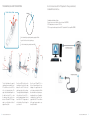
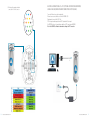
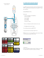
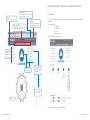
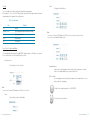
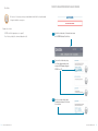
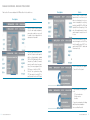
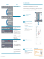
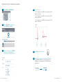
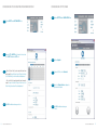
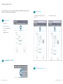
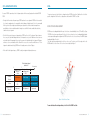
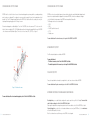
Quick Start Quick Start Guide Guide Rovins gyro to ins fore word rovins quick start guide Objective This guide describes how to install the ROVINS, and the basic configurations required before beginning the positioning Contents OBJECTIVE...........................................................................................................................................................................................01 CONTENTS...........................................................................................................................................................................................01 CONVENTIONS.....................................................................................................................................................................................02 ROVINS SYSTEM OVERVIEW.................................................................................................................................................................03 VERIFICATION OF PACK CONTENTS...................................................................................................................................................03 BASIC INSTALLATION..........................................................................................................................................................................03 STEP 1 - INSTALLING ROVINS...............................................................................................................................................................05 STEP 2 - ACTIVATING THE PRODUCT LICENSE....................................................................................................................................10 STEP 3 - CONFIGURING ROVINS.......................................................................................................................................................19 STEP 4. NAVIGATING WITH ROVINS.....................................................................................................................................................24 MORE......................................................................................................................................................................25 CUSTOMER SUPPORT..........................................................................................................................................................................29 IXSEA CONTACT...................................................................................................................................................................................30 2010-05/MU/ROVINS-001-B 1 Conventions ROVINS SYSTEM OVERVIEW The following conventions are used in this guide The ROVINS system is an Inertial Navigation System (INS). It delivers heading and attitude information as well as position and speed, to other systems or to display. It can receive data from other sensors to improve its accuracy. The ROVINS system can also be used as a gyrocompass. The core of ROVINS is an inertial measurement unit (IMU). The IMU is the assembly of three fiber optic gyroscopes (FOG) manufactured by IXSEA and three high precision pendulum-type accelerometers. The symbol leads you through nested menu items and/or dialog box options to a final action. Example: Logging Configure Logging Parameters means “Select Configure Logging Parameters option from the Logging pull down menu”. bold Bold text is used for items you must select or click in the software. It is also used for the field names used into the dialog box. Courier Text in this font denotes text or characters that you should enter from the keyboard, the proper names of disk Drives, paths, directories, programs, functions, filenames and extensions. You will find in the shipping case a Packing List detailing all the items delivered. This packing has been completed and checked by IXSEA shortly before shipment, and should match the contents of the pack you have received. italic Italic text is the result of an action in the procedures. However, we recommend that you check the contents of the pack and the equipment immediately on receipt of your ROVINS unit. Specifically, you should check that all the items referred to above are present on delivery and that none has sustained damage. Apart from its IMU, ROVINS contains a self-consistent navigation algorithm based on Kalman Filtering. This structure enables ROVINS to work either as a black box or to be connected to external sensor systems (GPS, Doppler Velocity Log, Depth sensor, acoustic positioning systems …). In conjunction with external sensors, ROVINS Kalman filter exceeds by several orders of magnitude the performances obtained with traditional navigation approaches ROVINS is delivered with a powerful and easy-to-use WEB-Based User Interface, which allows a complete configuration. VERIFICATION OF PACK CONTENTS If you observe any non-conformity or damage, please inform the carrier and IXSEA without delay by certified mail, describing in detail the problem encountered. BASIC INSTALLATION This guide describes how to install ROVINS with a GPS, and the basic configurations required before beginning the positioning. This is the basic installation. If you need to install additional external sensors, to define lever arms and/or to enter installation biases, please refer to ROVINS User Guide. ROVINS being versatile, you have to define its configuration to insure optimal operation. In this installation, we assume that ROVINS is aligned with respect to the vessel reference frame. This configuration includes: • Defining how ROVINS is installed on board (ROVINS orientation with respect to the vessel reference frame, ROVINS and GPS lever arms) • The cable connections to other equipment (connection to the workstation, connection to the GPS) • The activation of the product license • The communication link, the serial or Ethernet link, the activation of the GPS , the pulse input for Time synchronization System i.e., all settings to enter into ROVINS using the WEB-based User Interface • Navigation 2 2010-05/MU/ROVINS-001-B 2010-05/MU/ROVINS-001-B 3 Step 1: Installing ROVINS + GPS Step 3: Configuring To define the ROVINS orientation, lever arms, and the PC-ROVINS communication parameters To configure the GPS: serial or Ethernet input parameters, lever arm To define the Time Synchronisation system To define the initial position To activate the license code Step 2: Activating the product license To activate the GPS (i.e., to take the GPS data into account by the Kalman filter) Step 4: Navigating with ROVINS 5 min 4 2010-05/MU/ROVINS-001-B Heading standard deviation < 0.1 2010-05/MU/ROVINS-001-B 5 STEP 1- INSTALLING ROVINS ROVINS is fixed onboard using six CHC M6 screws. It can be installed with any orientation with respect to the vessel (see the definition of the vessel reference frame hereafter). The alignment of the unit is performed by means of the two centering pins located on the bottom plate of the ROVINS. You will find on Figure 1 all the mechanical information necessary to fix ROVINS. All inertial measurements are default performed with respect to ROVINS reference frame (X1, X2, X3). This reference frame is defined in Figure 1. Motion sensing measurements are default measured at ROVINS Center of Measurement P (see Figure 1). Figure 1 – Definition of ROVINS Reference Frame (X1,X2, X3) and P center of measurements Recommendations and Note Temperature in operation must be in the range -20 °C to 55 °C The dimensions of the ROVINS housing are ((l x ) in mm ): 374 x 213. There must be enough place for the wire way on the connector side of ROVINS • The weight of ROVINS is 14.6 in air and 4.65 in sea water • • 6 2010-05/MU/ROVINS-001-B ø 2010-05/MU/ROVINS-001-B 7 Electrical Connections: GPS + PPS (optional for Time synchonization) Standard Ethernet Link Case True Heading, Roll and Pitch Definitions Vessel reference frame North pole X N X X up W Standard case defined as follows: External sensor connected to the ethernet stream A of ROVINS: GPS Output protocol on stream A: GPS like PPS time synchronization pulse from the GPS cabled on the Pulse input B of ROVINS X in the horizontal plane pointing towards geographical North N X , parallel to the local vertical, pointing up X The roll is defined as the angle of rotation perform around the vessel XV1 so that the vessel axis XV2 lies in the local horizontal plane. This angle is default defined positive in the direction of axis XV1, i.e., when the boat port side is up. It varies between -180 and + 180°. The figure above is an illustration of the roll angle with null pitch. 8 2010-05/MU/ROVINS-001-B up W in the horizontal plane, pointing towards West Once the axis XV2 lies in the local horizontal plane, the pitch is the angle between the axis XV1 of the vessel and its projection in the local plane. This angle is default defined positive in the direction of the axis XV2, i.e., when the boat bow is down.. It varies from -90 to +90°. The figure above is an illustration of the pitch angle in case of null roll. Once the axes XV2 and XV1 lie in the local horizontal plane, the true heading is the angle between the vertical plane oriented in the North direction and the vertical plane passing through the vessel. Heading is counted positive from North, varying from 0 to 360°. The orientation of this angle is given above in case of null pitch and roll. 2010-05/MU/ROVINS-001-B 9 Electrical Connections: GPS + PPS (optional for Time synchonization) Serial Link Case (when Ethernet connection is not possible) GPS Antenna, Power supply, workstation connected to the Ethernet connector 1. 4. .3 .7 .12 8. 13. 17. 10 2010-05/MU/ROVINS-001-B .16 Case when Ethernet connection is not possible: External sensor connected to the serial link A of ROVINS: GPS Output protocol on serial link A: GPS like PPS time synchronization pulse from the GPS cabled on the Pulse input A of ROVINS In this case the workstation establishes a PPP connection with ROVINS Refer to the ROVINS User Manual to know how to configure this PPP connection .19 2010-05/MU/ROVINS-001-B 11 STEP 2. ACTIVATING THE PRODUCT LICENSE (ONLY FOR UPGRADE CASE) GPS Antenna, Power supply, workstation connected to the Central connector 1. 2. As soon as ROVINS is powered up it starts its alignment phase starting with the manually input position stored into ROVINS PROM. It is required that a valid initial position is input manually (see Step 3) or is given by the GPS. The alignment sequence is detailed in Step 4. 5. 6. 10. 11. 16. 17. 21. 22. 25. Launching the WEB-based User Interface 26. Required environment : • The workstation must be equipped with one of the following Web browser: Mozilla Firefox version 3.5 and higher Chrome version 4 and higher Safari version 4 and higher Opera version 10 and higher Internet Explorer version 7 and higher • Flash Player version 10 (and higher) must be installed on the workstation to visualize the compass • For the data logging: Java Runtime Environment 1.6 (and higher) They can be installed on your workstation from the provided IXSEA CD-ROM. The communication with the workstation is performed directly through the Ethernet link. ROVINS Web-based User Interface is then launched from the WEB browser hosted on the workstation. Its URL address is 192.168.36.1xx, xx being the two last numbers of the ROVINS serial number: 12 RS232 Cenral connector Power Function Link A Function Cenral connector Tx Pin 11 In Pin 1 Rx Pin 13 In GND Pin 2 Tx Rx GND_A Pin 8 RS422 Repeater/com with worksation RS232 Cenral connector Function Repeater Tx Pin 9 Rx Pin 15 Tx Rx GND_R Pin 5 Cenral connector Cenral connector Repeater/com with worksation RS422 Function Link A Function Repeater Tx + Pin 11 Tx + Pin 9 Tx - Pin 12 Tx - Pin 10 Pulse In Cenral connector Rx + Pin 14 Rx + Pin 16 Function Pulse A Rx - Pin 13 Rx - Pin 15 IN TTL Pin 20 Tx Rx GND_A Pin 8 Tx Rx GND_R Pin 5 GND_A Pin 21 2010-05/MU/ROVINS-001-B The Control Pages opens: During the first seconds the IXSEA logo is flashing gray/blue indicating that the Web-based User Interface is loading the internal configuration of ROVINS. Then the logo turns blue, the alignment sequence of ROVINS begins. 2010-05/MU/ROVINS-001-B 13 WEB-Based User Interface - General Rules, Commands and Navigation Menu Bar The menu is blue when selected Maintenance page : Firmware upgrades, system restaring, factory settings reset, support contact. Navigation data window: It displays all data either computer by ROVINS or coming from external sensors IXSEA logo handling options page : position selection, language selection , day/night mode selection A click on the IXSEA logo opens the detailed status/activation pop-up window and the compass disappears. This window: • Sums-up the status of The input ports The output ports The system The external sensors • Enables the external sensors activation Heading, Roll, Pitch,Heave and Speed data System Status: color and verbose display Latitude,Longitude and Depth or UTM positions and Depth data UTM northing UTM easting Depth 4784416.50 m 714025.03 m 25.30 m Compass area You can close the pop-up by clicking on the IXSEA logo. 14 2010-05/MU/ROVINS-001-B 2010-05/MU/ROVINS-001-B 15 Color Code The color code applies for the indicators and text labels displayed in this pop-up window. When a problem occurs, the color of the IXSEA logo changes and the detailed status pop-up automatically appears showing immediately which equipment has raised the problem. Text box • By typing it in the dedicated area: Table 1 – Color code definition Color Definition Grey inactivity Flashing Grey/Blue System Configuration (during initialization for example) Blue Activity, nominal operation Orange Activity, warning Red Activity, alarm Note You can also use the up arrow ([]) and down arrow ([]) keys to increase or decrease the numerical values. Incorrect value are immediately indicated by red color: General Rules for Using Command Windows The command windows allow you to display or modify ROVINS configuration parameters. At first delivery, these parameters are set to default values. You have to modify them to fit your needs: Scrolling list selection • By selecting it directly in the scrolling list: Expanding hidden area In order to keep each web-based page as small as possible, only the main parameters are default visible. You can expand the hidden area by clicking on its text label title: OK/Cancel buttons Each command page contains the same buttons, they appear as soon as a modification or a selection has been made in the command page: Note you can also use the up arrow ([]) and down arrow ([]) keys to scroll in the list. To validate the new configuration and store it in the ROVINS PROM. To return to the previous entered values. Tick box 16 • By selecting it by clicking in the dedicated box: 2010-05/MU/ROVINS-001-B 2010-05/MU/ROVINS-001-B 17 Product License Activation (only in case of upgrade) Other Button On “mouse over” action, orange color may surround a button to indicate that the action performed by clicking on the button has consequences. Examples of such action: • ROVINS restart (the alignment process is repeated) • Reset to factory settings (the customized configuration is lost) Step 1: Ask for the activation code: click on maintenance menu on the ROVINS Web-based User Interface. Step 2: To recover the activation code, using the «Contact Support» button, send a message to IXSEA support giving your ROVINS license ID. Step 3: Enter the recovered activation code in the dedicated text box and click «Activate License» button. 18 2010-05/MU/ROVINS-001-B 2010-05/MU/ROVINS-001-B 19 WEB-based User Interface - Menus and Options Overview Menu /options Find hereafter all the menus and options of the WEB-based User Interface and their uses Menu /options Used to … Define the ROVINS orientation, possible roll, pitch and heading misalignments, primary and secondary lever arms useful to compute the heave and position for the output protocols that provide it Define the couple (external sensor or UTC, input link): the protocol used to input the data, the serial (parity, baud rate, standard (RS232 or RS422) and stop bit) or Ethernet (transport layer, IP address, Port number) parameters, and the external sensor parameters (lever arms, misalignments (for the DVL), beacon selection (for the USBL) Define the Time synchronization settings (UTC): pulse input selection for the PPS signal, the protocol to use for the PPS signal Used to … Define the outputs: the protocol used to output the data, the lever Arm to use, the data rate or the input pulse to use to synchronize the output data, the serial (parity, baud rate, standard (RS232 or RS422) and stop bit)or Ethernet (transport layer, IP address, Port number) parameters, the pulse output to output the envelop, the heave filter to use Define the Network parameters for communication through a serial link (PPP option) or through Ethernet one (DHCP client mode activation, ROVINS IP address and Network mask to use) • Enter the initial position, save it, update it • Choose the Zero Velocity mode To be informed in case of warning or error for UTC synchronization loss Position sensor loss Speed loss • To generate a warning when the heading and/or the position standard devia tion cross a defined threshold • 20 2010-05/MU/ROVINS-001-B 2010-05/MU/ROVINS-001-B 21 Menu /options Used to … To launch the DVL calibration STEP 3. CONFIGURING ROVINS Configuring the ROVINS Orientation with Respect to the Vehicle As ROVINS can be installed with any orientation with respect to the vehicle, ROVINS axes orientation can be different from vehicle axes orientation, with 90 degrees rotations of any of the ROVINS axis with respect to the vehicle axes. Step 1: Choose MECHANICAL PARAMETERS under INSTALLATION Menu To save /restore product settings Step 2: • The direction to which the IXSEA logo side is pointing. >In the illustration, ROVINS logo side points to the chosen direction. • The direction to which the ROVINS connectors side is pointing. >In the illustration, ROVINS connectors side points to the chosen direction. Log the data of the repeater output or of any A to E output. Restart your ROVINS Unit Update the system: firmware, loader, and/or WEBBasedUser Interface versions • To activate your license by entering the activation code • Get ROVINS serial number and WEBbased User Interface • Contact IXSEA Support • • Display all navigation data computed and received by ROVINS Step 3: Click the OK button to validate your choice. Choose the position coordinate representation (latitude/longitude or UTM coordinates) Choose the display mode (night/day mode) Choose the WEB-based language (English or French) 22 2010-05/MU/ROVINS-001-B Step 4: Click on Restart button in the warning window that appears in the upper part of the Mechanical Parameters page. >ROVINS restarts, and alignment sequence (see step. 4) is repeated. 2010-05/MU/ROVINS-001-B 23 Configuring the GPS Input Stream and GPS Parameters Step 1: Choose INPUTS under INSTALLATION Menu Step 4: Define the GPS lever arms: • LV1 is the signed distance from the ROVINS center of measurements to the GPS along axis 1 of the illustration • LV2 is the signed distance from the ROVINS center of measurements to the GPS along axis 2 of the illustration • LV3 is the signed distance from the ROVINS center of measurements to the GPS along axis 3 of the illustration 24 Step 2: Associate GPS to INPUT A by clicking in the intersection of the INPUT A column and GPS row Step 3: Configure the relevant parameters of the INPUT A by choosing them in the various drop-down lists of the Protocol, Physical Link, Serial and/or Ethernet areas. 2010-05/MU/ROVINS-001-B Step 5: Click OK to validate and save your choices. Step 6: Activate the GPS (i.e., take into account the GPS data into the ROVINS Kalman filter): In EXTERNAL SENSORS area (that is the detailed status pop-up in the CONTROl page), set the activation parameter of the GPS to ON position by clicking on OFF button. 2010-05/MU/ROVINS-001-B 25 Configuring the pps for using time synchronization system Configuring the output stream Step 1: Choose OUTPUTS under INSTALLATION Menu Step 1: Choose INPUTS under INSTALLATION Menu Step 2: Associate UTC to INPUT A by clicking in the intersection of the INPUT A column and UTC row Step 2: Click on Output A. Step 3: • For an Ethernet link, the pulse input will come from pulse input B: choose Ethernet for the Physical Link then select Pulse B for Synchro In and the desired protocol • For a serial link, the pulse input will come from pulse input A: choose Serial for the Physical Link then select Pulse A for Synchro In and the desired protocol. Step 4: Click OK to validate and save your choices. Step 3: Choose «GPS like» in the Protocol list Step 4: Select the Physical Link and configure its parameters if needed. Step 5: Click OK to validate and save your choices. 26 2010-05/MU/ROVINS-001-B 2010-05/MU/ROVINS-001-B 27 entering the initial position Entering the initial position is only necessary if no GPS is available upon starting ROVINS. Once saved by clicking on OK button, the entered position is used at next ROVINS start. Step 3: Enter the initial position: • Either Latitude (in degrees), Longitude (in degrees) and depth (in meters) • or the UTM coodinates of this position Step 1: To define the position : • Click options menu In the Coordinate System area : • Either select Latitude/longitude option • Or UTM option • Click OK button to validate Step 2: Choose INIT&UPDATE under SETUP Menu Step 4: Click OK to validate and save your choices. 28 2010-05/MU/ROVINS-001-B 2010-05/MU/ROVINS-001-B 29 STEP 4. NAVIGATING WITH ROVINS MORE… As soon as ROVINS is powered on, it starts its alignment phase with the manually input position stored into ROVINS PROM. The previous steps consist only of the basic configuration of your ROVINS system. You will find hereafter a list of other possible configurations. Details on these configurations can be found in the ROVINS User Guide. • During the first five minutes after powering-on, ROVINS performs its coarse alignment: ROVINS inertial sensor data (accelerometers and gyrometers) are computed to estimate heading, roll and pitch angles. At sea it is recommended that the system is kept as steady as possible during coarse alignment: oscillations around a mean position are permitted but accelerations should be avoided. Leaving the vessel adrift for 5 minutes would lead to satisfactory conditions for coarse alignment. After the first fine minutes long coarse alignment phase, ROVINS switches to the “fine alignment” phase to improve the accuracy of roll, pitch and heading estimations. Such improved accuracy is useful if data from external sensors are not available right at the beginning of the mission. Any movement is allowed during the fine alignment. 90 degrees rotations are even recommended so that the Kalman filter assesses the sensors bias on different axes. The fine alignment is ended automatically by ROVINS when the heading covariance is below 0.1degree. • At the end of the fine alignment process, ROVINS is ready for navigation with optimal performances. • 0 5 When heading standard deviation <0.1 ROVINS measures heading and attitude with respect to its reference frame defined by the 3 axes X1, X2 and X3 (see Figure 1). ROVINS reference frame may not be parallel to the vehicle reference frame. In such case, heading and attitude outputs can be compensated for angular misalignments of ROVINS relative to the vehicle reference frame so that ROVINS outputs heading and attitude of the vehicle. This is done by setting misalignment bias for the three reference axis. These biases are the Euler angles which relate ROVINS and vehicle reference frame. Vehicle reference frame is depicted on Figure 2. Time in minutes Navigation = Static or max speed < 3 knot Navigation with large heading variations (>90°) Invalid output Reliable output Full accuracy output Position = Position given by the GPS Reliable output Full accuracy output Flag in the System status area Alignement Fine Alignement System ready Heading & Attitude ROVINS to Vehicle misalignment Figure 2 - Vehicle Reference Frame For more details about the misalignment bias, refer to Part 2 of the ROVINS User Guide. 30 2010-05/MU/ROVINS-001-B 2010-05/MU/ROVINS-001-B 31 Configuring the output stream Configuring the output stream ROVINS is able to calculate the heave of several external monitoring point: one primary and three secondary monitoring points can be user-configured. The secondary lever arms are used to compute the heave for the output protocols that provide it (see Part IV- Configuration and Operation of the ROVINS User Guide to define the secondary lever arms), the output position being always given for the Primary lever arm.. ROVINS uses external sensor data to improve its own estimates of position, speed, attitude and, heading. In order to prevent corrupted external data to degrade the estimation of ROVINS, external sensor data passe through a rejection filter before being incorporate into ROVINS main computation Kalman filter. The following external sensors can be added: • A DVL • A LBL • An USBL (up to three beacons) • A CTD • A depth sensor External monitoring points are defined by their “Lever Arm” to ROVINS center of measurement P. This lever arm is the triplet of cartesian coordinates (LV1, LV2, LV3) defining the position of external monitoring point M with respect to ROVINS center of measurement P (defined in Figure 1) in the vessel reference frame (XV1, XV2, XV3) - see Figure 3. For more details about the external sensors, refer to part 4 of the ROVINS User GUIDE Ethernet Input/output Five Ethernet inputs/outputs are available on ROVINS. For more details about • The Ethernet connector, refer to Part 2 of the ROVINS User Guide • The available protocols for this connectors, refer to part 5 of the ROVINS User Guide. Pulse Input/Output Four pulse inputs and two external pulse coming from the central connector are available on ROVINS. For more details about the pulse connector pins, refer to Part 2 of the ROVINS User Guide. Figure 3 - Definition of lever arms Extended Functions of the WEB-based User Interface For more details about the external monitoring points, refer to Part 2 of the ROVINS User Guide. 32 2010-05/MU/ROVINS-001-B Recording data: you can record the data coming from the repeater port or of any of the A to E output. For more details about the data recording refer to Part 4 of the ROVINS User Guide. Observing the input data flow coming from any input stream. For more details refer to Part 4 of ROVINS User Guide. System Information: to accede to the serial number and firmware version of your ROVINS unit, click on maintenance menu of the WEB-based User Interface. Note: these information are useful when you contact IXSEA technical support. 2010-05/MU/ROVINS-001-B 33 ROVINS Zero Velocity Update (ZUPT) Modes customer support These modes have been designed to use ROVINS for specific applications when no external sensor is connected. For more details about ZUPT mode, refer to part 4 of the ROVINS User Guide. THE WORLDWIDE 24/7 TELEPHONE SUPPORT LINE NUMBERS ARE: [ EMEA +33 (0)1 30 08 98 98 USA +1 888 660 8836 (toll free) ASIA +65 6747 7027 To contact customer support for any IXSEA products, a general mail box is available with the following address: [email protected] 34 2010-05/MU/ROVINS-001-B 2010-05/MU/ROVINS-001-B 35 ixsea contact PERSONAL NOTES To obtain information on any IXSEA products, a general mail box is available with the following address: [email protected] You can also contact IXSEA headquarters in France, or one of its representatives around the Contact 36 Phone Fax IXSEA SAS France +33 (0)1 30 08 98 88 +33 (0)1 30 08 88 01 IXSEA BV The Netherlands +31 (0)23 750 5110 +31 (0)23 750 5111 IXSEA GmbH Germany +49 (0)511 123 59575 +49 (0)511 123 59576 IXSEA Ltd - Main office IXSEA Ltd - Aberdeen office United Kingdom + 44 1730 260222 + 44 1224 355160 +44 1730 260333 IXSEA LLC United Arab Emirates +971 4 3117135 +971 4 3328860 IXSEA Inc Usa +1 (888) 660 8836 +1 (781) 937 8806 IXSEA Pte Ltd Singapore +65 6747 4912 +65 6747 4913 IXSEA Pte Ltd China +86 (0)10 6211 4716 +86 (0)10 6211 4718 IXSEA Pty Ltd Australia +61 (0)7 3390 4660 +61 (0)7 3390 7242 2010-05/MU/ROVINS-001-B 2010-05/MU/ROVINS-001-B 37 PERSONAL NOTES 38 2010-05/MU/ROVINS-001-B PERSONAL NOTES 2010-05/MU/ROVINS-001-B 39