1
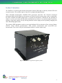
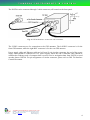
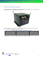
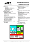
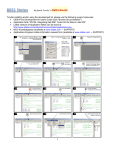
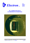
 TungRay Instruments & Control
TIC INS700
User’s
Manual
Tungray Instruments & Control Pte. Ltd
Block 51 Ayer Rajah Crescent #02-09 Singapore 139948
Tel: (65) 6776 1070 Fax: (65) 6776 2610
15
TT UU N
O LL N TT RR O
ON
& CC O
N TT SS &
M EE N
N SS TT RR UU M
N GG RR AA YY II N
Table of Contents Section 1. Introduce ............................................................................................................................................. 1 Section 2. Scope of delivery.................................................................................................................................. 2 Section 3. Hardware overview and connection ................................................................................................... 3 Section 4. Installation ........................................................................................................................................... 5 Section 5. Led definitions ..................................................................................................................................... 6 Section 6. Software overview ............................................................................................................................... 7 Section 7. System specification ............................................................................................................................ 8 Section 8. Maintenance ........................................................................................................................................ 9 Accelerometer testing procedure .................................................................................................................... 9 Gyro testing procedure .................................................................................................................................... 9 GPS testing procedure .................................................................................................................................... 10 Calibration ...................................................................................................................................................... 10 Section 10. Coordinate conventions .................................................................................................................. 11 Section 11. Common acronyms .......................................................................................................................... 12 Section 12. Revision history ................................................................................................................................ 13 TungRay Instruments & Control Pte Ltd
Co. Reg. No.:
200719313W
Address: Block 51 Ayer Rajah Crescent #02-09 Singapore 139948
Tel: (65) 6776 1070 / 6773 0170
Fax: (65) 6776 2610
website:
www.tic.sg
email: [email protected] 15
TT UU N
O LL N TT RR O
ON
& CC O
N TT SS &
M EE N
N SS TT RR UU M
N GG RR AA YY II N
Section 1. Introduce
TIC INS700 is a tactical grade Inertial Navigation System (INS) that is aided by internal GPS and
external encoder. The encoder input is from user’s program through Ethernet.
Three Fizoptika tactical-grade VG095M FOG gyroscopes and three TIC in-house developed
navigation-grade QA100 quartz accelerometers are used as inertial sensors. Due to the exceptionally
low bias variation and small output noise of QA100 accelerometers, INS700 has the potential to
achieve very low error in its roll and pitch measurements as well as a very smooth output in position,
making it especially suitable for any moving platform used for high precision pointing, mapping and
other demanding applications.
The 18-states EKF algorithm is used to correct and calibrate INS error based on Zero-velocity Update
(ZUPT), wheel encoder measurements, GPS position measurement and vector-GPS yaw
measurement. The vector-GPS yaw measurement feature is a future option only.
Fig. 1: The INS700 integrated navigation system.
TungRay Instruments & Control Pte Ltd
Co. Reg. No.:
200719313W
Address: Block 51 Ayer Rajah Crescent #02-09 Singapore 139948
Tel: (65) 6776 1070 / 6773 0170
Fax: (65) 6776 2610
website:
www.tic.sg
email: [email protected] 1 15
TT UU N
O LL N TT RR O
ON
& CC O
N TT SS &
M EE N
N SS TT RR UU M
N GG RR AA YY II N
Section 2. Scope of delivery The INS700 are supplied with cables, GPS antenna, embedded software and manual. Table 1 lists all
the items that are delivered with the INS700.
Table 1. Summary of INS700 system components.
Qty
1
1
2
2
1
Description
System unit
Power supply cable and Ethernet cable. 2 cables are led from one connector.
GPS antenna cable (for front GPS only)
GPS antenna (for front GPS only)
Embedded navigation EKF software. The software has been installed inside system unit
1
1
Hard copy of ICD document
Hard copy of user manual (This document)
In addition to the components supplied, the users need to prepare their own laptop or PC to configure
INS700 and read navigation data from system unit.
TungRay Instruments & Control Pte Ltd
Co. Reg. No.:
200719313W
Address: Block 51 Ayer Rajah Crescent #02-09 Singapore 139948
Tel: (65) 6776 1070 / 6773 0170
Fax: (65) 6776 2610
website:
www.tic.sg
email: [email protected] 2 15
TT UU N
O LL N TT RR O
ON
& CC O
N TT SS &
M EE N
N SS TT RR UU M
N GG RR AA YY II N
Section 3. Hardware overview and connection An overview of the INS700 hardware structure is given in Fig. 2 below.
Fig. 2: Overview of INS700 internal hardware structure and labeled parts.
The Vector GPS receiver is only future extension. For standard INS700 version 2, GPS dada is from
the Ubloc GPS receiver chip installed on the Utility board. So the rear GPS antenna is also not in use.
From INS700 Version 2, a power supply protector module has been integrated into the design. This
protector can protect other components from possible damage caused by lower or higher voltage of
the 12V power supply. With this protector, an input voltage less than 11V will not be able to start up
INS and the power will be cut off automatically if input voltage is lower than 9V or higher than 16V
during INS working.
TungRay Instruments & Control Pte Ltd
Co. Reg. No.:
200719313W
Address: Block 51 Ayer Rajah Crescent #02-09 Singapore 139948
Tel: (65) 6776 1070 / 6773 0170
Fax: (65) 6776 2610
website:
www.tic.sg
email: [email protected] 3 15
TT UU N
O LL N TT RR O
ON
& CC O
N TT SS &
M EE N
N SS TT RR UU M
N GG RR AA YY II N
The INS700 can be connected through 3 cable connectors, all located on the front panel.
Fig. 3: INS700 hardware connection and orientation.
The 2 BNC connectors are for connection to the GPS antennas. The left BNC connector is for the
front GPS antenna, while the right BNC connector is for the rear GPS antenna.
Power supply cable and Ethernet cable are led from 12-pin circular connector, the end of the power
supply cable should be connected to 12V power supply, while the end of Ethernet cable should be
connected to Ethernet card of computer that is used to receive navigation data from INS700 or send
encoder data to INS700. For pin assignment of circular connector, please refer to INS 700 Interface
Control Document. TungRay Instruments & Control Pte Ltd
Co. Reg. No.:
200719313W
Address: Block 51 Ayer Rajah Crescent #02-09 Singapore 139948
Tel: (65) 6776 1070 / 6773 0170
Fax: (65) 6776 2610
website:
www.tic.sg
email: [email protected] 4 15
TT UU N
O LL N TT RR O
ON
& CC O
N TT SS &
M EE N
N SS TT RR UU M
N GG RR AA YY II N
Section 4. Installation There are 8 mounting holes in INS700 base plane. User is recommended to select 4 suitable holes
from the 8 to install INS700 on their system The figures below are the mechanical drawings for the
INS700 outline and mounting holes.
Fig. 4: top and side view of the Tic INS700, showing mounting holes
Fig. 5: outline of Tic INS700
In most circumstances the INS700 should be mounted directly onto the chassis of user system (say
robotic vehicle), and X direction of INS should point to front of user’s system, Y direction of INS
should point to right of user’s system (please refer to Fig.3).
2 GPS antennas should be mounted in a good, open location and on a suitable ground plane such as
the roof of a robotic vehicle. To ensure the accuracy of Vector-GPS yaw measurement, the 2 GPS
antennas should be mounted with a horizontal separation distance not less than 0.5m.
TungRay Instruments & Control Pte Ltd
Co. Reg. No.:
200719313W
Address: Block 51 Ayer Rajah Crescent #02-09 Singapore 139948
Tel: (65) 6776 1070 / 6773 0170
Fax: (65) 6776 2610
website:
www.tic.sg
email: [email protected] 5 15
TT UU N
O LL N TT RR O
ON
& CC O
N TT SS &
M EE N
N SS TT RR UU M
N GG RR AA YY II N
Section 5. Led definitions
The front panel has a status LED, the LED can indicate whether INS 700 is working normally. The
LED will flash green color initially once power up. After Gumstixs initialization finish (initialization
will take about 40 seconds), the LED will flash green color and red color alternately. No green color
flash means there are damages or errors in IMU sensor, no red color flash means there are damages
or error in Gumstixs or navigation EKF software.
TungRay Instruments & Control Pte Ltd
Co. Reg. No.:
200719313W
Address: Block 51 Ayer Rajah Crescent #02-09 Singapore 139948
Tel: (65) 6776 1070 / 6773 0170
Fax: (65) 6776 2610
website:
www.tic.sg
email: [email protected] 6 15
TT UU N
O LL N TT RR O
ON
& CC O
N TT SS &
M EE N
N SS TT RR UU M
N GG RR AA YY II N
Section 6. Software overview The TicNav navigation software comes preinstalled with Tic INS700. A data flow diagram is shown
in Fig. 2 below.
Fig. 6: Data flow diagram of the TicNav navigation software.
Detailed data structure of the above data packets is defined in INS700 Interface Control Document.
TungRay Instruments & Control Pte Ltd
Co. Reg. No.:
200719313W
Address: Block 51 Ayer Rajah Crescent #02-09 Singapore 139948
Tel: (65) 6776 1070 / 6773 0170
Fax: (65) 6776 2610
website:
www.tic.sg
email: [email protected] 7 15
TT UU N
O LL N TT RR O
ON
& CC O
N TT SS &
M EE N
N SS TT RR UU M
N GG RR AA YY II N
Section 7. System specification
Physical Parameters
•
Dimension: 125mm(D) x138.5mm(W) x 108mm(H)
•
Weight: 1.5kg (2kg for V1 (the earlier version))
•
Power: 12V+/- 5% DC input, 12W max, 8W typical
System Configuration
•
Gyroscope: 3x Fizoptika VG095M Fiber-Optics Rotation Sensors
•
Accelerometer: 3x TIC QA100 rebalanced quartz pendulum accelerometers
•
GPS Receiver: 1x Ublox LEA-5S module (default) and 1x Hemisphere vector GPS receiver
(for future extension only).
•
IUM DAQ Module: 1x TIC DAQ V2, with C8051F340 uC and ADS1256 24-bit delta-sigma
ADCs
•
INS Computer: 1x Gumstix Verdex Pro XL6P, with Xscale PXA270 processor, 600MHz
•
Power Supplier: 1x TIC Utility Board
•
Firmware: TicNav3A with standard strap-down INS algorithm and 18-state EKF algorithm
System Performance (typical value):
•
Position Accuracy:
o With Encoder: typically 3% of distance travelled
o With GPS: typically 3m horizontal and 5m vertical under good GPS reception
o 60sec after GPS outage: within 10m
•
Velocity Accuracy:
o Within 0.2m/s as long as encoder data is available
•
Attitude Accuracy:
o Roll: 0.15 deg(static) +0.35 deg (dynamic)
o Pitch: 0.15 deg (static) + 0.35 deg (dynamic)
o Yaw – In-door mode: 30 deg/hr(static) + 0.35 deg (dynamic)
o Yaw – Out-door mode with GPS: 1 deg(static) + 0.35 deg (dynamic)
TungRay Instruments & Control Pte Ltd
Co. Reg. No.:
200719313W
Address: Block 51 Ayer Rajah Crescent #02-09 Singapore 139948
Tel: (65) 6776 1070 / 6773 0170
Fax: (65) 6776 2610
website:
www.tic.sg
email: [email protected] 8 15
TT UU N
O LL N TT RR O
ON
& CC O
N TT SS &
M EE N
N SS TT RR UU M
N GG RR AA YY II N
Section 8. Maintenance
There are several checks that can be performed in the user’s site to ensure that the system is working
correctly. In this section, we provide some diagnostic procedures for user to verify the functionality
of accelerometers, gyroscopes as well as the build-in GPS receiver. If the problem remains, the user
should send the INS700 back to TIC for further diagnostic.
To ensure INS system has a sustained nice performance, it should also be sent back to TIC for
periodic calibration. The recommended calibration period is 6 months.
Accelerometer testing procedure Please follow this procedure to check if accelerometers are working correctly. 1. Connect Power to INS and connect Ethernet cable to host PC. Power on and wait about 1
minute so that embedded OS finish start-up.
2. Orient INS in the ways shown in table2.
3. Copy log file from INS folder /media/card into host PC and open file with text editor to check
accelerometers readings are within table2.
Table 2. Specification of INS orientation and accelerate measurement.
X
Orientation
Y
Accelerate measurement
Z
Horizontal
Horizontal
Down
Horizontal
Horizontal
Up
Down
Horizontal
Horizontal
Up
Horizontal
Horizontal
Horizontal
Down
Horizontal
Horizontal
Up
Horizontal
X-Accelerate between -1.5 and 1.5 m/s2
Y-Accelerate between -1.5 and 1.5 m/s2
Z-Accelerate between -7.8 and -11.8 m/s2
X-Accelerate between -1.5 and 1.5 m/s2
Y-Accelerate between -1.5 and 1.5 m/s2
Z-Accelerate between 7.8 and 11.8 m/s2
X-Accelerate between 7.8 and 11.8 m/s2
Y-Accelerate between -1.5 and 1.5 m/s2
Z-Accelerate between -1.5 and 1.5 m/s2
X-Accelerate between -7.8 and -11.8 m/s2
Y-Accelerate between -1.5 and 1.5 m/s2
Z-Accelerate between -1.5 and 1.5 m/s2
X-Accelerate between -1.5 and 1.5 m/s2
Y-Accelerate between -7.8 and -11.8 m/s2
Z-Accelerate between -1.5 and 1.5 m/s2
X-Accelerate between -1.5 and 1.5 m/s2
Y-Accelerate between 7.8 and 11.8 m/s2
Z-Accelerate between -1.5 and 1.5 m/s2
Typically a damaged accelerometer reading will exceed range list in above table.
Gyro testing procedure Please follow this procedure to check if gyros are working correctly.
TungRay Instruments & Control Pte Ltd
Co. Reg. No.:
200719313W
Address: Block 51 Ayer Rajah Crescent #02-09 Singapore 139948
Tel: (65) 6776 1070 / 6773 0170
Fax: (65) 6776 2610
website:
www.tic.sg
email: [email protected] 9 15
TT UU N
O LL N TT RR O
ON
& CC O
N TT SS &
M EE N
N SS TT RR UU M
N GG RR AA YY II N
1. Connect Power to INS and connect Ethernet cable to host PC. Power on and wait about 2
minutes so that embedded OS finish start-up.
2. Do not move INS and wait a few minutes.
3. Copy log file from INS /media/card into host PC and open file with text editor to check gyros
readings. Typically absolute value of a damaged gyro reading will exceed 0.2 rad/s (about
11.5 degree/s).
4. Power off and power on to restart INS, wait about 2 minutes so that embedded OS finish
start-up.
5. Rotate the INS based on right-hand rule according table3.
6. Copy log file from INS folder /media/card into host PC and open file with text editor to check
measurements according to table3.
Table 3. Specification of INS rotation and angular rate measurement.
X
C.C.W
C.W
0
0
0
0
Rotation
Y
0
0
C.C.W
C.W
0
0
Angular rate measurement
Z
0
0
0
0
C.C.W
C.W
X angular rate should be positive, others are small
X angular rate should be negative, others are small
Y angular rate should be positive, others are small
Y angular rate should be negative, others are small
Z angular rate should be positive, others are small
Z angular rate should be negative, others are small
GPS testing procedure Please follow this procedure to check if GPS is working correctly. To receive GPS signal clearly, the
user should do this test at outdoor ground.
1. Connect Power to INS and connect Ethernet cable to host PC. Power on and wait about 3
minutes so that embedded OS finish start-up and TicNav software finish initialization.
2. Continue to wait about 5 minutes so that more GPS data can be logged.
3. Copy log file from INS folder /media/card into host PC and open file with text editor to check
GPS data.
If GPS is working correctly, the readings of latitude and longitude should be close to actual values of
user’s site. Typically a damaged GPS could lead to empty log file or readings of GPS are zero.
Besides checking sensor working status through logging raw data, the user also can check IMU and
Gumstixs board working status through simply observing status LED installed in front panel. Please
refer to section 5 for specific LED definition.
Calibration With the using time of system increasing, the INS measurement error may increase gradually as well.
A calibration, when a specific time is elapsed, can rectify this error timely. The calibration elapse
suggested by TIC is half year (6 months), and INS700 should be sent back to TIC within every half
year for calibration.
TIC will offer once free calibration after delivery. Thereafter, the user must pay for calibration
service with a reasonable proposed quotation.
TungRay Instruments & Control Pte Ltd
Co. Reg. No.:
200719313W
Address: Block 51 Ayer Rajah Crescent #02-09 Singapore 139948
Tel: (65) 6776 1070 / 6773 0170
Fax: (65) 6776 2610
website:
www.tic.sg
email: [email protected] 10 15
TT UU N
O LL N TT RR O
ON
& CC O
N TT SS &
M EE N
N SS TT RR UU M
N GG RR AA YY II N
Section 10. Coordinate conventions
The INS700 uses a coordinate frame that is popular with most navigation systems. The below figure
shows how the three axes should be bound to INS box.
The below table lists the directions that the axes should point to when values of roll, pitch and raw
are zero and default mounting is used in user’s system.
Table 4. The directions that the axes should point to typically
Axes
Direction
User’s system
X
North
Forward
Y
East
Right
Z
Down
Down
If user use different mounting with default mounting list in table, the output of INS should be
translated by user self so as to be aligned with their own system coordinate.
TungRay Instruments & Control Pte Ltd
Co. Reg. No.:
200719313W
Address: Block 51 Ayer Rajah Crescent #02-09 Singapore 139948
Tel: (65) 6776 1070 / 6773 0170
Fax: (65) 6776 2610
website:
www.tic.sg
email: [email protected] 11 15
TT UU N
O LL N TT RR O
ON
& CC O
N TT SS &
M EE N
N SS TT RR UU M
N GG RR AA YY II N
Section 11. Common acronyms
Below is a list of common acronyms used in the User's Manual.
EKF: Extended Kalman Filter.
FOG: Fiber-Optic Gyroscope.
IMU: Inertial Measurement Unit.
INS: Inertial Navigation System.
ZUPT: Zero-velocity update.
TIC: Tungray Instruments & Controls Pte. Ltd.
TungRay Instruments & Control Pte Ltd
Co. Reg. No.:
200719313W
Address: Block 51 Ayer Rajah Crescent #02-09 Singapore 139948
Tel: (65) 6776 1070 / 6773 0170
Fax: (65) 6776 2610
website:
www.tic.sg
email: [email protected] 12 15
TT UU N
O LL N TT RR O
ON
& CC O
N TT SS &
M EE N
N SS TT RR UU M
N GG RR AA YY II N
Section 12. Revision history Revision
V01@March 01, 2010
V02@Nov 06, 2010
Comment
Initial Version
1. Split the document into usual
manual and ICD
2. Other updates
TungRay Instruments & Control Pte Ltd
Co. Reg. No.:
200719313W
Address: Block 51 Ayer Rajah Crescent #02-09 Singapore 139948
Tel: (65) 6776 1070 / 6773 0170
Fax: (65) 6776 2610
website:
www.tic.sg
email: [email protected] 13