1
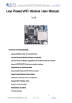
WIRELESS COMMUNICATIONS AND MOBILE COMPUTING
Wirel. Commun. Mob. Comput. 2005; 5:899–916
Published online in Wiley InterScience (www.interscience.wiley.com). DOI: 10.1002/wcm.354
NCTUns network simulation and emulation
for wireless resource management
Shie-Yuan Wang*,y and Yi-Bing Lin
Department of Computer Science and Information Engineering, National Chiao Tung University, Hsinchu, Taiwan
Summary
This paper describes NCTUns, an innovative network simulator and emulator for wireless and mobile networks.
Effects of various radio resource management and quality of service (QoS) schemes on higher-layer protocols and
real-world applications can be easily studied using NCTUns. In this paper, we elaborate on NCTUns simulation
methodology, architecture, design, functionalities, performance, and applications. NCTUns simulation for
wireless ad hoc, sensor, inter-vehicle communication networks, GPRS cellular networks, and wireless mesh
networks are also illustrated. More details about this tool can be found in http://NSL.csie.nctu.edu.tw/nctuns.html.
Copyright # 2005 John Wiley & Sons, Ltd.
KEY WORDS:
network simulation; network emulation; wireless network; radio resource management; QoS
1. Introduction
Radio resource management and quality of service
(QoS) schemes are important for next-generation
wireless and mobile networks. With them, scarce
wireless bandwidth can be more efficiently utilized
and applications demanding a certain level of QoS
(e.g., voice over IP) can be adequately supported.
Several radio resource management and QoS schemes
are being proposed for next-generation wireless and
mobile networks such as IEEE 802.16 WiMax networks and IEEE 802.11 WiFi networks with IEEE
802.11e QoS supports. Evaluating the performance of
these schemes in various conditions can help researchers discover their design flaws and performance
limitation.
In a network, providing QoS guarantees for an
application (e.g., VoIP) should be end-to-end and up
to the application layer. The effect of a radio resource
management or a QoS scheme on network-layer
routing protocols (e.g., IP), transport-layer protocols
(e.g., TCP/UDP), and application-layer protocols
(e.g., HTTP) should all be considered. Performance
analysis of these schemes at a lower layer such as the
MAC layer cannot reflect the real performance of
these applications. To obtain more realistic end-to-end
application-layer performance, the processing and the
interactions among these layers and real-world applications need to be investigated.
Network simulators are valuable tools for researchers to design, test, diagnose, and evaluate network protocols under various network conditions. Conducting
*Correspondence to: Shie-Yuan Wang, Department of Computer Science and Information Engineering, National Chiao Tung
University, Hsinchu, Taiwan.
y
E-mail: [email protected]
Contract/grant sponsor: MOE; contract/grant numbers: 91-E-FA06-4-4; NSC93-2752-E-0090005-PAE.
Copyright # 2005 John Wiley & Sons, Ltd.
900
S.-Y. WANG AND Y.-B. LIN
simulations is more economical, flexible, and safer
than performing real experiments. For example, in
large wireless and mobile networks where thousands
of nodes need to move, significant performance evaluation cost will be saved via simulations because one
need not to purchase many equipments to do the real
experiments. In addition, simulation results are easier
to analyze than experimental data because simulation
results are repeatable while experimental results
usually are unrepeatable due to many uncontrollable
factors in the real world. However, traditional network
simulators usually have the following drawbacks.
First, results of traditional simulations are not as
convincing as those produced by real hardware and
software equipment. In order to reduce development
complexity and cost, most network simulators only
simulate real-world network protocols and application
implementations with limited details. This abstraction
may lead to inaccurate results. For example, in ns-2
package [1], it is documented that ‘there is no dynamic receiver’s advertised window for TCP.’ As
another example, in a real network, a UDP-based
application program can change its destination host
(i.e., change the used destination IP address for an
outgoing UDP packet) at run time on a per-packet
basis. However, this cannot be done in ns-2 because
there is no concept of IP addresses in an ns-2 simulated network. In ns-2, a traffic generator agent needs
to be bound to a traffic sink agent at the beginning of a
simulation. During simulation, it cannot dynamically
change its destination node at run time like a normal
real-world application program does.
Second, existing and to-be-developed real-world
application programs may not be directly run with
traditional network simulators. Instead, applications
in these simulators need to be simplified and reimplemented as functions and compiled with the
simulation engine program. Such over-simplified
functions usually are not realistic (e.g., a generated
packet stream whose packet transmission time intervals are drawn from a statistic distribution). As such,
when the simulator runs as a user-level process on top
of the operating system’s kernel, a real-world application program cannot deliver packets to the simulator
via the standard UNIX POSIX system call API (e.g.,
socket(), sendto(), recvfrom(), etc.), because they run
at the same level. For this reason, the application
programs supported by a traditional network simulator are only those that have been simplified, modified,
and re-implemented in the simulator.
To overcome these problems, Wang invented a
kernel re-entering simulation methodology [2,3] and
Copyright # 2005 John Wiley & Sons, Ltd.
implemented it in the Harvard network simulator [4].
Later on, Wang improved the methodology in the
NCTUns 1.0 network simulator (referred to as
‘NCTUns’) [5]. Due to the kernel re-entering simulation methodology, NCTUns directly uses the realworld TCP/IP protocol stack in either FreeBSD or
Linux operating system to generate more accurate
simulation results than those generated by a simulator
that abstracts away a lot of protocol details. In addition, all existing or to-be-developed application programs that run on these operating systems can directly
run with NCTUns to generate realistic traffic for a
simulated network. These two properties enable researchers to evaluate the effect of a new radio resource
management or QoS scheme on real-world applications and their end-to-end performance [6].
Regarding network devices and protocols, supports
for wireless LAN networks, wireless mesh networks,
GPRS networks, QoS DiffServ networks, RTP/RTCP/
SIP VoIP protocols, and several other wireless standards such as IEEE 802.11(e) QoS protocol have been
added to NCTUns. Regarding simulation speed, we
have designed and implemented a new simulation engine that combines the advantages of the discrete-event
simulation methodology and the kernel re-entering
simulation methodology for fast simulation execution
[7]. Regarding operating system platform, NCTUns
can be run on both FreeBSD and Linux. Regarding
functionalities, NCTUns supports emulation, which
can evaluate a real-world network device without the
need to get, know, or modify its protocol stack. The
NCTUns network simulator can be easily turned into
an emulator by just selecting an option. During
emulation, a real-world network device can exchange
packets with a simulated device in NCTUns. One can
use this capability to test the protocol conformance
and interoperability of a network device [8].
This paper is organized as follows. Section 2
surveys related work. Section 3 briefly presents the
kernel re-entering sim ulation methodology. Section
4 presents the NCTUns high-level architecture. In
Section 5, we present the wireless radio resource
management support provided by NCTUns. In Section 6, we describe the emulation support provided
by NCTUns and how emulation can be applied to
wireless LAN mobile devices in the real world.
Section 7 illustrates how NCTUns is used to study
mobile ad hoc, sensor, inter-vehicle communication
(IVC) networks, wireless mesh networks, and general packet radio service (GPRS) networks. Section 8
discusses a performance optimization technique
that NCTUns employs to significantly speed up
Wirel. Commun. Mob. Comput. 2005; 5:899–916
NCTUns NETWORK SIMULATION AND EMULATION
901
wireless simulations. Finally, Section 9 concludes
this paper.
concurrently executed with the simulator during
simulation.
2. Related Work
3.
In the following, we discuss related work and the
differences between NCTUns and them.
Dummynet [9], when it was originally proposed,
also used tunnel interfaces to use the real-world TCP/
IP protocol stack in the simulation machine. However,
since its release in 1997, Dummynet has changed
substantially and now is used as a real-time traffic
shaper or a bandwidth and delay manager in the
FreeBSD kernel. It is no longer used as a network
simulator.
VMware [10] can implement virtual machines. It
can provide virtual x86-like hardware environments
within which a number of different operating systems
can be executed. With this capability, a number of
virtual machines can be implemented on a single real
machine to act as hosts or routers. They can be
configured to form an emulated network and packets
generated by real-world application programs run on
these virtual machines can be exchanged through the
emulated network. Although VMware can be used as
an emulator, it is not a network simulator. As such, its
result is not repeatable and a simulation case cannot
be finished more quickly than the simulated time in
the real world. In addition, it is very heavy weight. A
virtual machine consumes much resource and runs
substantially slower than the real machine—sometimes by an order of magnitude.
OPNET modeler [11], ns-2, and SSFnet [12] represent the traditional network simulation approach.
In this approach, the thread-supporting event scheduler, application code (not real-world application programs) that generates network traffic, utility programs
that configure, monitor, or gather statistics about a
simulated network, the TCP/IP protocol stack implementation on hosts, the IP protocol stack implementation on routers, and links are all compiled together to
form a single user-level program. A simulator constructed using this approach cannot easily provide
UNIX POSIX API for real-world application programs to run normally to generate network traffic.
Although some simulators may provide their own
non-standard API to let real-world application programs to interact with them (via IPC library calls),
real-world application programs still need to be
re-written so that they can use the internal API,
be compiled and linked with the simulator, and be
The kernel re-entering simulation methodology was
proposed in References [2,3,5], where tunnel network
interface is the key facility in the kernel re-entering
methodology. A tunnel network interface, available
on most UNIX machines, is a pseudo network interface that does not have a physical network attached to
it. The functions of a tunnel network interface, from
the kernel’s point of view, are the same as those of an
Ethernet network interface. A network application
program can send or receive packets through a tunnel
network interface, just as if these packets were sent to
or received from a normal Ethernet interface.
Each tunnel interface has a corresponding device
special file in the/dev directory. If an application
program opens a tunnel interface’s special file and
writes a packet into it, the packet will enter the kernel.
From the kernel’s viewpoint, the packet appears to
come from a real network and will pass through the
kernel’s TCP/IP protocol stack as an Ethernet packet
would do. On the other hand, if the application
program reads a packet from a tunnel interface’s
special file, the first packet in the tunnel interface’s
output queue will be dequeued and copied to the
application program. To the kernel, the packet appears
to have been transmitted onto a real link and this
pseudo transmission is not different from an Ethernet
packet transmission.
Using tunnel network interfaces, we can easily
simulate the wireless network depicted in Figure 1,
where a TCP sender application program running on
node 1 sends TCP packets to a TCP receiver application program running on node 2. We set up the virtual
simulated network with two operations. First, we
configure the kernel routing table of the simulation
machine so that tunnel network interface 1 is chosen
as the outgoing interface for the TCP packets sent
from node 1 to node 2 and tunnel network interface 2
is chosen for the TCP packets sent from node 2 to
node 1. Second, the wireless channel is simulated by a
simulation engine process. For the direction from
node i to node j (i ¼ 1 or 2 and j ¼ 3 i), the simulation engine opens the special files of tunnel network
interfaces i and j in /dev. It then executes a while loop.
In each step of this loop, it simulates a packet’s
transmission in the direction from node i to node j
by reading a packet from the special file of tunnel
Copyright # 2005 John Wiley & Sons, Ltd.
Simulation Methodology
Wirel. Commun. Mob. Comput. 2005; 5:899–916
902
S.-Y. WANG AND Y.-B. LIN
TCP_sender
TCP_receiver
Mobile Node 1
Mobile Node 2
Simulation Engine
TCP_sender
Route
Route
ARP
ARP
PSBM
PSBM
WMAC
WMAC
WPHY
WPHY
4.
TCP_receiver
User-level
Kernel
TCP/IP
Stack
Tunnel
interface 1
TCP/IP
Stack
Tunnel
interface 2
Fig. 1. The top single-hop TCP/IP wireless network can be
simulated by the bottom design.
interface i, waiting for the packet’s transmission on
the channel to finish (in virtual time), and then writing
this packet to the special file of tunnel interface j.
The bottom of Figure 1 depicts this simulation
scheme. Since replacing a real channel with a simulated channel happens outside the kernel, the kernels
on both nodes do not know that their packets actually
are exchanged in a simulated network. The TCP
sender and receiver programs, which run on top of
the kernels, do not know the fact, either. As a result,
all existing real-world application programs can run
on the simulated network, all existing real-world network utility programs can be executed in the simulation, and the TCP/IP network protocol stack used in
the simulation is the real-world implementation. Note
that in this simulation methodology, the kernel of the
simulation machine is shared by all simulated nodes.
Therefore, although two TCP/IP protocol stacks are
depicted in Figure 1, actually they are the same one—
the protocol stack of the simulation machine.
In addition to bandwidth and signal propagation
delay characteristics, we can simulate more interface
Copyright # 2005 John Wiley & Sons, Ltd.
details by adding more protocol modules to the
simulation engine. In this figure, we see that there is
one routing protocol module, ARP protocol module,
packet scheduling or buffer management module
(PSBM), IEEE 802.11(b) MAC module (WMAC),
and IEEE 802.11(b) wireless physical module
(WPHY) associated with each interface.
High-Level Architecture
NCTUns uses a distributed architecture to support
remote and concurrent simulations. This feature uses
an open-system architecture to enable protocol modules to be added to the simulator. This task can be
easily done in just a few mouse clicks via its GUI
operating environment. Functionally, NCTUns can be
divided into eight components described in the following subsections.
4.1.
GUI Operating Environment
The fully integrated GUI environment enables a user
to edit a network topology, configure the protocol
modules of a network node, set the parameter values
of a protocol module, specify mobile nodes’ moving
paths, plot performance curves, playback animations
of logged packet transfers, etc.
From a network topology, the GUI program can
generate a simulation job description file suite. Since
the GUI program uses Internet TCP/IP sockets to
communicate with other components, it can submit
a job to a remote simulation machine for execution.
When the simulation is finished, the simulation results
and generated log files are transferred back to the
GUI. The user then either examines logged data, plots
performance curves, or plays back packet transfer
animations.
During a simulation, the user can query or set an
object’s value (e.g., the routing table of a router or the
switch table of a switch) at any time. If the user does
not want to do any query or set operation during a
simulation, the user can choose to disconnect (but not
terminate) the currently running simulation so that he
(she) can use the GUI to handle other simulation jobs.
The user can later re-connect to a disconnected
simulation, regardless whether it is still running or
has finished. A user thus can submit many simulation
jobs simultaneously. This can increase simulation
throughput if multiple simulation machines are available to service these jobs concurrently.
Wirel. Commun. Mob. Comput. 2005; 5:899–916
NCTUns NETWORK SIMULATION AND EMULATION
4.2.
Simulation Engine
The NCTUns simulation engine is a user-level program that functions like a small operating system.
Through a defined API, it provides basic simulation
services to protocol modules (to be described later).
Such services include virtual clock maintenance,
timer management, event scheduling, variable registrations, etc. The simulation engine needs to be
compiled with various protocol modules to form a
single user-level program called ‘simulation server.’ A
simulation server takes a simulation job description
file suite as input, runs the simulation, and generates
data and packet transfer log files. When a simulation
server is running, it utilizes a lot of kernel resources.
Therefore, we do not allow other simulation servers to
run at the same time on the same machine.
4.3.
Protocol Module and Job Dispatcher
NCTUns supports various protocol modules. A protocol module implements a layer of a protocol stack
(e.g., the ARP protocol or a FIFO queue). A protocol
module is composed of a set of functions. It needs to
be compiled with the simulation engine to create a
simulation server. Inside the simulation server, multiple protocol modules can be chained to form a protocol stack.
The NCTUns simulation job dispatcher is a userlevel program that supports concurrent simulations on
multiple simulation machines. The job dispatcher
should be executed and remain alive to manage multiple simulation machines.
The job dispatcher coordinates a large number of
GUI users and a large number of simulation machines.
When a user submits a simulation job to the job
dispatcher, the dispatcher will select an available
simulation machine to execute this job. If no machine
is available, the submitted job can be queued and
managed by the dispatcher as a background job.
Various scheduling policies can be used to schedule
their service order [13].
4.4.
Coordinator
The NCTUns coordinator is a user-level program
executed on every machine where a simulation server
resides. The coordinator informs the job dispatcher
whether this machine is currently busy in running a
simulation or not. When executed, it first registers
itself with the dispatcher to join in the dispatcher’s
simulation machine farm. When its status (idle or
Copyright # 2005 John Wiley & Sons, Ltd.
903
busy) changes, the dispatcher is notified of this new
status. Based on the machine status information, the
dispatcher chooses an available machine from its
machine farm to service a job.
When the coordinator receives a job from the
dispatcher, it forks (executes) a simulation server
to simulate the specified network and protocols.
The forked simulation server process will kill itself
when its simulation is finished. During simulation, the
coordinator may also fork (start) or kill (end) some
real-world application programs as specified in the job.
Because the coordinator has the process IDs of the
forked traffic generators, it can register these traffic
generators with the kernel, and all time-related system
calls issued by these registered traffic generators will
be performed based on the virtual time of the simulated network, rather than the real time.
When the simulation server is running, the coordinator communicates with the job dispatcher and the
GUI program on behalf of the simulation server. For
example, the simulation server periodically sends the
current virtual time of the simulated network to the
coordinator. The coordinator then forwards this information to inform the GUI user of the simulation
progress. During simulation, the user can also on-line
set or retrieve an object’s value (e.g., to query or set a
switch’s switch table). Message exchanges between
the simulation server and the GUI program are performed via the coordinator.
4.5.
Kernel Modification
NCTUns modifies the kernel of the simulation machine so that a simulation server can correctly run on
it. During a simulation, the timers of TCP connections
in a simulated network should be triggered in the
simulation time rather than in the real time. The same
processing should also be applied to the time-related
services requested by the application programs that
are run on simulated nodes. For example, when the
kernel receives the sleep(5) system call issued by an
application program process, it should suspend the
execution of the process for 5 s in simulation time
rather than in real time.
Also, the kernel needs to automatically perform
UDP/TCP port mapping between a port number
specified by a simulation user and the port number
that is actually used inside the kernel. This mapping
allows multiple real-world application programs to
bind to the same port number on different nodes in a
simulated network. Consider an example where two
web server processes are running on two different
Wirel. Commun. Mob. Comput. 2005; 5:899–916
904
S.-Y. WANG AND Y.-B. LIN
nodes in a simulated network and they both want to
bind to the well-known port number 80. Without
converting these two 80 port numbers to two different
port numbers inside the kernel, the above setup cannot
be simulated due to port number collision.
4.6. User-Level Daemon and Real-World
Application Program
The NCTUns protocol daemons run at the user level to
perform specific jobs. For example, the real-world
‘routed’ (using the RIP routing protocol) or ‘gated’
(using the OSPF routing protocol) daemons run with
NCTUns to set up the routing tables in a simulated
network.
The NCTUns real-world application programs run
at the user level to either generate network traffic,
configure network, or monitor network traffic, etc. For
example, the tcpdump program can run on a simulated
network to capture packets flowing over a link and the
traceroute program can run on a simulated network to
find out the routing path traversed by a packet.
4.7. Remote, Concurrent, and
Parallel Simulations
NCTUns uses a distributed architecture, by which
simulation machines can be far away from the machines where the GUI programs are run. For example,
the simulation service machines may reside at NCTU
in Taiwan while the GUI users come from many
different places of the world. Multiple simulation
jobs can be concurrently simulated on different machines (one machine serves one job) to increase the
total simulation throughput.
When the NCTUns simulation jobs are run on
multiple machines, we say that NCTUns is operating
in the ‘multiple machine’ mode [13]. This mode
supports remote and concurrent simulations. In the
‘single-machine’ mode, the simulation jobs run on
the same machine. With the inter-process communication (IPC) design, NCTUns can be used for either
mode without changing its program code. Only the
mode parameter in its configuration file needs to be
changed.
NCTUns can also be turned into a parallel and
distributed network simulator. This is particularly
suitable for simulating a very large wireless network
with thousands of mobile nodes. In this mode, different nodes of a network are simulated by the NCTUns
simulation engines running on different machines.
The real-world application programs run on these
Copyright # 2005 John Wiley & Sons, Ltd.
mobile nodes are forked and executed on different
machines. This approach can effectively spread the
total memory space demand imposed by these application programs over multiple machines, hence overcoming the memory space limitation of a single
machine. We have used the conservative synchronization algorithm [14] to turn NCTUns into a parallel and
distributed network simulator that generates the same
simulation results as the sequential version.
5. Radio Resource Management
and QoS Supports
NCTUns supports radio resource management, QoS,
and mobility researches. It has been used in several
research work (e.g., [15–20]) to study these research
areas.
At the physical layer, the wireless channel models
supported include: (1) a simplified model like that
used in ns-2, where only a transmission range and an
interference range are specified for a wireless interface, (2) a two-ray ground reflection model that
considers large-scale path loss and computes the
received power at a distance. The computed power
is then compared against BER (bit error rate) versus
power versus modulation scheme versus encoding/
decoding scheme curves to derive a BER for the
received packet, (3) a Rayleigh fading model that
further considers the effect of small-scale fading and
multipath propagation. Depending on the focus of the
research, one can choose an appropriate physicallayer channel model to balance simulation result
accuracy and simulation speed.
At the MAC layer, the wireless MAC protocols
supported include: (1) CSMA/CA with RTS/CTS used
for IEEE 802.11(b) networks, (2) multiple frequency
time division multiplexed access (MF-TDMA) for
GPRS cellular networks, and (3) multichannel and
multiradio MAC protocols for reducing the bad effect
of signal interference in wireless mesh networks.
QoS support provided for IEEE 802.11(b) wireless
LAN networks is IEEE 802.11e protocol. NCTUns
includes a full implementation of enhanced distribution coordination function (EDCF) to differentiate
eight different priority traffic classes and hybrid coordination function (HCF) to support contention-free
medium accesses.
Replacing an existing protocol module with a new
one developed by a researcher can be easily done with
a few mouse clicks in the node editor of NCTUns.
Figure 2 shows that the node editor for a wireless LAN
Wirel. Commun. Mob. Comput. 2005; 5:899–916
NCTUns NETWORK SIMULATION AND EMULATION
905
Fig. 2. The node editor invoked for editing the protocol stack and protocol module parameters of a wireless LAN access point.
access point has been invoked. In this editor, the
modules used in the access point’s protocol stack
are shown and the parameters of the more advanced
wireless physical module are being set. More GUI
operation illustrations are available in Reference [21].
6. Emulation Supports
The NCTUns network simulator can be easily turned
into an emulator. With emulation, we can test the
functions and performance of a real-world host and
see how it would perform under various network
conditions without getting, knowing, or modifying
its internal protocol stack.
When NCTUns is operating as an emulator, a realworld host (e.g., a WLAN ad hoc mode mobile host, a
WLAN infrastructure mode mobile host, or a router)
can exchange packets with any node in a simulated
network. In the emulator mode, all nodes and links
specified in the simulated network are still simulated
by NCTUns (i.e., the simulation machine) where the
simulation speed is purposely slowed down to match
the speed of the wall clock.
Copyright # 2005 John Wiley & Sons, Ltd.
In NCTUns, a real-world device is referred to as
an ‘external node,’ and is represented by a different
node icon in the topology editor. The NCTUns
external nodes can interact with the simulated network in two configurations. In the first configuration
(see Figure 3(a)), the application programs running
on an external node can exchange packets with the
application programs running on a node in the
simulated network. For example, a TCP connection
can be set up between two application programs with
one running in the real network while the other
running in the simulated network. These two realworld application programs can then exchange their
packets via the TCP connection to complete a specific job (e.g., a web server and client completing a
web page retrieval). With this feature, network device developers can test whether their applications
and protocols conform to standards, specifications,
or inter-operability requirements before releasing
them to the market. For example, a newly developed
VoIP phone device can interact with a fully tested
VoIP program running in the simulated network to
see whether it can pass the interoperability and
conformance tests. This feature is enabled by the
Wirel. Commun. Mob. Comput. 2005; 5:899–916
906
S.-Y. WANG AND Y.-B. LIN
Fig. 3. The two different emulation configurations supported by NCTUns.
kernel re-entering simulation methodology and is
very unique.
Alternatively, two external hosts can exchange their
packets via the simulated network. In Figure 3(b), a
TCP connection is set up between two application
programs with one running on one external host, the
other running on another external host, and the TCP
connection traversing through several nodes in the
simulated network. Since the TCP packets exchanged
by these two real-world application programs need to
pass through the simulated network and experience
various simulated network characteristics, network
device developers can test how their applications
and protocols would perform under various network
conditions. For example, we can easily test the sound
quality generated by two VoIP phone devices when
the phone call needs to go through a simulated network with about 300 ms network delay and 10%
packet loss rate. Although existing emulators can
support this configuration, the simulated network
supported by them mostly is only a link abstraction,
which may delay, drop, and reorder real-world packets
based on a certain statistics distribution. In the
Copyright # 2005 John Wiley & Sons, Ltd.
NCTUns network emulator, on the other hand, the
simulated network where real-world packets go
through can be a complicated network with many
nodes. (The size of the simulated network can be very
large as long as the speed of the simulation machine’s
CPU can simulate the network at real time.) In
addition, in NCTUns, real-world packets can interact
and compete with the packet traffic dynamically
generated by application programs running on simulated nodes. This capability is illustrated in Figure
3(b) by showing that ‘TCP connection 1’ is competing
with ‘TCP connection 2’ for the bandwidth of the link
connecting R1 to R2. To our knowledge, no existing
emulators support this type of traffic mix between
simulated and real-world packets.
To describe the connectivity between an external
node and a simulated node, each external node is
represented by an external node icon in the simulated
network. A GUI user can easily specify the connectivity by drawing a link between an external node and
a simulated node. Lik e other links in the simulated
network, such a link has its own delay and bandwidth
properties simulated by NCTUns.
Wirel. Commun. Mob. Comput. 2005; 5:899–916
NCTUns NETWORK SIMULATION AND EMULATION
We note that the physical link connecting the
simulation machine and the external node need not
apply any MAC protocol processing to the real-world
packets when they are transmitted over the link.
Instead, it only needs to transfer the real-world packets from one end of the link to the other end of the link
as fast as possible. Simulations of properties (e.g.,
bandwidth, delay, BER, etc.) for the link connecting
the external node is done by the simulation engine.
Since the packets delivered from an external node
to a simulated node need to enter the simulation
machine, the external node must be physically connected to the simulation machine via some physical
network (can be as simple as a physical link). Ideally,
such a network should have infinite bandwidth and
zero latency. For example, a 100 Mbps Fast Ethernet
network may be used for this purpose. For NCTUns,
an external node must reside on the same subnet as the
simulation machine; otherwise, the emulation function will not work properly.
To receive the packets from an external node and
further inject them into the simulated network, a userlevel emulation daemon is run up on the simulation
machine for each external node. These daemons play
a similar role as a user-level network address translator (NAT) daemon. They intercept packets, translate
IP and port numbers, and then further inject packets
into their destinations (the simulated network or the
external hosts). Commands for running up these
daemons are automatically generated by the GUI
program and are automatically executed by the simulation engine. These user-level daemons may incur
extra latency during context switching. According to
our test results, a machine with 1 GHz CPU or above
can limit the packet latency caused by the emulation
daemon to within 100 Ms.
To direct an external node’s packets to the simulation machine, some routing entries must be set up
on the external node. To direct packets originated
from the simulated network to the external node, the
emulation daemon also needs some information. A
GUI user thus needs to do some settings on both the
external node and the simulation machine to ensure
that an emulation case works correctly.
6.1.
Adjusting Simulation Speed
Once a user adds an external node into the network
topology, the speed of the simulation engine will be
automatically set to the speed of the wall clock. This
means that during an emulation, the simulated network will be simulated at the speed of the wall clock.
Copyright # 2005 John Wiley & Sons, Ltd.
907
During an NCTUns emulation, the clock of the
simulated network is synchronized with the wall clock
every 1 ms, and therefore the emulation function’s
latency precision is about 1 ms. For example, suppose
that a user uses the real-world ping program to
measure the round-trip time of the path between an
external node and a simulated node and the round-trip
time (RTT) of this path is 100 ms in the simulated
network, then the reported RTT on the external node
may be some value between 99 and 101 ms.
From experimental results, we found that the precision may get worse if NCTUns is used in the singlemachine mode. During emulation, the GUI program,
simulation engine, traffic generator application programs, and some daemon programs compete for the
machine’s CPU cycles, which results in degraded
emulation precision. The time mismatch between the
simulation clock and the wall clock may increase up to
3 ms. However, we found that when NCTUns is used
in the multiple-machine mode, where the abovementioned components are run on separate machines,
the precision is quite high and seldom degrades.
6.2. Adding an External Node
to the Network Topology
An emulation is set up as follows. First, a user clicks
on the external node icon in the tool bar and add it to
the network topology. This is to indicate how the
external node is connected to the simulated network.
Second, the user enters the IP address used by that
external node in the real network through the GUI.
This information must be known by the emulation
daemon so that it can forward packets originated from
the simulated network to the external node.
Like any node in the simulated network, the GUI
will assign an IP address to each external node’s interface. This IP address is not a public IP address used in
the real world. Instead, it is a private IP address used in
the simulated network so that a user can specify the
destination IP address of a packet if he (she) intends to
send the packet to that node. To send packets to the
external node, a simulated node uses this assigned
private IP address as these packets’ destination IP
address. These packets will traverse the simulated
network as in the simulation mode and then reach the
external node represented in the simulated network.
The emulation daemon supporting this external node
will intercept these packets, change their destination IP
addresses from the one used in the simulated network
to the one used in the real network, and then forward
them to the external node in the real network.
Wirel. Commun. Mob. Comput. 2005; 5:899–916
908
S.-Y. WANG AND Y.-B. LIN
Now we describe how to direct traffic generated by
an external node to the simulated network (i.e., to the
simulation machine). Suppose that the simulation
machine’s IP address in the real world is 10.0.0.1
and the external machine’s IP address is 10.0.0.2, and
they are physically connected via an Ethernet cable.
Suppose that the external node makes a TCP connection to a simulated node whose assigned private IP
address is 1.0.3.1. Then on the external node, the user
should first execute the ‘route add 1.0/16 10.0.0.1’
command to add the required routing entry to the
system routing table.
In the above command, 1.0/16 means that the
destination network address is 1.0.X.X. (16 means
that the netmask is 255.255.0.0). Note that every node
in the simulated network is assigned a private IP
address of the form of 1.0.X.X. As such, the above
command indicates that all outgoing IP destination
address 1.0.X.X should be first sent to the gateway
whose IP address is 10.0.0.1. Since 10.0.0.1 is the
simulation machine’s IP address, these packets will be
delivered to the simulation machine.
When the packets generated by an external node
arrive at the simulation machine, we use the IP firewall facility provided by FreeBSD or Linux to intercept these packets and divert them to one emulation
daemon responsible for this external node. The required IP firewall rules are automatically generated by
the GUI program. They are automatically installed
into the operating system by NCTUns when an
emulation run is executed. Therefore, a user need
not install these firewall rules. When the emulation
daemon responsible for this, external node receives
these packets; it will function like an NAT to translate
their source IP addresses (which is the public IP
address of this external node) into the private IP
address assigned to this external node in the simulated
network. After this translation, the emulation daemon
will re-inject them into the kernel of the simulation
machine and these packets will traverse the simulated
network based on the routing tables stored in the
simulated network.
6.3.
Mobile Network Emulation
We give two examples of mobile network emulations:
mobile ad hoc network and mobile infrastructure
network.
(1) Mobile ad hoc network: NCTUns supports emulations with external mobile nodes, which can be
wireless LAN ad hoc mode or infrastructuremode devices. An external mobile node is repreCopyright # 2005 John Wiley & Sons, Ltd.
sented by a node in the simulated network and the
mobility of this node in the simulated network is
specified in the topology editor.
During emulation, the packets generated by the
external mobile node will be transferred to the
simulation machine and then enter the simulated
wireless network. For the simulated network,
these packets seem to be generated by the corresponding mobile node in the simulated network.
Since the corresponding mobile node uses a
wireless interface to connect to the simulated
wireless network (in either the ad hoc mode or
the infrastructure mode), these real-world packets
will be transferred wirelessly in the simulated network and may contend with other wireless packets that are generated in the simulated network.
Note that real-world packets will experience
the wireless MAC protocols (e.g., IEEE 802.11(b)
MAC) in the simulated network, rather than the
wireless MAC protocols that are implemented in
the wireless interface of the external mobile node.
This situation is similar to a fixed-network emulation where the link connecting the simulation
machine and an external node needs to deliver realworld packets between two ends of the link as fast as
possible and need not apply any MAC protocol
processing to them. In addition, because the moving
path of an external node is specified in the simulated
network rather than in the real world, an external
mobile node in the real world need not move.
Figure 4 shows an emulation example in which
one external ad-hoc mobile host (on the left)
communicates with a simulated mobile host (on
the right) via another simulated mobile host (in the
middle). Initially, the application running on the
external mobile host can exchange packets with
the application running on the mobile host on the
right via the middle mobile host. As time proceeds,
the external mobile host begins to move away from
the middle mobile host (not in the real world but
in the simulated network; the mobile host movement path can be easily set up as described in
Section 7) and it eventually moves out of the transmission range of the middle mobile host. During
this period, the application running on the external
node can no longer communicate with the application running on the mobile host on the right. Later
on, when the external node moves back to the mobile
node in the middle, the communication between
the two applications will be able to continue.
(2) Infrastructure-mode mobile network: The usage
of external infrastructure-mode mobile node is
Wirel. Commun. Mob. Comput. 2005; 5:899–916
NCTUns NETWORK SIMULATION AND EMULATION
909
Fig. 4. Mobile ad hoc network emulation.
similar to those of external hosts and external ad
hoc mode mobile nodes. The only difference is
that in the GUI dialog box of the external infrastructure-mode mobile node, the user needs to
provide the IP address of the gateway in the
simulated network for this mobile node.
Figure 5 shows an emulation example in which
one external infrastructure-mode mobile node in
the real-world communicates with a simulated host
at the top via a simulated wireless access point.
Like the ad hoc mobile node emulation case,
the external infrastructure-mode mobile node in
the real world may communicate with the simulated host at the top initially. As time proceeds, it
will leave the coverage (represented by the inner
circle) of the simulated wireless access point and
no longer can communicate with that simulated
host. Later on, when it enters the coverage area of
the simulated wireless access point again, the
communication continues.
7. Various Wireless Network Supports
This section describes the NCTUns supports on
various wireless networks.
Copyright # 2005 John Wiley & Sons, Ltd.
7.1.
Military, Sensor, IVC Mobile Ad Hoc Networks
In mobile ad hoc network studies, one usually wants
to change the protocol stack or the parameter values
used by mobile nodes to see how the changes would
affect the overall performance of the mobile network.
In NCTUns, this task can be easily done for thousands
of mobile nodes without requiring the user to configure individual mobile nodes. A user, before executing
a GUI command to automatically insert thousands of
mobile nodes into the topology editor, can first invoke
the node editor of the GUI to specify the protocol
stack and parameter values used for these mobile
nodes. With this setting, all inserted mobile nodes
will use the same protocol stack and parameter values.
In addition to protocol stack and parameter settings,
data and information fusion operation also useful in
mobile sensor networks to reduce traffic volume and
make intelligent decisions. In NCTUns, data and
information fusion agents running on each mobile
node can be conveniently implemented as user-level
application programs. This implementation provides
several advantages.
First, since such agents contain intelligence and are
usually complicated, it is better to implement them
separately rather than implement them as protocol
Wirel. Commun. Mob. Comput. 2005; 5:899–916
910
S.-Y. WANG AND Y.-B. LIN
Fig. 5. Wireless LAN infrastructure-mode network emulation.
modules and mix their codes with the simulation
engine code. Second, such agents may have been
implemented as application programs and are being
used in real-world sensor networks (e.g., there are
several commercial companies selling sensor network
products in the market). Since real-world application
programs can directly run on simulated nodes in
NCTUns, all developed data fusion agent programs
can readily run with NCTUns. Third, since application programs developed for simulations can directly
run on real machines in NCTUns, it is advantageous to
develop data and information fusion agents as application programs on NCTUns. Later on, they can be
immediately deployed in the real world or be sold as
commercial products.
For a large network with thousands of mobile
nodes, individually opening the GUI dialog box of
each node to configure its application programs and
moving path require significant effort. To simplify this
task, NCTUns provides a command to read a traffic
configuration file. Typically, such file is generated by
a script or a program written by the user. After the
GUI reads this file, each traffic generator (i.e., application program) command string will be put into the
application tab of the specified node in the GUI. Also,
Copyright # 2005 John Wiley & Sons, Ltd.
each moving path description in this file will be set as
the moving path of the specified node in the GUI. This
facility saves significant effort because the user need
not invoke each node’s GUI dialog box individually to
enter its application commands and set its moving
path.
The above facility is also useful for creating a
mobility pattern not provided by NCTUns. In the
current version, NCTUns can only automatically
generate random-waypoint paths for mobile nodes
or allow a user to manually specify the moving paths
of mobile nodes. However, a user may want to study a
mobile network with a different mobility pattern. For
example, to acquire a realistic vehicle moving scenario not provided by NCTUns, one can first use a
microscopic vehicle traffic simulator to generate realistic moving paths of vehicles moving on a highway
or in a city. Such traffic simulators consider the carfollowing and lane-changing driver’s behavior and
the characteristics of various vehicles. The user then
imports this moving path file into the GUI and studies
how these vehicles (mobile nodes in the simulation)
wirelessly exchange their packets based on the imported moving patterns. With this import facility, any
mobility pattern can be studied with NCTUns.
Wirel. Commun. Mob. Comput. 2005; 5:899–916
NCTUns NETWORK SIMULATION AND EMULATION
Besides the above capabilities, NCTUns can dynamically create, destroy, and disable/enable a mobile
node during a simulation. Each mobile node can also
dynamically change its moving path (including the
moving direction and moving speed), used protocol
stack, and used parameter values (e.g., a radio’s
transmit power) during a simulation. In addition,
each mobile node can also receive command messages sent over the simulated network to complete the
above tasks. This feature is useful for military tactics
mobile ad hoc network research and intelligent transportation systems (ITS) IVC network research, as
elaborated below.
In a military tactics mobile ad hoc network, a
mobile node can be viewed as a military vehicle
(e.g., a tank) on which an intelligent agent program
acts as a commander controlling the movement of the
vehicle. The commanders on these mobile nodes use
ad hoc wireless links to communicate with each other.
Based on the information acquired from other commanders, a commander can make decisions to move
the vehicle. In a battlefield, a vehicle may be destroyed by the enemy force. It is also possible that a
vehicle suddenly appears in the battlefield (e.g., carried and dropped by an airplane). To support these
military scenarios, NCTUns provides control API
functions (e.g., setNextTurningPoint()) to allow an
application program (e.g., the commander) running
911
on a simulated mobile node to control the movement
of the node.
In an IVC information network in ITS, a mobile
node can be viewed as a vehicle on which an intelligent agent program acts as a control unit that controls
the movement of the vehicle. Recent studies have
proposed to use an ad hoc IVC network approach to
quickly distribute an emergent message among vehicles without infrastructure support (i.e., via the uses of
GSM or GPRS cellular networks). One application is
to quickly distribute such a message from a scene
where a vehicle accident occurs to all following
vehicles, and the control units on the following
vehicles will then automatically slow down the cars
to avoid subsequent collisions. Another application is
to automatically maintain the safety distance between
a vehicle and its lead (or following) vehicle through
these control units without driver involvement. In
these two applications, a mobile node also needs to
actively control its moving speed and direction.
Figure 6 shows an example of IVC network studied
in NCTUns. The tiny vehicle icons in the figure
represent real-world vehicles moving on the highway.
The appearance of a small and large circles centered at
a vehicle icon represent that the vehicle is transmitting
a wireless packet, and they represent the transmission
and interference ranges of the wireless interface,
respectively. The moving paths of these vehicles are
Fig. 6. An example of IVC network.
Copyright # 2005 John Wiley & Sons, Ltd.
Wirel. Commun. Mob. Comput. 2005; 5:899–916
912
S.-Y. WANG AND Y.-B. LIN
imported from the log file generated by the VISSIM
vehicle microscopic traffic simulator [22].
7.2.
Wireless Mesh Networks
In a wireless mesh network (e.g., IEEE 802.11s),
access points function like routers to forward packets
among themselves. A mobile station associates itself
with an access point and transmits/receives packets to/
from the associated access point. The access point,
upon receiving a packet from the mobile station,
wirelessly sends it to a neighboring access point for
further forwarding. The forwarding process continues
until the packet reaches an access point that connects
to the Internet. Through this approach, a major part of
wiring cost can be saved because only a few access
points need to connect to the Internet to provide
Internet access for all mobile stations.
NCTUns provides 802.11(b) AP module for wireless mesh network study. Several routing approaches
suitable for wireless mesh networks have been implemented and are being tested in NCTUns. We have
implemented AODV, DSR, and DSDV routing protocol modules for the MANET approach, the RIP and
OSPF routing protocol daemons for the fixed-network
approach, and the spanning tree protocol for the
cellular approach to build a spanning routing tree
among access points and the user location-tracking
database. Figure 7 shows an example 4 3 wireless
mesh network. We can see that packets generated
by mobile stations are wirelessly forwarded among
access points until they reach the access points at the
top-left and top-right corners, where an Internet connection is available.
7.3.
GPRS Cellular Networks
In addition to simulating IEEE wireless LAN,
NCTUns also supports wide area GPRS cellular network simulations. In the future, with some protocol
module modifications, NCTUns can also support
more recent cellular network proposals such as
W-CDMA.
Figure 8 shows an example of GPRS network
studied in NCTUns. From this figure, we see the
GPRS phones, base stations, SGSNs, GGSNs, and
GPRS switches that connect multiple SGSNs with
multiple GGSNs. In NCTUns, each GPRS phone is
Fig. 7. An example 4 3 wireless mesh network.
Copyright # 2005 John Wiley & Sons, Ltd.
Wirel. Commun. Mob. Comput. 2005; 5:899–916
NCTUns NETWORK SIMULATION AND EMULATION
913
Fig. 8. An example of GPRS network.
given an IP address to exchange IP packets with any
host on the fixed network. Internally, a GPRS phone
behaves like a host. It uses the real-world TCP/UDP/
IP protocol stack to communicate with the outside
world and any real-world application program can run
on it. This means that in NCTUns, a real-world web
browser program (e.g., the Mozilla on Linux) can run
on a GPRS phone to fetch web pages from a real-world
web server (e.g., the Apache) via the simulated GPRS
channels.
NCTUnss support for GPRS cellular network simulations provides more freedom for researchers to
study such networks. NCTUns implements detailed
GPRS protocol modules (e.g., RadioPhy, MAC, RLC,
LLC, SNDCP, BSSGP, NS, and GTP [23]) and allows
their parameter values and designs to be easily changed. For example, the channel time slot allocation and
scheduling algorithm can be varied to study its effects
on contending GSM and GPRS traffic.
8. Performance Optimization
NCTUns uses a performance optimization technique
to speed up large-scale wireless network simulations.
Copyright # 2005 John Wiley & Sons, Ltd.
In a real-world wireless network, when a node transmits a packet through its wireless interface, the wi
reless interface of every surrounding node in the
network may receive this packet. To simulate this
phenomenon, a traditional approach makes many
copies of the packet and delivers each copy to every
surrounding wireless interface for further processing.
Although this implementation is correct, the simulation speed may significantly degrade due to excessive
packet processing and duplications.
When the wireless nodes are scattered in a large
field, many of them will not ‘sense’ the signal of a
wireless packet transmitted by a node that is far from
them. In this situation, even though NCTUns makes a
copy of the transmitted packet and delivers a copy to
each of them, they will simply discard the delivered
packets because the signal strength of the received
packets is below their carrier-sense power threshold.
Therefore, CPU cycles and memory space are wasted
for duplicating, delivering, storing, and processing
these unnecessary packets.
To optimize the performance of wireless network
simulations, NCTUns moves the above power level
comparison tests from receiving nodes to the sending
node. A copy of a packet is created and delivered to
Wirel. Commun. Mob. Comput. 2005; 5:899–916
914
S.-Y. WANG AND Y.-B. LIN
Fig. 9. A 10 10 mobile ad hoc network configuration.
another node only when the comparison test is passed.
In this optimization implementation, a significant
amount of packet processing cost can be saved.
To illustrate this optimization technique, Figure 9
shows an example 10 10 mobile ad hoc network in
which the node spacing between two neighboring
nodes is set to 200 m. In this network, the receive
and carrier-sense power thresholds of all wireless
interfaces are set to certain values that correspond to
250 and 550 m, respectively, which are graphically
indicated by the inner and outer circles centered at the
(5th row, 5th column) node. In this figure, many nodes
Fig. 10. The time required for a simulation with respect to the number of mobile nodes.
Copyright # 2005 John Wiley & Sons, Ltd.
Wirel. Commun. Mob. Comput. 2005; 5:899–916
NCTUns NETWORK SIMULATION AND EMULATION
915
Fig. 11. The number of events generated per simulated second with respect to the number of mobile nodes.
are outside the scope of the outer circle and the new
implementation can save a lot of overhead by not
duplicating and delivering packets to them.
Figure 10 compares the simulation execution times
between the original and the optimization implementations with different numbers of nodes. The simulation period is 60 s in simulation time. During the
simulation each node round-robinly transmits a
1500-byte UDP packet to other nodes in the network
at the rate of 10 packet/sec. The sizes of the networks
are 64 (8 8), 100 (10 10), 144 (12 12), 255
(15 15), 384 (18 18), respectively. This figure
indicates that without using the performance optimization technique, the execution time will grow exponentially.
Since each packet is treated and processed as a
simulation event, the optimization technique also
reduces the number of events and the memory storage
during the simulation. Figure 11 compares the number
of events generated per simulated second between the
original and the optimization implementations under
different network sizes. The settings are the same as
those used in the previous comparison. This figure
indicates that the optimized implementation significantly outperforms the original one.
Copyright # 2005 John Wiley & Sons, Ltd.
9.
Conclusions
In this paper, we present the NCTUns network
simulator and emulator for conducting wireless
communication and network researches. NCTUns
has several unique features that cannot be easily
achieved by existing simulators. For example, realworld TCP/IP protocol stack is directly used to
generate simulation results and real-world application programs can readily run on simulated nodes to
generate realistic traffic. These two properties enable researchers to use NCTUns to study the performance of various radio resource management and
QoS schemes and their effect on higher-layer protocols and real-world applications. In addition,
NCTUns also supports emulation in which simulated traffic and real-world traffic can interact with
each other. This capability is useful for testing the
function and performance of real-world networking
devices.
Currently, we are developing simulation modules
for supporting IEEE 802.16 WiMax networks, Kaband satellite networks, and IPv6 networks. All of
these networks are important next-generation wireless
and mobile networks.
Wirel. Commun. Mob. Comput. 2005; 5:899–916
916
S.-Y. WANG AND Y.-B. LIN
Acknowledgments
The NCTUns project was supported in part by MOE
program for promoting Academic Excellence of Universities under the grant number 91-E-FA06-4-4, and
the NSC Excellence Project under the grant number
NSC93-2752-E-0090005-PAE. We also thank the editor and reviewers for their valuable suggestions, which
greatly help us improve the quality of this paper.
References
1. McCanne S, Floyd S. ns-LBNL network simulator. (http://
www-nrg.ee.lbl.gov/ns/)
2. Wang SY, Kung HT. A simple methodology for constructing
extensible and high-fidelity TCP/IP network simulators. IEEE
INFOCOM’99, March 21–25, 1999, New York, USA.
3. Wang SY, Kung HT. A new methodology for easily constructing extensible and high-fidelity TCP/IP network simulators.
Computer Networks 2002; 40(2): 257–278.
4. Wang SY. Harvard TCP/IP network simulator 1.0, available at
http://www.eecs.harvard.edu/networking/simulator.html.
5. Wang SY, Chou CL, Huang CH, et al. The design and
implementation of the NCTUns 1.0 Network Simulator.
Computer Networks 2003; 42(2): 175–197.
6. Wang SY. NCTUns, in the column ‘software tools for networking’. IEEE Networks 2003; 17(4): 4.
7. Wang SY, Chou CL, Lin CC, et al. The design and implementation of the NCTUns 2.0 network simulation engine. Submitted for publication.
8. Wang SY, Liao KC. Innovative network emulations using the
NCTUns Tool. (to be published as a book chapter in the
‘‘Progress in Computer Network Research’’ book, which will
be published by Nova Science Publisher, Inc. at the end of
2005).
9. Rizzo L. Dummynet: a simple approach to the evaluation of
network protocols. ACM Computer Communication Review
1997; 27(1): 31–41.
10. VMware: Exterprise-class virtualization software, http:// www.
vmware.com.
11. OPNET, Inc. (http://www.opnet.com).
12. SSF network module (SSFnet), available at http://www.
ssfnet.org.
13. Lin Y-B. Parallel independent replicated simulations on a
network of workstations. Simulation 1995; 64(2): 102–110.
14. Fujimoto RM. Parallel and Distributed Simulation Systems.
Wiley Inter-Science, John Wiley and Sons, Inc. New York,
USA; 2000.
15. Wang SY, Hwang CC, Chou CL. On striping traffic over
multiple IEEE 802.11(b) wireless channels. ACM Wireless
Networks (accepted and to appear).
16. Wang SY. Optimizing the packet forwarding performance of
wireless chain networks. Computer Communication 2003;
26(14): 1515–1532.
Copyright # 2005 John Wiley & Sons, Ltd.
17. Tsai TC, Tu CM. An adaptive IEEE 802.11 MAC in multi-hop
wireless ad hoc networks considering large interference range.
Lecture Notes in Computer Science 2003; 2928: 87–100.
18. Liu YH, Chen YC. A distributed buffer management approach
supporting IPv6 mobility. In Proceedings of the 10th IEEE
International Workshop on Future Trends of Distributed Computing Systems, 2004.
19. Ciarletta L. Emulating the future with/of pervasive computing
research and development. In Proceedings of the Third International Conference on Pervasive Computing, May 2005,
Munich, Germany.
20. Tsarmpopoulos N, Kalavros I, Lalis S. A low-cost and simpleto-deploy peer-to-peer wireless network based on open source
Linux routers. In Proceedings of the First IEEE International
Conference on Testbeds and Research Infrastructure for the
Development of Networks and Communities, February 2005,
Trento, Italy.
21. NCTUns 2.0 GUI User Manual, available at http://NSL.csie.
nctu.edu.tw/nctuns.html.
22. VISSIM 3.70 User Manual, PTV Planung Transport Verkehr
AG company.
23. Lin Y-B, Chlamtac I. Wireless and Mobile Network Architectures. John Wiley, New York, USA; 2000.
Authors’ Biographies
Shie-Yuan Wang is an associate professor in the Department of Computer
Science and Information Engineering
at National Chiao Tung University,
Taiwan. He received his Master degree
and Ph.D. in Computer Science from
Harvard University in 1997 and 1999,
respectively. His research interests
include wireless networks, Internet
technologies, network simulations, and operating systems.
Yi-Bing Lin (M’96-SM’96-F’04) is
chair professor and vice president of
Research and Development, National
Chiao Tung University. His current
research interests include wireless
communications and mobile computing. Dr Lin has published over 190
journal articles and more than 200
conference papers. Lin is the co-author
of the book Wireless and Mobile Network Architecture (with Imrich Chlamtac; published by
John Wiley Sons). Lin is an IEEE fellow, an ACM fellow,
an AAAS fellow, and an IEE fellow.
Wirel. Commun. Mob. Comput. 2005; 5:899–916