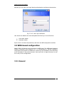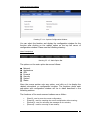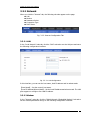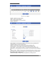
1
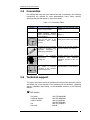
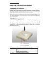
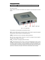
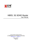
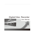
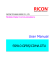
H7921 3G Router User Manual Hongdian Corporation F5~6, Building 14, Shangsha Science & Tech Park, Binhe Blvd., Shenzhen, China Tel: +86-755-88864288 Fax: +86-755-83404677 Postal Code: 518048 www.hongdian.com www.mdtu.com Copyright © 1997-2012 Release 1.0.2 Manual Declaration Copyright All information in this user manual is protected by copyright law. Whereby, no organization or individual shall copy or reproduce the whole or part of this user manual by any means without written authorization from Shenzhen Hongdian Technologies Corporation. Trademark , , Hongdian, GPRS DTU, MDTU, Hongdian Technologies, Shenzhen Hongdian and Galaxy are the trademarks and logos of Shenzhen Hongdian Technologies Corporation. Other trademarks and logos mentioned in this manual belong to other organizations related. Shenzhen Hongdian Technologies Corporation does not own the rights of other trademarks and logos. 2 H7921 3G Router User Manual CONTENTS CHAPTER 1 ABOUT THIS MANUAL ..............................................................4 1.1 Purpose....................................................................................................4 1.2 Applicable scope.....................................................................................4 1.3 Version information................................................................................4 1.4 Convention ..............................................................................................5 1.5 Technical support...................................................................................5 1.6 Acronym and term .................................................................................6 CHAPTER 2 Product Introduction ..................................................................9 2.1 Galaxy 3G overview ..................................................................................9 2.1.1 Product appearance ........................................................................9 2.1.2 Other Accessories..........................................................................11 2.1.3 Device installation .........................................................................11 2.2 Function and features.............................................................................12 2.2.1 Hardware function.........................................................................12 2.2.2 Software function ..........................................................................13 2.3 System application ..................................................................................13 CHAPTER 3 ROUTER CONFIGURATION .....................................................15 3.1 Overview...................................................................................................15 3.2 Connection settings.................................................................................15 3.2.1 Environment requirements ..........................................................15 3.2.2 Connection method.......................................................................16 3.2.3 Network configuration ..................................................................18 3.2.4 System login...................................................................................22 3.3 WEB-based configuration.......................................................................23 3.3.1 General .......................................................................... 23 3.3.2 Network ......................................................................... 25 3.3.3 Applications ....................................................................................31 3.3.5 Forward...........................................................................................44 3.3.6 Security ...........................................................................................46 3.3.7 System ............................................................................................49 3.3.8 Status ..............................................................................................54 CHAPTER 4 FREQUENTLY ASKED QUESTIONS (FAQ)................................56 4.1 Fault analysis ...........................................................................................56 APPENDIX: SOFTWARE UPGRADE DESCRIPTION......................................58 H7921 3G Router User Manual Chapter 1 About This Manual This chapter briefly describes the function and role the this user manual has had, and gives the readers the information on how to read this user manual as the ® best guideline while Hongdian H7921 series products are installed and operated. 1. 2. 3. 4. 5. 6. 1.1 Purpose Applicable scope version information Convention Technical support Acronyms and terms Purpose This user manual is developed mainly on the basis of H7921 V1.0, and is used as the guideline while Hongdian tested. 1.2 ® H7921 series products are installed and Applicable scope This user manual is applicable to those who have certain knowledge and skills on the computer communication network, electronic technology, and network device management and other relevant personnel that need to use Hongdian® H7921 Router. Applicable product version: H7921 V1.0 version 1.3 Version information ® Hongdian H7921 Router may be adjusted functionally and updated technically from time to time according to the needs of the market and users. Meanwhile, the developers may not find out the incorrect content in this user manual in time due to various reasons. The above cases may cause change of the version of this user manual. The table below records the version information and revision reason of this user manual in different periods for the reader’s reference. Table -1.1: Revision History Version Revised by Involved dept. Revised on V1.0.0 Caradoc Liu 2010-2-23 Beta V1.0.1 Caradoc Liu 2010-3-17 Release V1.0.2 Bobby 2012-7-10 Description Beta H7921 3G Router User Manual 1.4 Convention For reading and using this user manual fast and conveniently, the following conventions are reached for some abbreviations, icons, notes, security warnings and tips that appear in this user manual: Table -1.2: Convention Table Item H7921 H7000 1.5 Description Note ® Appears in Chapter 2 the process after Means Hongdian Wireless DDN Communication System series products Means tips or experiences that can save time in the installation and testing process Appears in Chapter 2 the process after Prompts the users or relevant readers to remember some important information or parameters descriptions Appears in the use and operation process in the this user manual Warning: e.g. temperature, voltage etc. improper unstable Generally appears in the product introduction and installation description process in this user manual Caution: informs the users of the invalid or improper operation in the operation and testing process. Appears in the description process beyond Chapter 1 in user manual Means Hongdian H7921 3G Router series products ® Appears in the installation and testing process in this user manual Technical support To help the users fast resolve the problem occurring in their operation process and obtain the correct solution of the problems on the hardware, operating system, installation and testing, we are available anytime in the following manner: Call service: Tel (sales) Technical support: 24Hours hotline Fax Post code +86-755-88864288 +86-755-88864298 +86-13316996093 +86-13672886484 +86-755-83404677 518048 5 H7921 3G Router User Manual E-mail service: Technical support: Service [email protected] [email protected] Website and BBS service: Website: BBS: 1.6 www.hongdian.com http://www.mdtu.com/forum/default.asp Acronym and term In this user manual, the following acronyms and terms are used: APN Access Point Name APP Application ATM Asynchronous Transfer Mode ATM Auto Table Machine AuC Authentication Centre BG Border Gateway BGP Border Gateway Protocol BSC Base Station Controller BSCC Base Station Control Connection BSS Base Station System BSSGP BSS GPRS Protocol BTS Base Transceiver System CDMA Code Division Multiple Access CDR Call Detail Record CGF Charging Gateway Function CSD Circuit Switch Data DDN Digital Data Network DDP DTU DSC Protocol DHCP Dynamic Host Configuration Protocol DNS Domain Name System DSC Data Service Center DTU Data Terminal Unit EGP External/Exterior Gateway Protocol EIGRP External/Exterior Internet Group Routing Protocol EMC Electro Magnetic Compatibility ESP Electro Static Precautions 6 H7921 3G Router User Manual ETSI European Telecommunications Standards Institute GGSN Gateway GPRS Support Node GMSC Gateway MSC GPRS General Packet Radio Service GSM Global System for Mobile Communications GSN GPRS Support Node GTP GPRS Tunneling Protocol GTP-id GTP Identity HLR Home Location Register HSCSD High Speed Circuit Switch Data IGMP Internet Group Management Protocol IGRP Internet Gateway Routing Protocol IN Intelligent Network IP Internet Protocol IPv4 IP version 4 IPv6 IP version 6 IPSEC IP Secure Protocol ISDN Integrated Services Digital Network ISP Internet Service Provider L2TP Layer 2 Tunneling Protocol LA Location Area LLC Logical Link Control MAP Mobile Application Part MDNS Mobile Domain Name System MDTU Mobile Data Terminal Unit MIB Management Information Base MS Mobile Station MSC Mobile Switching Center MT Mobile Terminal MTBF Mean Time Between Failure MTTR Mean Time To Recovery N/A Not Applicable NAS Network Access Server NAT Network Address Translation NTP Network Time Protocol O&M Operations & Maintenance PAP Password Authentication Protocol 7 H7921 3G Router User Manual PCF Packet Control Function PDP Packet Data Protocol PDN Packet Data Network PDSN Packet Data Service Node PLMN Public Land Mobile Network POS Point of Sales PTM-G Point-to-Multipoint Group Call PTM-M Point-to-Multipoint Multicast QoS Quality of Service RA Routing Area RADIUS Remote Authentication Dial In User Service RIP Routing Information Protocol RSC Register Service Center RTOS Real Time Operating System RTP Real-time Transport Protocol RTU Remote Terminal Unit RSVP Resource reSerVation Protocol SCADA Supervisory Control and Data Acquisition SGSN Serving GPRS Support Node SIM Subscriber Identify Module SMS Short Message Service SMSC Short Message Service Center SNMP Simple Network Management Protocol STK SIM Tool Kits TCP Transmission Control Protocol TDMA Time Division Multiple Access TMN Telecommunication Managed Network UDP User Datagram Protocol UIM User Identify Module UMTS Universal Mobile Telecommunication System USSD Unstructured Supplementary Service Data UTK UIM Tool Kits VLR Visitor Location Register WAN Wide Area Network WAP Wireless Application Protocol WDDN Wireless Digital Data Network 8 H7921 3G Router User Manual CHAPTER 2 Product Introduction 2.1 Galaxy 3G overview Combining with the third generation of mobile communication technology and WLAN technology, Galaxy 3G mobile network data communication terminal product is designed as a high-tech 3G product upon the needs of users. It can provide data communication service for these users at any time and in any place. Galaxy H7921 3G Router is characterized with excellent transmission reliability and a wide range of applicability. It is the ideal choice for various sectors as a special data communication system. 2.1.1 Product appearance The appearance, installation position and dimension of the router are shown below. In consideration of different application sites, the installation accessories are provided on both sides. You can put it on table directly without using these accessories; while in industry, finance, public utilities and other related application sites, it is generally required to fix it with the installation accessories to comply with the industrial application requirements. LED SIM card socket Fig. 2.1.1-1: Front Panel The indicators on the front panel are described as the table below: Indicator LAN: NET: State Description It lights shows there is a LAN connect, flash shows it has data communication. Indicate the status of module. H7921 3G Router User Manual SYSTEM: It lights when router works normally. Back panel interface Galaxy H7921 3G Router’s all interfaces are designed on the back panel as shown below: COM LAN POWER RESET ANT Fig. 2.1.1-2: Back Panel The interfaces on the back panel are described as below: ANT:Antenna (SMA negative terminal) interface, which is able to match with standard short antenna, vehicular antenna or directional antenna; RESET:Reset button used for restoring the default parameters. DC:DC power supply interface. (Be sure to check if the voltage of power supply is consistent with the label on the router) RJ45:10/100BaseT self-adapting Ethernet interface; COM:Serial interface (RS-232) used for receiving and dispatching the data of serial interfaces of terminal equipment or setting the console. Its application is dependent on the working modes. For instance, under the CONSOLE mode, press the Spacebar of PC connected with the serial interface to display the configuration state when the system is powered up. Otherwise, the system will start the communication state normally. 10 H7921 3G Router User Manual 2.1.2 Other Accessories For safe transportation purpose, Galaxy H7921 3G Router should be packaged properly. Pease keep the packaging materials well after the package is opened for future use in case of re-transportation. Standard fittings Galaxy H7921 3G device 1 (packaged upon the order conditions) 3G antenna 1 +12V power adapter 1 User manual 1 (CD-ROM) Certificate of conformity and warranty card 1 Mounting and securing fittings 1 pair Optional accessories 1.5m RJ45 cable 1 Check the amount of articles after open-package. For the specific amount, please refer to the user order contact. 2.1.3 Device installation Note: Please don’t install Galaxy H7921 3G Router while it is powered. 2.1.3.1 Environment requirements The system can be used under the following conditions: Voltage : +5VDC~26VDC Power Consumption: Peak working Current: 240mA@+12VDC In time of idling: 40mA@+12VDC Operating Ambient Temperature: -20~+60ºC Storage Temperature: -30~+70ºC Relative Humidity: <95% (no condensation) Galaxy H7921 3G Router can be placed in office, on wall or installed or fixed in any places, without special wiring and heat radiating requirements. To ensure the long-term and stable operation of system, grounding measures and dust-proof measures should be taken on power supply, keep ventilation and a proper room temperature. Caution: 1. This system cannot be used under severe condition, such as acid/alkali environment, strong magnetic field etc. In such environments, the normal operation of this system cannot be ensured. Any physical damage will not be included in the quality guarantee; 2. This product is a Class-A information product, which may cause radio interference in living environment when being used. In this case, the users are required to take some proper measures. 11 H7921 3G Router User Manual 2.1.3.2 Wiring RJ-45 - Ethernet interface Standard 10/100BaseT Ethernet switch port, self-adaptive DC - power supply interface, Galaxy H7921 3G router’s power supply is generally +12VDC ANT - antenna interface The standard 5OΩ/SMA RF connector (female) is applied. In the environment of some industrial applications, the lightning protection measures should be taken. You can install the lightning protection device between this connector and antenna. Note: 1. 2. 3. 4. Keep this product away from any heating source; Don’t place this product in dusty or humid environment; Keep it away from some possible interference sources such as metal wall, microwave oven etc; To ensure that Wi-Fi network signal is received well, please pay attention to the position and the angle of antenna. Don’t place antenna inside the shielded metal case. 2.2 Function and features Galaxy series 3G mobile data communication terminal product features platform and modularization design. Upon the different demand from the users, the platform extension, modem combination and clipping are carried out to comply with various application demands of different clients. Combination of Broadcom hardware platform with Linux-based GOS (Galaxy Operation System) software platform is its core advantage. The features of full-function Galaxy 3G mobile data communication terminal product include: 2.2.1 Hardware function z SYSTEM, NET, LAN indicators z Factory default configuration restoration button z Antenna interface: 50Ω/SMA negative end z Serial data interface (DB9): RS-232(DCE) z Serial data interface rate: 300 to 230,400 bits/s z Ethernet interface: one 10/100BaseT/RJ45 self-adapting z Configuration interface: WEB/Telnet or RS-232 12 H7921 3G Router User Manual 2.2.2 Software function Supporting HSUPA/HSDPA/EDGE/GPRS or EVDO/CDMA 1x Built-in DHCP Service Supporting DMZ host computer Supporting DDNS Supporting static routing list Supporting IP address and port filtration Supporting monitor mobile network traffic quality. WEB/Telnet Management Local Firmware Upgrading/ Configuration Backup System Log Server 2.3 System application Multiple application modes for H7921 3G Router are described as follows: z Application Mode One: Application in video monitoring The center-to-multipoint network generally needs to be adopted for the application mode of video monitoring. Please connect and install the router and network camera according to the following schematic diagram. Furthermore, other Ethernet interface equipment can be also connected at the video monitoring site for built-in Ethernet exchangers: 13 H7921 3G Router User Manual Diagram 2.3-1: Schematic diagram for video application z Application Mode Two: Application in SoHo There is one built-in 10M/100M self-adapting fast Ethernet port within H7921 3G Router, which greatly facilitates SoHo user getting access to the internet. Diagram 2.3-2: Schematic diagram for application in SOHO 14 H7921 3G Router User Manual z Application Mode Three: Application in banking business H7921 3G Router is able to be connected to the target machine and other network devices at the same time. Take ATM network in the banking business for example. ATM machine needs to be connected to the host computer of bank, and at the same time, it is also connected to the video camera, and thereby monitoring the conditions around ATM machine. Diagram 2.3-3: Schematic diagram for application in banking business Chapter 3 Router Configuration 3.1 Overview Galaxy H7921 3G Router features built-in WEB interface configuration, management and debugging tools. Before using Galaxy H7921 3G Router, users should configure relate parameters; during using, you can freely change related parameters and perform software upgrade and simple test etc. When you enter Galaxy H7921 3G Router built-in WEB configuration interface, you can set and manage its parameters as described below. 3.2 Connection settings 3.2.1 Environment requirements When you want to use Galaxy H7921 3G Router, a computer and a UIM/SIM card should be prepared according to the following requirements: 15 H7921 3G Router User Manual Computer with Ethernet card and TCP/IP protocol 1. 2. IE6.0 or higher Support 1024x768 resolution display 3.2.2 Connection method For your convenient use, we recommend you plug your SIM/UIM card into H7921’s card slot before your configuration. Then power on H7921 and begin your configuration. Upon the actual conditions, connect and configure Galaxy H7921 3G Router by the following two methods: Note: You can configure H7921without any card, but you may not connect to the internet until you insert a SIM/UIM card. Warning: Never pull or plug your SIM/UIM card when H7921 is power on. Your card may be damaged. Warning: The metal casing of H7921 3G Router has to be well connected to the ground so as to ensure the router a safe, stable and reliable operation. 3.2.2.1 Ethernet direct connection method Using Ethernet cable with RJ-45 connector, directly connect the computer to one of LAN ports on Galaxy H7921 3G Router as shown in the figure below: Fig. 3.2.2.1: Wiring Method 1 Note: Galaxy H7921 3G Router’s LAN port is designed with self-adaptive cross connect technology, so the straight-through cable or cross cable can be both applied to connect devices for communication. 16 H7921 3G Router User Manual 3.2.2.2 LAN connection method When it is required to connect Galaxy H7921 3G Router to local network through HUB or switch, connect the hub or switch out-link port with any one of its switch ports as shown in the figure below. Fig. 3.2.2.2: Wiring Method 2 3.2.2.3 Serial port connect COM – serial interface COM serial communication interface is a standard RS-232(DCE) interface with DB9 terminal (negative terminal). It can be used for the configured console (CONSOLE) or normal communication interface. The cables of RS-232(DCE) interface are defined as follows: PIN Name 1 2 3 4 5 6 7 8 9 CD RXD TXD DTR GND DSR RTS CTS RI DB-9 connector (DCE-negative terminal) Description Direction of signal --Æ Carrier Detect Å-Received Data --Æ Transmitted Data Å-Data Terminal Ready Signal Ground --Æ Data Set Ready Å-Request To Send --Æ Clear To Send --Æ Ring Indicator Remark s RJ-45 – Ethernet Interface 17 H7921 3G Router User Manual Self-adapting (Version 2.0 or above) standard 10/100BaseT Ethernet switching interface ANT – antenna interface The standard 5OΩ/SMA radio-frequency connector (negative terminal) is adopted for use. In addition, the lightning-proof measures need to be adopted for some operating conditions, so you may place a lightning protection device between the connector and the antenna. Attention: 1. 2. 3. 4. The products shall be far away from any heating device; Don’t place the products in the dusty or wet environment; The products shall be far away from some potential interference sources, like the metal wall, and micro-wave oven, etc; Pay attention to the position and angle of antenna to ensure it works well. Don’t place the antenna in the shielding metal box. 3.2.3 Network configuration After the configuration environment is connected well as one of the connection methods, the local configuration computer IP address and other parameters should be set. Take the LAN connection method as an example to describe the network configuration procedure shown as below. 1. Configuration computer setting First, enter the computer control panel of the selected computer, find “Network Connections” icon and double click it to enter, select “Local Area Connection” corresponding to the network card on this page. Refer to the figure below. Fig. 3.2.3-1: Computer Local Connection Configuration 18 H7921 3G Router User Manual Enter (double click or right click) the “Local Area Connection”Æ“Property (R)” and enter the interface shown in the figure below: Fig. 3.2.3-2: Computer Local Connection Configuration Select the “Internet Protocol (TCP/IP)”, click the “Properties”, and enter the interface as below: 19 H7921 3G Router User Manual Fig. 3.2.3-3: TCP/IP Properties Configuration Method 1: general configuration This method will temporarily interrupts the communication between the computer under configuration and LAN, and the specific parameter configuration is shown as below: IP address: 192.168.8.* (*indicates any integral between 2 to 254) Subnet mask: 255.255.255.0 Default gateway: 192.168.8.1 Remember: Galaxy H7921 3G Router LAN port factory default parameter: IP address: 192.168.8.1; Subnet mask: 255.255.255.0 Galaxy H7921 3G Router factory default login parameter: Management interface login IP address: 192.168.8.1 Login name: admin Login password: admin Method 2: advanced configuration If you don’t want to interrupt local PC LAN communication and configure Galaxy H7921 3G Router when the former network configuration exists, it is required add route (IP). 20 H7921 3G Router User Manual The configuration operation is shown as below: Click the “Advanced (V)…”button in Fig. 3.2-5 to enter the interface as below: Fig. 3.2.3-4: Advanced TCP/IP Properties Configuration Click the “Add (A)”button under the “IP address (R)”, and fill in the IP address that you want to add: Fig. 3.2.3-5: Add TCP/IP Address After the configuration is completed, click the “Add”. By now the computer has a route to Galaxy H7921. 21 H7921 3G Router User Manual Note: As shown in Fig. 3.2-3, “Default gateway” depends on whether the configuration computer connects with Internet through original local network configuration. If Internet is accessed through original local network, the default gateway setting does not need to be modified; if Galaxy H7921 3G Router + is used, you need to modify the default gateway and configure it as Galaxy H7921 3G Router’s default LAN IP address 192.168.8.1. 2. Network check Step 1: IP configuration check Use the command of ipconfig to check whether the IP address is correctly set or added. You can enter DOS mode and key-in command: ipconfig, for instance: C:\>ipconfig Windows IP Configuration Ethernet adapter local connection: Connection-specific DNS Suffix. : Auto configuration IP Address . . .: 192.168.8.7 Subnet Mask . . . . . . . . . . .: 255.255.255.0 Default Gateway . . . . . . . . . : 192.168.8.1 Step 2: connectivity check After the configuration is completed, you can check the connectivity between it and Galaxy H7921 3G Router by ping command. Key-in ping command in system command line: Ping 192.168.8.1 If the following information appears: Pinging 192.168.8.1 with 32 bytes of data: Reply from 192.168.8.1: bytes=32 time=2ms TTL=64 Reply from 192.168.8.1: bytes=32 time=2ms TTL=64 By now, it means that the configuration computer has been connected to the router. You can carry out configuration operation on it. 3.2.4 System login Open the IE browser, and input http://192.168.8.1/ in address bar, as shown below: Fig. 3.2.4-1: Web Login 22 H7921 3G Router User Manual And then you can enter user login identity authentication interface as shown below: Fig. 3.2.4-2: User Login Verification User should use default user name and password when log in for the first time: User name: admin Password: admin Input correct user name and password, and enter the WEB configuration interface. 3.3 WEB-based configuration Galaxy H7921 3G Routers can be configured in WEB mode. The WEB-based operation features visualization and simplicity, so it is recommended to perform parameter configuration and operation in WEB mode. Connect the PC and Galaxy router according to the description in the previous section. Start up IE (6.0 or higher) browser on your PC to carry out the configuration. 3.3.1 General 23 H7921 3G Router User Manual Drawing 3.3.1-1: System Configuration Window You can select the function and display the configuration window for the function after clicking on the related option on the top left corner of configuration window. Please see the following drawing: Menu Descriptions Drawing 3.3.1-2: Main Option Bar The options on the main option bar are as follows: z z z z z z z Network Applications VPN Forward Security System Status Move the mouse pointer onto any option, and click on it to display the related sub-options or configuration window. The functions about each sub-option and configuration window will be in detail described in the following sections. The functions of the most common buttons are as follow: 【Save】: used to save the current configuration; 【Cancel】: used for canceling the current configuration without saving; 【Refresh】: used for refreshing the messages on the window; 【Return】: used for returning to last window; 24 H7921 3G Router User Manual 3.3.2 Network When you click the “Internet” tab, the following sub-tabs appear on the page: LAN Modem Parameter Select Connection Type DHCP Sever Fig. 3.3.2: Internet Configuration Tab 3.3.2.1 LAN In the “Local Network” main tab, click the “LAN” sub-tab to set the LAN port and enter the following configuration interface: Fig. 3.3.3.1: LAN Configuration In this interface, you can set the host name, local IP address and its subnet mask: 【Host Name】: Set the router’s host name. 【Local IP Address/Subnet Mask】: Set the local IP address and subnet mask. The LAN port supports to configure four LAN IP address. 3.3.2.2 Modem In the “Internet” main tab, click the “Mobile Network (Embedded Modem)” sub-tab to set the modem parameters and go to the following configuration interface: 25 H7921 3G Router User Manual Fig. 3.3.2.1-1: Modem 【Mod】: Modify the current settings. 【Del】: Delete current settings. 【En】: Enable/disable the current settings. 【Add】: Add SIM ID. 【Auto-Dialup】: Set the account number of 3G network service provided by ISP. 【Interface Name】: Set the SIM card name. 【APN】: Set the APN of the internet access service provided by ISP. 【Service Code】: Set the name of 3G network service provided by ISP. 【User Name】: Set the account number of 3G network service provided by ISP. 【Password】: Set the password of account number of 3G network service provided by ISP. 【Network Type】: DEFAULT means router will obey default option to choose network; AUTO means router will choose available network automatically; Other options mean router will use certain network only. 【Advanced setting】: Configure advanced parameter by dialing protocol. 26 H7921 3G Router User Manual Note: This feature is special. It’s used to match with Parameter Select feature together. For example, if need to communicate with two different data servers via VPN tunnel. There is a priority for two VPN tunnel. So each tunnel need to bind one SIM ID. In the “Advanced setting” tab, it contains “PPP Advanced Settings” & “Internet Connection Type Settings”, the interface of “PPP Advanced Settings” is as below: 27 H7921 3G Router User Manual Fig. 3.3.2.1-2: PPP Advanced Settings Considering the difference of mobile network authorization, the Point to Point Protocol connection should be compatible with different network. Advanced setting is used for the PPP special setting. Click “PPP Advanced Setting” button to start settings. Normally, it is not required to change the setting for most of networks and applications. If it is necessary, you need to be cautious in setting PPP Advanced based on the network environment. For detailed configuration, consult the local mobile operator and carry out multiple trials to achieve the best suitability. 【CHAP, PAP, MS-CHAP, MS-CHAPv2】are negotiation protocol types while PPP dialing. 【Compression Control Protocol negotiation】: Set whether disable Compression Control Protocol negotiation. 0: disable; 1: enable. 【Address/Control compression】: Set whether disable Address /Control compression. 【Protocol field compression negotiation】: Set whether disable protocol field compression negotiation 【VJ style TCP/IP header compress】: Set whether disable Van Jacobson style TCP/IP header compress. 【Connection-ID compression】: Set whether disable the connection-ID compression option in VJ. 【Debug】: Set whether enable the debug log function. 【Use Peer's DNS】: Set whether disable Use Peer's DNS. 【LCP Echo Interval】: Set LCP’s maximum interval time, in second. 【LCP Echo Failure】: Set LCP’s maximum request times. 【MTU】: Set the number of bytes of the maximum transfer unit. 【MRU】: Set the number of bytes of the maximum receive unit. 【local IP】: Set the local IP address. 【Remote IP】: Set the remote terminal’s IP address. 【Other Options】: Users can define their own options here. 3.3.2.3 Parameter Select 28 H7921 3G Router User Manual Fig. 3.3.2.3: Parameter Select Interface Fig. 3.3.2.3-1: Parameter Select Interface 【Status】Enable/disable the parameter select feature. 【Rule Name】Set the rule ID from 0 to 9. 0 is the prepreerence. 【Interval】: Set the check interval. 【Retry Times】: Set the check times. 【Running Timeout】: Set the active time for current rule. Once the time is over, it will switch to the next rule. 【Interface Name】: Select the interface name for check. 【Check method】: Select the check mode for state or ICMP. State mode means router will automatically check the specified interface as the interval and retry times. Once the status is failed, router will automatically switch rule from current rule. 29 H7921 3G Router User Manual ICMP mode means router will automatically check the specified destination IP as the interval and retry times. Once the ICMP is failed, router will automatically switch rule from current rule. 3.3.2.4 Connection Type In the “Internet” main tab, click the “Internet Connection Type” sub-tab to set the internet connection type. Select the internet connection type from the “Connection Type” drop-down menu: “Modem” and “Custom”. Below, we will describe the configuration in different modes: Fig. 3.3.2.4: Modem configuration Interface 【Work Mode】: Default mode for gateway. It also supports route mode. 【Default Route】: Select interface name as the default route. 【DNS Type】: Specify interface or customize DNS. 【Interface Name】: If specify interface for DNS type, need to select interface name. 3.3.2.5 DHCP server In the “Local Network” main tab, click the “DHCP Server” sub-tab to set the DHCP server parameters and go to the following configuration interface: 30 H7921 3G Router User Manual Fig. 3.3.2.5: DHCP Configuration Interface The configuration parameters include: 【DHCP Server】: Set whether enable the DHCP server function: Enable/Disable. 【IP Pool】: Set the range of the DHCP dynamic address pool as the default bro interface or customize the IP address range. 【Gateway Type】: Set the gateway to client assigned by DHCP: Default, Static, as same as router’s gateway. 【DNS Type】: Specify interface or customize DNS. 【Lease Time】: Set the lease time, namely the time that the client uses the assigned IP 【Add】: Map the DHCP client’s MAC address with IP. 3.3.3 Applications When you click the “Applications” tab, the following sub-tabs appear on the page: DDNS Timing Operation Trigger On-line Data ICMP Check DTU Interface Check 31 H7921 3G Router User Manual Fig. 3.3.3: Applications Configuration Tab 3.3.3.1 ICMP Check In the “Applications” main tab, click the “ICMP Check” sub-tab to set the ICMP Check parameters and go to the following configuration interface: Fig. 3.3.3.1: ICMP Check Interface Trigger On-line Data parameters include: 【Destination IP or Domain】: Set whether enable the ICMP Check Service IP and domain name. 【Retry Times】: Set how many times ICMP pack will be send. 【Normal Interval】: Set the interval of ICMP packs. 【Source Type】: Set ICMP package’s source IP address. 【Failed Interval】: Set how many seconds ICMP check will fail if no response. 3.3.3.2 Interface Check In the “Applications” main tab, click the “Interface Check” sub-tab to set the interface parameters and go to the following configuration interface: 32 H7921 3G Router User Manual Fig. 3.3.3.2: Interface Check 【Interface Name】: Set which interface will be check. 【Flow Direction】: the way to check data flow. 【Check Interval】: Set the interval of check. 【Retry Times】: Set the check times. 3.3.3.3 DDNS The router is designed with DDNS (Dynamic Domain System) function which can make others to search the dynamic IP address by internet domain. In the “Application” main tab, click the “DDNS” sub-tab to set DDNS parameters and go to the following configuration interface: 33 H7921 3G Router User Manual Fig. 3.3.3.3: DDNS Configuration Interface DDNS configuration parameters include: 【DDNS Server】: Set whether enable DDNS service function: Enable/Disable. 【Service Provider】: Select the DDNS service provider that router currently supports. Domestic DDNS service provider: 88IP (www.88ip.net), 3322 (www.3322.org); oversea DDNS service provider: DNSEXIT (www.dnsexit.com), ZONEEDIT (www.zoneedti.com), CHANGEIP (www.changeip.com), Dyndns (members.dyndns.org); you can also select”custom” and choose your own DDNS service provider if it is not listed above. 【Server Port】: Set the port number of the DDNS server provided by the service provider. The default port number is 80. 【User Name】: Set the legal user name of the DDNS service registered in the service provider. 【Password】: Set the password of the legal user name of the DDNS service registered in the service provider. 【User Domain】: Set the domain of the DDNS service provided by the service provider. 【Update Interval】: Set the interval of the DDNS client obtains new IP, in second. 3.3.3.4 DTU In the “Applications” main tab, click the “RTU” sub-tab to set the DTU parameters and go to the following configuration interface: 34 H7921 3G Router User Manual Fig. 3.3.3.4: DTU Interface DTU parameters include: 【DTU Service】: Set whether enable the DTU Service. 【Work Mode】: Work as a Server or a Client. Client will register to server automatically. 【Local Port】: Set the receive port if work mode is server. 【Protocol:】: Select the protocol used to transmit. 【Received Packet Max Length】: Set the max length of received packet, this value must smaller than 1024. 【Received Timeout】: Set the timeout for receiving data. 【RS232 Data Timeout】: Set the timeout for RS232 data. 【Rs232 Setting】: Set parameters of Rs232 port, please set these according to your device’s Rs232 port parameters. 3.3.3.5 SNMP In the “Applications” main tab, click the “SNMP” sub-tab to set the Timing Operation parameters and go to the following configuration interface: 35 H7921 3G Router User Manual Fig. 3.3.3.5 SNMP 【SNMP Sevice】: Set whether enable the DTU Service. 【Port】: Set the SNMP port. 【Community】: Set the SNMP community. 3.3.3.6 M2M In the “Applications” main tab, click the “M2M” sub-tab to set the Timing Operation parameters and go to the following configuration interface: Fig. 3.3.3.6 M2M 36 H7921 3G Router User Manual 【M2M Sevice】: Set whether enable the M2M Service. 【Server IP or Domain】: Set the server IP or domian. 【Server Port】: Set the server port. 【Login Times】: Set login max times. 【Heartbeat Interval】: Set the heartbeat interval for M2M connection. 【Retry Times】: Set the SNMP community. 【Task Failure Time】: Set the SNMP community. 3.3.3.7 Timing In the “Applications” main tab, click the “Timing” sub-tab to set the Timing Operation parameters and go to the following configuration interface: Fig. 3.3.3.7: Time Interface The configuration parameters include: 【Add】: Add the Timing Operation operated at certain time. 【Status】: Set whether enable the Timing Operation. 【Task Name】:Set the task name for timing operation. 【Task Type】: Select the task type like reboot, dialup and dialdown. 【Set Time】: We have five types of time: Clock, day, and week. All you need processing the time is to fill each type with valid value. When setting, for each type of time, you need to split the different value with ",", and you can use "xx-xx" to represent a period of time. 37 H7921 3G Router User Manual 3.3.3.8 Wake Up In the “Applications” main tab, click the “Wake Up” sub-tab to set the Trigger On-line Data parameters and go to the following configuration interface: Fig. 3.3.3.8: Wake Up Interface Wake Up parameters include: 【Wake Up Service】: Set whether enable the Wake Up. 【Wake Up Method】: Set wake up method via phone&data or phone. 【Offline Method】: Set the offline method for timeout or idle. 【Online Time】: Set the online time. 【Phone Number】: Set the phone number of wakeup. 【Task Type】: Set wakeup task type for dialup, dialdown or reboot. 3.3.4 VPN When you click the “VPN” tab, the following sub-tabs appear on the page: 38 H7921 3G Router User Manual Fig. 3.3.4: VPN Interface When you click the “VPN” tab, the following sub-tabs appear on the page: VPDN Tunnel IPSec 3.3.4.1 VPDN Click the “Add” tab; the following sub-tabs appear on the page: Fig. 3.3.4.1-1: VPDN Interface 39 H7921 3G Router User Manual Fig. 3.3.4.1-2: VPDN Interface 【VPDN Service】: Enable/disable the VPDN Service. 【Interface Name】: Set the VPDN name. 【Protocol】: Select the VPN protocol for PPTP or L2TP. 【Server IP or Domain】: Set the VPN server IP or domain name. 【Username】: Set the username. 【Password】: Set the password. 【Advanced Settings】: Set the advanced setting like CCP and so on. 3.3.4.2 Tunnel Click the “Add” tab; the following sub-tabs appear on the page: Fig. 3.3.4.2-1: Tunnel Interface 40 H7921 3G Router User Manual Fig. 3.3.4.2-2: Tunnel Interface 【IP Tunnel Service】: Enable/disable the tunnel service. 【Tunnel Name】: Set the tunnel name. 【Tunnel Mode】: Select tunnel mode for ipip or GRE 【Local Virtual IP】: Set the local virtual IP of tunnel. 【Interface Type】: Select interface type of tunnel for interface or static IP. 【Local Extern Interface】: Select the local extern interface. 【Peer Extern IP】: Set the peer extern IP. 3.3.4.3 IPsec 41 H7921 3G Router User Manual Fig. 3.3.4.3-1: IPsec Interface Click the “Add” tab; the following sub-tabs appear on the page: Fig. 3.3.4.3-2: IPsec Interface 【Select】: Select the IPSec phase 1. 【Policy Name】: Set the policy name in IPSec phase 1. 【Initial Mode】: Select IPsec mode for main mode or aggressive mode. 【Encrypt】: Select IPSec encryption arithmetic. 【Hash】: Select IPSec Hash arithmetic. 【Authentication】: Select IPSec authentication mode for pre-share key. 【Pre Share Key】: Set the pre-share key. 【Match Identify】: Set the match Identify. 【IKE Lifetime】: Set the IKE lifetime. 【Group Name】: Select the group for group 1024 or group 1536. 【DPD Service】: Enable/disable DPD service. 【DPD Delay】: Set the DPD delay time. 【DPD Timeout】:Set the DPD timeout. 42 H7921 3G Router User Manual Fig. 3.3.4.3-3: IPsec Interface 【Select】: Select the IPSec phase 2. 【Policy Name】: Set the policy name in IPSec phase 1. 【Encryption Protocol】: Select 【Encrypt】: Select IPSec encryption arithmetic. 【Hash】: Select IPSec Hash arithmetic. 【PFS】: Enable/disable PFS. 【Lifetime】: Set the lifetime in phase 2. 【Transport Mode】: Select transport mode for transport mode, tunnel mode or auto negotiation. 【Local Subnet】: Set the local subnet. 【Remote Subnet】: Set the remote subnet. 43 H7921 3G Router User Manual Fig. 3.3.4.3-4: IPsec Interface 【Select】: Select the IPsec setting. 【Interface Name】: Set the IPSec name. 【Match Phase 1】: Select IPSec policy name for phase 1. 【Match Phase 2】: Select IPSec policy name for phase 1. 【Destination IP or Domain】: Set the peer IP or domain name. 【Encrypt Interface】: Select the encryption interface. 3.3.5 Forward When you click the “Forward” tab, the following sub-tabs appear on the page: NAT & DMZ Static Route Fig. 3.3.5: Forward Tab 3.3.5.1 Nat In the “Forward” main tab, click the “NAT” sub-tab to set the route mode, NAT and DMZ functions and go to the following configuration interface: 44 H7921 3G Router User Manual Fig. 3.3.5.1-1: NAT Interface Select the “NAT” option to go to the following configuration interface: Fig. 3.3.5.1-2: NAT Interface 【Select】: Select NAT or MASQ. 【Chain】: Select the NAT mode. 【Protocol】: Select the protocol for NAT mode. 【Source Address】: Set the source IP address. 【Replace Address】: Set the replace IP address. 3.3.5.2 Static Route In the “Forward” main tab, click the “Static Route” sub-tab to set the static route parameters and go to the following configuration interface: 45 H7921 3G Router User Manual Fig. 3.3.5.2-1: Static Route Configuration Interface To add the static route, click the “Add” button and go to the following configuration interface: Fig. 3.3.5.2-2: Static Route Configuration Interface 【IP Address/Mask】: Configure the destination network address and mask of this static route. 【Gateway Type】: Select gateway name for interface or static IP address. 【Gateway】: Select gateway interface or set the gateway static IP address 3.3.6 Security When you click the “Security” tab, the following sub-tabs appear on the page: IP Filter Domain Filter MAC Filter 3.3.6.1 IP Filter Click the “Add” to go to the following configuration interface: 46 H7921 3G Router User Manual Fig. 3.3.6.1-1: IP Filter Interface You can choose filter type here: IP filter rules for Basic or Expand Select the “Basic” to go to the following configuration interface: Fig. 3.3.6.1-2: IP Filter Interface The configuration parameters include: 【Type】: Basic type is based on IP address filter. Expand type is based on IP address and port filter. 【ID】: Set the identification of the filter rule, the ID is available from 2000 to 2699. 【Default Action】: Accept means permit the added IP address and port. Drop means deny the added IP address and port. Generally, we need to add the rule for deny at first. 【Protocol】: Select the protocol for filter rule. 【Source Type】: Custom means you might specify the source IP or IP segment for permit or deny. Any means all IP addresses are permitted or denied as you configured. Host means the only IP address is permitted or denied. 【Source IP】: Set the source IP address of the filter rule, may be defined IP address or one IP segment. Specially, you must configure the initial IP of IP segment. 47 H7921 3G Router User Manual 【Wildcard Bits】: Configure the wildcard for source IP address or IP segments. 【Destination IP】: Set the source IP address of the filter rule, may be defined IP address or one IP segment. Specially, you must configure the initial IP of IP segment. 【Wildcard Bits】: Configure the wildcard for source IP address or IP segments. 3.3.6.2 Domain Filter Fig. 3.3.6.2: Domain Filter Interface 【Domain Keyword】: Set the domain keyword, e.g. www.google.com. 3.3.6.3 MAC Filter Fig. 3.3.6.3: MAC Filter Interface Click the “Add” to go to the following configuration interface: 48 H7921 3G Router User Manual Fig. 3.3.6.3-1: MAC Filter Interface 【MAC】: Set the the MAC address. 【Default Action】: Select the action mode for accept or drop. 【Filter Mode】: Select the filter mode for input, forward or both. 3.3.7 System When you click the “System Tools” tab, the following sub-tabs appear on the page: Local Log Remote Log Clock Account Network Test Files Fig. 3.3.7: System Tab 3.3.7.1 Local Log In the “System Tools” main tab, click the “Local Log” sub-tab to view the log information and go to the following configuration interface: 49 H7921 3G Router User Manual Fig. 3.3.7.1: Log View Interface Log view settings include: 【Local Log】: Set the type of log to be displayed. After selecting the log type, you can make the following operations: 【View】: Display log in the Log Table. 【Clear】: Clear the log in the Log Table. 【Export】: Export the logs file. Log display: 【Log Table】: Display the system log information in the table. 3.3.7.2 Remote Log In the “System” main tab, click the “Remote Log” sub-tab to set the log function and go to the following configuration interface: 50 H7921 3G Router User Manual Fig. 3.3.7.2: System Log Management Interface The system log configuration parameters include: 【Local Log Status】: Set whether enable local log function: Enable/Disable. 【Remote IP or Domain】: Set the IP address/domain name of the remote server, generally the IP address of the PC that receives the log information. 【Remote Port】: Set the port number of the remote server. Note: For the success of remote log receive, the remote log server must be started. 3.3.8.3 System clock In the “System Tools” main tab, click the “Clock” sub-tab to set the system’s clock function. Time Synch. Type option is the method to synchronize the system time: NTP and Manual. Select the Manual to set the time manually. Select the NTP to go to the following configuration interface: 51 H7921 3G Router User Manual Fig. 3.3.8.3: Clock Configuration Interface The system clock configuration parameters include: 【Status】: Enable/disable the Clock service 【NTP Server IP or Domain】: Set the domain or IP address of the NTP server. 【NTP Sever Backup】: Set the backup NTP server IP address/domain. 【NTP Synch. Interval】: Set the interval of the router making NTP synchronization in successive two times. 【Time Zone】: Set the time zone. 3.3.8.4 Account The router provides the user with the power to modify the password, In the “System” main tab, click the “Account” sub-tab to set the account management function and go to the following configuration interface: 52 H7921 3G Router User Manual Fig. 3.3.7.4: Account Interface The system clock configuration parameters include: 【Account Type】: Set the account based on Web. 【Account Level】:Set the account authority. Admin authority can configure all features. Guest authority just can view all feature. 3.3.7.5 Network Test In the “System” main tab, click the “Network Test” sub-tab. Fig. 3.3.7.4: Account Interface 【Destination】: Set the destination IP address for ping or trace testing. 【Ping】:Select the ping testing for the destination IP address. 【Trace】: Select the trace testing for the destination IP address. 3.3.7.5 File In the “System” main tab, click the “File” sub-tab to upgrade and backup function. 53 H7921 3G Router User Manual Fig. 3.3.7.5: System Reboot Interface 【Firmware Setting】:Upgrade firmware/patch . 【Backup Setting】:Import/export the configuration. 【Save】: Save the current configuration as default. 【Load】: Default the current configuration to default. 【View】: Check the current patch name in the router. 【Delete】:Delete the selected patch. 3.3.8 Status When you click the “Status” tab, the following sub-tabs appear on the page: Base Information LAN Modem Routing Table Fig. 3.3.8: Status Tab Tab description: 【Base Information】: Display the system information. 54 H7921 3G Router User Manual 【LAN】: Display LAN port’s running information. 【Embedded Modem】: Display USB wireless network’s running information. 【Route Table】: Display the route table information. 【DHCP Client】: Display the DHCP Client information. 55 H7921 3G Router User Manual Chapter 4 Frequently Asked Questions (FAQ) 4.1 Fault analysis Fault 1: All indicators are off. Check whether the cables are connected correctly. Meanwhile, check whether the power supply complies with the requirements. Galaxy H7921 3G Router’s label indicates the detailed requirements regarding the power supply voltage. Check whether the power supply voltage is identical with that specified in the label. If the input voltage is correct, but all indicators are off, maybe the device fails. Please contact your sales representative. Fault 2: Unstable phenomenon appears after working for a long time. Check whether the device is overheated. If it is overheated, put the device in a ventilated place. Fault 3: The device doesn’t execute self-checking. Make sure the power supply is correct. Fault 4: How to resolve the problem if the following information appears when you ping the router? Pinging 192.168.8.1 with 32 bytes of data: Request timed out. Such information indicates that error occurs in the installation process. You must check the followings in sequence: 9 Whether PC is connected with Galaxy H7921 3G Router correctly by Ethernet cable? (Note: H7921 Router’s LINK indicator and PC’s Link indicator must be on). 9 Whether PC’s TCP/IP environment is configured correctly? (Note: If H7921 Router’s IP address is 192.168.8.1, PC’s IP address must be 192.168.8.xxx). For more check, click the relevant menu and enter the DOS interface. Type the command: ipconfig, and press the Enter key, for example: H7921 3G Router User Manual C:\>ipconfig Windows IP Configuration Ethernet adapter local connection: Connection-specific DNS Suffix. . . . : IP Address . . . . . . . . . . . . . . . . . . . : 192.168.8.48 Subnet Mask . . . . . . . . . . . . . . . . . : 255.255.255.0 IP Address . . . . . . . . . . . . . . . . . . : 192.168.0.48 Subnet Mask . . . . . . . . . . . . . . . . . : 255.255.255.0 Default Gateway . . . . . . . . . . . . . . : 192.168.0.254 (Type the command: ipconfig? to get more operation help regarding ipconfig command). H7921 3G Router User Manual Appendix: Software Upgrade Description Upgrade tool description and operating instructions Galaxy H7921 3G Router is designed with the platform technology, whose software can be upgraded with the development of the communication and network technology. WEB upgrade: Galaxy H7921 3G Router supports the function of upgrading the firmware directly by importing the upgrade file via the WEB configuration interface. Log in the WEB configuration page by means of entering the router’s IP address (LAN port or WAN port) in the browser’s address bar. Click System Tools -> Firmware Upgrade, to go to the Web firmware upgrade interface. Click the Browse key to find the corresponding upgrade file. Click the Save button to upgrade the firmware. In the process of upgrade, don’t make any other operation to the Web configuration page. Otherwise, the upgrade may fail, which may make the router fails. After the upgrade, this Web page will prompt that the upgrade succeeds or fails. If upgrade fails, you can repeat the above operations again to upgrade the firmware. Note: 1. In the software upgrade process never cut off the power supply or disconnect the communication between the PC and the router. 58