1
ふ
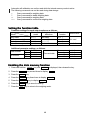
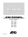
Analytical Balance
GH-120
GH-200
GH-300
GH-202
GH-252
WM+PD4000891
This manual and Marks
All safety messages are identified by the following, “WARNING” or “CAUTION”, of
ANSI Z535.4 (American National Standard Institute: Product Safety Signs and
Labels). The meanings are as follows:
WARNING
CAUTION
A potentially hazardous situation which, if not avoided,
could result in death or serious injury.
A potentially hazardous situation which, if not avoided,
may result in minor or moderate injury.
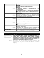
This is a hazard alert mark.
This mark is the IEC417 mark for "Caution. Hot surface".
Do not touch parts affixed with this mark without adequate protection.
This mark informs you about the operation of the product.
This manual is subject to change without notice at any time to improve the
product.
Product specifications are subject to change without any obligation on the part
of the manufacturer.
Under the copyright laws, the instruction manual and the software (program)
described in it are copyrighted, with all rights reserved.
The software may be installed into one computer and may not be installed into
other computers without the prior written consent of A&D Company. Copying
includes translation into another language, reproduction, conversion, photocopy
and offer or loan to another person.
The purchaser may make one copy of the software for backup purposes.
The manual and the software may not be copied, in whole or part, except as
described above.
Windows, Word and Excel are registered trademarks of the Microsoft
Corporation.
2004
All rights reserved.
Contents
Basic Operation
1.
Introduction .......................................................................................................................3
1.1.
About This Manual........................................................................................................3
1.2.
Features ........................................................................................................................3
1.3.
Compliance ...................................................................................................................4
2.
2.1.
Unpaking the Balance ......................................................................................................5
Installing The Balance ..................................................................................................6
3.1.
3.2.
3.3.
3.4.
Precautions .......................................................................................................................6
Before Use ....................................................................................................................6
During Use ....................................................................................................................7
After Use........................................................................................................................8
Power Supply................................................................................................................8
3.
4.
Display Symbols and Key Operation ..............................................................................9
5.
5.1.
5.2.
Weighing Units................................................................................................................10
Units.............................................................................................................................10
Changing the Units .....................................................................................................11
6.1.
6.2.
6.3.
6.4.
Weighing .........................................................................................................................12
Basic Operation (Gram Mode)...................................................................................12
Dual Range .................................................................................................................13
Counting Mode (PCS) ................................................................................................14
Percent Mode (%).......................................................................................................16
6.
Adapting To The Environment
7.
Response Adjustment ....................................................................................................17
7.1.
Automatic Response Adjustment ..............................................................................17
7.2.
Manual Response Adjustment...................................................................................18
8.
8.1.
8.2.
8.3.
8.4.
8.5.
8.6.
8.7.
Calibration .......................................................................................................................19
Calibration Group........................................................................................................19
Automatic Self Calibration..........................................................................................20
One-Touch Calibration................................................................................................20
Calibration Test Using The Internal Mass .................................................................21
Calibration Using An External Weight .......................................................................22
Calibration Test Using An External Weight ...............................................................23
Correcting The Internal Mass Value ..........................................................................24
Selecting Functions
9.
Function Switch And Initialization ..................................................................................25
9.1.
Permit Or Inhibit ..........................................................................................................25
9.2.
Initializing The Balance...............................................................................................26
10.
10.1.
10.2.
10.3.
10.4.
10.5.
10.6.
Function Table ...................................................................................................27
Details Of The Function Table....................................................................................28
Display Symbol And Keys ..........................................................................................30
Description Of The Class "Environment, Display"....................................................31
Description Of The Item "Data Output Mode"...........................................................32
Description Of The Item "Data Format".....................................................................33
Data Format Examples ..............................................................................................36
Instruction manual
1
GH series
10.7.
Clock And Calendar Function ....................................................................................38
11.
11.1.
11.2.
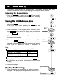
ID Number And GLP Report ..........................................................................................40
Setting The ID Number...............................................................................................40
GLP Report .................................................................................................................41
12.
12.1.
12.2.
12.3.
Data Memory ..................................................................................................................46
Notes on Using Data Memory ...................................................................................46
Data Memory for Weighing Data ...............................................................................47
Data Memory for Calibration and Calibration Test....................................................50
13.
Underhook ......................................................................................................................51
14.
Density Measurement ....................................................................................................52
Interface And Communication
15.
Standard Input & Output Interface.................................................................................55
15.1.
RS-232C Interface......................................................................................................55
15.2.
Connection to peripheral equipment .........................................................................56
15.3.
Commands..................................................................................................................58
Maintenance
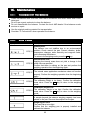
16.
Maintenance ...................................................................................................................62
16.1.
Treatment Of The Balance.........................................................................................62
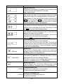
16.2.
Error Codes.................................................................................................................62
16.3.
Other Display ..............................................................................................................64
16.4.
Checking The Balance Performance And Environment ..........................................65
16.5.
Asking For Repair .......................................................................................................65
17.
17.1.
17.2.
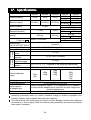
Specifications ..................................................................................................................66
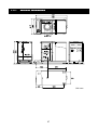
External Dimensions...................................................................................................67
Options and Peripheral Instruments..........................................................................68
18.
18.1.
18.2.
Terms/Index ....................................................................................................................70
Terms...........................................................................................................................70
Index............................................................................................................................71
2
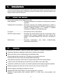
1.
Introduction
This manual describes how the balances of GH series work and how to get the most out of
them in terms of performance. Read this manual thoroughly before using the balance and
keep it at hand for future reference.
1.1.
About This Manual
This manual consists of the following five parts:
Basic operation ........................ Describes precautions, the balance's construction and basic
operation.
Adapting to the environment .... Describes response (and stability) adjustment to adapt to
the environment where there is vibration or drafts, the way to
maintain weighing precision in a variation of ambient
temperature, calibration and calibration test.
Functions ................................... Describes functions of the balance.
RS-232C serial interface ......... Describes the serial interface that can communicate with a
computer that requests weighing data and controls the
balance. This serial interface is for use with a computer or
printer.
Maintenance ............................ Describes maintenance, error codes, troubleshooting,
specifications and options.
1.2.
Features
Automatic self calibration, using the internal mass, adapting to changes in temperature.
Response adjustment adapting to drafts and/or vibration automatically.
Memory function to store weighing data and calibration data.
When weighing data is stored only, 200 data can be stored in maximum.
Interval memory mode to store the weighing data periodically.
Good laboratory practice (GLP) data can output using the RS-232C serial interface.
A built-in clock and calendar that can add the time and date to the output data.
Underhook, available as an option, for measuring density and weighing magnetic materials.
Multiple weighing units with most of the common units used around the world.
Density mode for calculating the density of a solid.
Standard RS-232C serial interface to communicate with a computer.
Windows communication tools software (WinCT) to allow easy communication with
Windows.
3
1.3.
1.3.1.
Compliance
Compliance
Compliance With FCC Rules
Please note that this equipment generates, uses and can radiate radio frequency
energy. This equipment has been tested and has been found to comply with the limits
of a Class A computing device pursuant to Subpart J of Part 15 of FCC rules. These
rules are designed to provide reasonable protection against interference when
equipment is operated in a commercial environment. If this unit is operated in a
residential area, it may cause some interference and under these circumstances the
user would be required to take, at his own expense, whatever measures are necessary
to eliminate the interference.
(FCC = Federal Communications Commission in the U.S.A.)
1.3.2.
Compliance With EMC Directives
This device features radio interference suppression in compliance with valid EC
Regulation 89/336/EEC.
Note: The device may be adversely affected under extreme electromagnetic influences.
4
2.
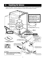
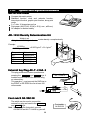
Unpaking the Balance
Unpack the balance carefully. Keep the packing material to be used for transporting the
balance in the future. See the illustrations to confirm that everything is contained.
Fine range breeze break ring
This ring is an accessory for
GH-252 and GH-202.
Before weighing of which the
mininum display is 0.01 mg,
install this ring in place of the
"breeze break ring" to avoid
errors caused by draft.
Weighing chember
Weighing pan
Pan support
Breeze break ring
Dust plate
Fine range breeze break ring
Floor plate
Keys
Leveling foot
Bubble sprit level
Display
Display cover
External Key Jack
Serial interface
(RS-232C,
D-sub 9 pins)
AC adapter jack
Windows communication
software (WinCT)
Position of placing
AC adapter labels
Terminal cover
AC adapter labels
AC adapter
Note Please confirm that the AC adapter
type is correct for your local voltage
and receptacle type.
Grounding
terminal
5
Leveling foot
2.1.
1
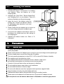
Installing The Balance
Install the balance as follows:
Consider the section "3. Precautions " for installing
your balance. Place the balance on a firm
weighing table.
2
Assemble the "Dust Plate", "Breeze Break Ring"
and "Weighing Pan" on your balance. There is a
reference illustration on the previous page.
3
Adjust the level of the balance using the
leveling feet. Ground the balance chassis
for discharging static electricity if you have
a static problem.
Leveling feet
4
Please confirm that the adapter type is correct for
your local voltage and power receptacle type.
5
Connect the AC adapter to the balance. Warm up
the balance for at least one hour with nothing on
the weighing pan.
6
Calibrate the balance before use. Refer to "8.
Calibration".
3.
Precautions
3.1.
Before Use
Use
Bubble sprit level
Connect the
AC adapter
To ensure that you get the most from your balance, please try to follow these conditions as
closely as possible.
Please confirm that the AC adapter type is correct for your local voltage and receptacle type.
Ensure a stable power source when using the AC adapter.
The best operating temperature is about 20°C / 68°F at about 50% Relative Humidity.
The weighing room should be free of dust.
The weighing table should be solid and free from vibration, drafts (such
as frequently opening doors or windows) and as level as possible.
Corners of rooms are best as they are less prone to vibrations.
Do not install the balance near heater or air conditioners.
Do not install the balance in direct sunlight.
Do not use the balance near other equipment which produces magnetic fields.
Keep the balance level by using the bubble spirit level.
Calibrate the balance before using and after moving it to another location.
Please warm-up the balance for at least one hour. Plug-in the AC adapter as usual.
Do not place or use the balance where there is flammable or corrosive gas present.
6
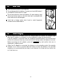
3.2.
During Use
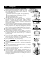
Note the following items to get accurate weighing data.
Metal case
Discharge static electricity from the weighing material.
Charged material
When weighing sample (plastics, insulator, etc.) could
have a static charge, the weighing value is influenced.
Ground the balance, and
Eliminate the static electricity by AD-1683 as an accessory.
Or try to keep the ambient humidity above 45%RH.
Or use the metal shield case.
Grounding
Or wipe plastic sample with the wet cloth.
This balance uses a strong magnet as part of the balance
assembly, so please use caution when weighing magnetic
materials. If there is a problem, use the underhook (on the
bottom of the balance) to suspend the material away from the
influence of the magnet.
Magnet material
Cancel the temperature difference between the weighed sample
and the environment. When a sample is warmer (cooler) than the
Draft
ambient temperature, the sample will lighter (heavier) than true
mass. This error is due to the rising (falling) draft next the sample.
20°C 40°C
Make each weighing gently and quickly to avoid errors due to
Weighing pan
changes in the environmental conditions.
Before weighing of which the minimum display is 0.01 mg for
GH-252 and GH-202, the "fine range breeze break ring" can
be installed in place of the "breeze break ring" to avoid errors
caused by draft.
Do not drop things upon the weighing pan, or put a weight
beyond the range of the balance on the weighing pan.
Do not use a sharp instrument (such as a pencil or ball point
pen) to press the keys, use your finger only.
Press the RE-ZERO
possible errors.
key before each weighing to prevent
Calibrate the balance periodically so as to eliminate possible
errors.
Take into consideration the affect of air buoyancy on a sample
when more accuracy is required.
Avoid that a foreign matter (dust, liquid or metal fragments)
invades into the inside balance.
Operate your balance gently. Shorten the operation time as
much as possible ( Opening and closing door, putting and
removing sample). Use a pair of tweezers (pincette) to avoid
temperature changes due to heat from inserting your hand into
the weighing chamber.
7
Fine range breeze
break ring
Shock
3.3.
After Use
Avoid mechanical shock to your balance.
Do not disassemble the balance. Contact your local A&D dealer if
your balance needs service or repair.
Do not use solvents to clean the balance. For best cleaning, wipe
with a dry lint free cloth or a lint free cloth that is moistened with
warm water and a mild detergent.
Avoid that a foreign matter (dust, liquid or metal fragments)
invades into the inside balance.
3.4.
Power Supply
Do not remove the AC adapter while the internal mass is in motion, for example, right
after the AC adapter is connected, or during calibration using the internal mass.
If the AC adapter is removed under the conditions described above, the internal mass
will be left unsecured, that may cause mechanical damage when the balance is moved.
Before removing the AC adapter, press the ON:OFF key and confirm that zero is
displayed in weighing mode.
When the AC adapter is connected, the balance is in the standby mode if the standby
indicator is on. This is a normal state and does not harm the balance. For accurate
weighing, we recommend that you plug in your balance for at least an hour before use
so it can warm up.
8
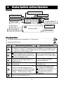
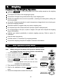
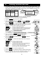
4.
Display Symbols and Key Operation
Display
The amount of stored data
with memory data function
Response indicator
Processing indicator
Units
Stabilization indicator
Standby indicator
of power supply
Standby indicator of
Interval memory function
Weighing data or
stored data
The current
data number
Prior notice indicator of
automatic self calibration
Blinking indicators
Interval memory,
active indicator
Key Operation
Press and release the key immediately" or "Click the key" .........................................
Press and hold the key ..................................................................................................
Key
When pressed and released
When pressed and held
The key to turn the display ON and OFF. The standby indicator is displayed when
the display is turned off. The weighing mode is enabled when the display is turned
on. This key is available anytime. Pressing the key during operation will interrupt
the operation and turn the display OFF.
In the weighing mode, the key to turn the
minimum weighing value ON and OFF.
The key to enter the function table
In the counting or percent mode, the key mode. Refer to "10. Function Table".
to enter the sampling mode.
The key to switch the preset weighing units
The key to perform automatic
stored in the function table. Refer to "5.
response adjustment.
Weighing Units".
The key to perform calibration using the
The key to display other items of the
internal mass.
calibration menu.
No function at the factory setting.
The key to store the weighing data in
By changing the function table:
memory or outputs to a printer or personal
"Title block" and "End block" for
computer depending on the function table
GLP report are outputted.
settings. (Factory setting = output)
The data memory menu is
displayed.
The key to set the display to zero.
9
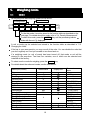
5.
Weighing Units
Units
5.1.
All weighing units and weighing modes are as follows:
Percent mode
Counting mode
g
mg
pcs
%
oz
ozt
ct
d
m
t
tl
GN
dwt
mom
Density mode
To use this mode, it must be stored in the function table as described on the
next page. For details about this mode, refer to "14. Density Measurement".
To select this mode, press the MODE key until the processing indictor
blinks with the unit "g" displayed.
A unit or mode can be selected and stored in the function table as described in "5.2.
Changing the Units".
If the law in your area permits, you may use all of the units. You can disable the units that
you don't regularly use. And you are able to turn them back on.
If a weighing mode (or unit of mass) has been turned off, that mode or unit will be
missing in the sequence. Tael has four varieties, one of which can be selected and
installed at the factory.
To select a unit or mode for weighing, press the MODE key.
For details about the units and modes, see the table below:
Name (unit, mode)
Gram
milli-gram
Counting mode
Percent mode
Ounce (Avoir)
Troy Ounce
Metric Carat
Momme
Pennyweight
Grain (UK)
Tael (HK general, Singapore)
Tael (HK jewelry)
Tael (Taiwan)
Tael (China)
Tola (India)
Messghal
Density mode
Abbreviation
g
mg
pcs
%
oz
ozt
ct
mom
dwt
GN
tl
t
m
d
10
Conversion
factor
1g
0.001 g
28.349523125 g
31.1034768 g
0.2 g
3.75 g
1.55517384 g
0.06479891 g
37.7994 g
37.429 g
37.5 g
31.25 g
11.6638038 g
4.6875 g
Refer to "14. Density Measurement"
Display unit
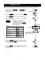
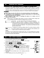
5.2.
Changing the Units
The units or modes can be selected and stored in the function table. The sequence of
displaying them can be arranged so as to fit the frequency of use in the function table.
1
2
Press and hold the RANGE key until ba5fnc of the
function table is displayed in the weighing mode, then
release the key.
Press and hold
Press the RANGE key several times to display Unit .
To unit
3
Press the PRINT key to enter the unit selection mode.
4
Specify a unit or mode in the order to be displayed
using the following keys.
RANGE key ....... To display the units sequentially.
RE-ZERO key .... To specify a unit or mode.
The stabilization indicator
appears when the displayed unit or
mode is specified.
Examples
Unit
Display
Gram
Examples
g
Milli-gram
mg
Counting mode
pcs
Percent mode
%
Densitymode
d
Displays the units
sequentially
5
Press the PRINT key to store the units or modes.
The balance displays end and then displays the next
menu item of the function table.
6
Press the CAL key to exit the function table. Then
the balance returns to the weighing mode with the
selected unit.
11
6.
Weighing
Weighing
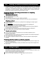
Cautions For The Weighing Operation
Press the RE-ZERO key to prevent possible error before putting sample on the weighing
pan each time.
Put sample to the center of the weighing pan gently.
Temperature changes during measurement may cause weighing error.
Shorten the operation time as much as possible. ( Opening and closing door, putting and
removing sample)
Use a pair of tweezers (pincette) to avoid a temperature change that is due to having your
hand in the weighing chamber.
Electrified material or magnetic body may cause a weighing error.
Do not press keys with a sharp instrument (such as a pencil or ball point pen).
Do not drop things on the pan, or place a weight on the pan that is beyond the weighing
range of the balance.
Calibrate your balance periodically to maintain weighing accuracy. Refer to section "8.
Calibration".
Keep the area clean and dry.
Consider section "3. Precautions" for weighing operation.
For precision weighing, keep the AC adapter connected to the balance.
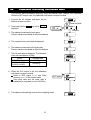
6.1.
Basic Operation (Gram Mode)
Read section "4. Display symbols and Key operation" before operation.
Note
When turning on the balance that is put the cantainer on the
pan, display becomes zero by tare function. automatically.
1
Turn on thebalance using the ON:OFF key.
2
Select a preset unit (of g or mg) using the MODE key.
3
Put the container on the weighing pan, if necessary.
Press the RE-ZERO key to cancel net weight. Then
zero is displayed.
Container : A vessel placed on the pan, but not to be
included in the weighing data.
4
Place sample on the pan or in the container.
5
Wait for the stabilization indicator
value.
6
Remove the sample and container from the pan.
Container
Weighing pan
Stabilization
indicator
Sample
and read the
Remove them
12
6.2.
Dual Range
Precision range
Standard range
Weighing range
GH-252
GH-202
0 g to 101 g
0 g to 51 g
101 g to 250 g
51 g to 220 g
GH-252 and GH-202 are equipped
with two ranges of "precision range"
and "standard range".
The range is switched automatically
depending on the value displayed.
Pressing the RE-ZERO key allows
weighing in the precision range,
regardless of the tare value.
Pressing the RANGE key, the
range can be switched these
ranges alternately.
Available minimum display
0.01 mg
Precision Range
Turn on the balance
0.1 mg
0.1 mg
1 mg
1 mg
Standard Range
Turn on the balance
Minimum display
Minimum display
0.1mg
0.1mg
Minimum display
Minimum display
0.01mg
1mg
Minimum display
1mg
When putting and weighing the sample
with precision range of minimum display
0.01 mg, minimum display is changed to
0.1 mg of standard range. When removing
the sample, minimum display is changed to
0.01 mg of precision range automatically.
Minimum display
0.01mg
Minimum display
0.1mg
Minimum display
0.01mg
When a tare weight (container mass value)
exceeds precision range, even if net weight
is within precision range, 0.01 mg of
precision range can not be selected for
minimum display. In order to select 0.01
mg of precision range, remove tare weight
and press the RE-ZERO key to cancel it.
Minimum display
0.01mg
Minimum display
0.1mg
Zero display after putting
container
Minimum display 0.1mg
When a minimum display 0.1mg or 1mg is
selected by the RANGE key, even if
changing range, minimum display is
maintained.
13
Zero display after remove
and cancel container.
Minimum display 0.01mg
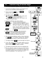
6.3.
Counting Mode (PCS)
This is the mode to determine the number of objects in a sample based on the standard
sample unit mass. The unit mass means an average mass of the samples. The smaller the
variation in the samples, the more accurate the count will be. The balance is equipped with the
Automatic Counting Accuracy Improvement (ACAI) function to improve the counting accuracy.
Note
If the sample unit mass variable, the difference from sample
to sample, is too large, it may cause a counting error.
Selecting The Counting Mode
1
Press the MODE key to select the unit pcs (counting mode).
Storing A Sample U
Unit
nit Mass (Weighing Input Mode)
2
Press the RANGE key to enter the sample unit mass storing mode.
3
To select the number of samples using the RANGE key.
It may be set to 10, 25, 50 or 100.
Advise A greater number of samples will yield more
accurate counting result.
4
Place a container on the weighing pan, if necessary.
Press the RE-ZERO key to cancel the weight (tare).
The number specified in step 3 appears.
Example: 25 0 pcs is displayed if 25 is selected in step 3.
5
Place the number of samples specified on the pan.
In this example, 25 pieces.
6
Wait for the stabilization indicator to come on.
Press the PRINT key to calculate and store the unit
mass. Then the balance displays 25 pcs and is set to
count samples with this unit mass. (The sample unit
mass stored, even if the AC adapter is removed, is
maintained in non-volatile memory.) To improve the
accuracy of the unit mass, proceed to step 8.
Notes
If the balance judges that the mass of the samples is too
light (under 0.0001g) and can not be stored as the unit mass,
it displays lo .
If the balance judges that the mass of the samples is too
light to acquire accurate weighing, it displays an error
requiring the addition of more samples to the specified
number.
Example: 150 - pcs appears, requiring 25 more samples.
Add 25 samples and press the PRINT key. When the
unit mass is stored correctly, the balance proceedes to
the counting mode.
Weighing pan
Container
25 Samples
Place samples
Counting Operation
7
Place the samples to be counted on the pan.
14
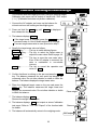
Counting result
Counting Mode Using The ACAI Function
The ACAI is a function that improves the accuracy of the unit mass automatically by
increasing the number of samples as the counting process.
ACAI: Automatic Counting Accuracy Improvement
8
If a few more samples are added, the
processing indicator turns on. To prevent an
error, add three or more. The processing
indicator does not turn on if overloaded. Try to
add the same number of samples as
displayed.
9 The balance re-calculates the unit mass while
the processing indicator is blinking. Do not
touch the balance or samples on the pan until
the processing indicator turns off.
10 Counting accuracy is improved when the
processing indicator turns off.
Each time the above operation is performed,
a more accurate unit mass will be obtained.
There is no definite upper limit of ACAI range
for the number of samples exceeding 100.
Try to add the same number of samples as
displayed.
11 Remove all the samples used in ACAI and
proceed with the counting operation using the
improved unit mass.
From step 7
Add a few
more samples.
The mark turns on
at proper range.
The mark turns on and
off during calculation.
The mark turns off after
the unit mass is improved.
Renew
Note ACAI will not function on the unit mass entered using the keys, or digital input
mode.
15
6.4.
Percent Mode (%)
The percent mode displays the weighing value in percentage compared to a 100%
reference mass and is used for target weighing or checking the sample variance.
Selecting The Percent Mode
1 Press the MODE key to select the unit % (Percent mode).
If the percent mode can not be selected, refer to "5. Weighing
Units".
Storing The 100% Reference
eference Mass
2
3
4
Press the RANGE key to enter the 100% reference mass
storing mode.
Even in the storing mode, pressing the MODE key will
switch to the next mode.
Place a container on the weighing pan, if necessary. Press
the RE-ZERO key to cancel the weight (tare). The balance
displays 100 0 %.
Pan
Container
Place the sample to be set as the 100% reference mass on
the pan or in the container.
5
Press the PRINT key to store the reference mass. The
balance displays 100.00 %. (The decimal point position
depends on the reference value. The reference mass stored,
even if the AC adapter is removed, is maintained in
non-volatile memory.)
Note
Position of decimal point can be changed by 100% mass.
100% mass
Minimum display
0.0100g to 0.0999g
1%
0.1000g to 0.9999g
0.1%
1.0000g to weighing capacity
0.01%
100% mass
If the balance judges that the mass of the sample is too light
(under 0.01g) to be used as a reference, it displays lo .
A 100%mass can be stored in the balance without power
supply.
6
Remove the sample.
Place sample
Reading The Percentage
7
Place a sample to be compared to the reference mass on
sthe pan. The displayed percentage is based on the 100%
reference mass.
Percentage
16
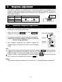
7.
Response Adjustment
This function stabilizes the weighing value, reducing the influence on weighing that is
caused by drafts and/or vibration at the place where the balance is installed. This function
adjusts by automatically analyzing the environment or by hand-operation. The function has
three stages as follows :
Response
Indicator Parameter Response
Stability
indicator
FAST
Cond 0
Fast response, Sensitive value
MID.
Cond 1
Slow response, Stable value
SLOW
Cond 2
7.1.
Automatic Response Adjustment
This function automatically updates the response adjustment by analyzing the influence of
the environment using the internal mass.
1
Press and hold the MODE key until RESPONSE is
displayed, and then release the key.
2
The balance automatically sets the response characteristic.
Caution Do not allow vibration or drafts to affect the
balance during adjustment.
3
After automatic adjustment, the balance displays the
updated response indicator and returns to the weighing
mode.
Press and hold
Release
Result
Note
If the automatic response adjustment fails, the balance displays CH ng . Check the ambient
conditions such as breeze and vibration, also check the weighing pan. Then, perform the
adjustment again. To return to the weighing mode, press the CAL key.
If there is matter on the weighing pan, the balance displays CH 0 . Remove them from the
pan. To return to the weighing mode, press the CAL key.
Advise
If the automatic response adjustment is not helpful, try "7.2. Manual Response Adjustment".
17
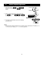
7.2.
1
Manual Response Adjustment
Press and hold the MODE key until RESPONSE is
displayed. And then, press the MODE key again
quickly.
Press and hold
Release
2
Select a stage of the response adjustment using
the MODE key. Either FAST , MID. or SLOW
can be selected.
Select a parameter
with pressing it.
Release and wait
3
The balance automatically returns to the weighing
mode after a few
Advise
If the automatic response adjustment is not helpful, specify a parameter of "Condition (Cond)
" of "Environment, Display (ba5fnc)" in with key operation.
18
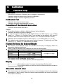
8.
Calibration
8.1.
Calibration Group
Calibration
Automatic self calibration (Calibration due to changes in temperature)
Calibration using the internal mass (One-touch calibration)
Calibration using an external weight that you have
Calibration Te
Test
st
Calibration test using the internal mass
Calibration test using target mass that you have
Correction of the internal mass value
Correction of the internal mass value
Caution
Do not allow vibration or drafts to affect the balance during calibration.
Calibration test does not perform calibration.
To output the data for GLP using the RS-232C interface, set "GLP output (info)" of "Data
output (dout)". Refer to "10. Function Table". Time and date can be added to GLP report. If
the time or date is not correct, adjust them. Refer to "10.7 Clock and Calendar Function".
Calibration test is available only when "GLP output (info)" of "Data output (dout)" is set .
The calibration and calibration test data can be stored in memory. To store them, set "Data
memory (data)". Refer to "12. Data Memory" for details.
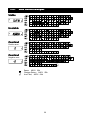
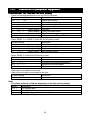
Caution On Using An External Weight
The accuracy of an external weight can influence the accuracy of weighing. Select an
appropriate weight as listed below:
Select a mass for calibration and calibration test from the following table.
Model
Usable calibration mass
Adjustable range
GH-120
50g,
100g*
-15.0mg to +15.9mg
GH-200
100g, 200g*
GH-300
100g, 200g*, 300g
GH-202, GH-252 20g,
50g,
100g, 200g*
-15.00mg to +15.99mg
The calibration mass in bold type: factory setting
The calibration mass value can be adjusted within the range above.
Display
This indicator means "In process of measuring calibration data".
Do not allow vibration or drafts to affect the balance while the indicator is
displayed.
About the internal mass
The internal mass may change due to corrosion or other damage caused by the operating
environment, or due to aging. Check the internal mass periodically and correct the internal
mass value if necessary.
19
8.2.
Automatic Self Calibration
Automatic self calibration due to changes in temperature
This function automatically calibrates the balance when the balance detects an ambient
temperature change. If GLP output is selected in the function table, the balance outputs the
calibration report or stores the data in memory. Automatic self calibration functions even if
the display is turned off (standby state). Refer to "9-1. Permit Or Inhibit" for the operation.
Caution
When using automatic self calibration, do not put something on the weighing pan.
If something is on the weighing pan, the balance decides that it is in use and does
not perform automatic self calibration.
When weighing a light sample or installing the balance in a system, turn off
automatic self calibration.
Note
When turning on the balance with nothing on the pan, if putting heavier sample than
0.5 g, the balance detects the state that a sample is put on the pan.
The mark
is " prior notice indicator of automatic self calibration".
When the balance detects a change in ambient temperature, this
indicator blinks and automatic self calibration is required. If the balance is
not used for several minutes with this indicator blinking, the balance
preforms automatic self calibration. The environment will affect the time
that the indicator blinks.
The balance is measuring calibration data. Do not allow vibration or drafts
to affect the balance while this indicator is displayed. After calibration, the
balance returns to indicate the previous display.
Advise
The balance can be used while the indicator blinks. But, it is recommended that to maintain
the accuracy, stop using the balance and confirm that there is nothing on the pan and allow
the balance to perform self calibration.
8.3.
1
2
3
4
5
6
OneOne-Touch Calibration
This function calibrates the balance using the internal mass.
The only operation required is to press the CAL key.
Connect the AC adapter and warm up the balance for at least
one hour with nothing on the weighing pan.
Press the CAL key to display Cal in .
The balance performs calibration using the internal mass.
Do not allow vibration or drafts to affect the balance.
The balance displays end after calibration. If the GLP output is
set, the balance displays glp and outputs the calibration
report using the RS-232C interface or stores the data in memory.
Refer to "GLP output (info)" and "Data memory (data)" of the
function table.
The balance will automatically return to the weighing mode after
calibration.
Confirm weighing accuracy using calibration test (CC in).
20
GLP output
8.4.
Calibration Test Using The Internal
Internal Mass
This function tests the balance accuracy using the internal mass. (Balance isn ot calibrated)
When the GLP output is set, the calibration test report is output or stored.
1
Connect the AC adapter and warm up the
balance at least one hour.
Press and hold
2
Press and hold the CAL key until is CC in
displayed.
Release
3
The balance measures the zero point.
Prevent vibration and drafts to affect the balance.
4
The measured zero point data is displayed.
5
The balance measures the full scale data.
Prevent vibration and drafts to affect the balance.
7
The full scale data is displayed. The tolerance
of the full scale data is ±0.2mg.
Model
Full scale data
GH-120
100.000 g
GH-200, GH-300,
200.000 g
GH-202, GH-252
8
When the GLP output is set, the calibration
test report is output or stored.
Refer to "GLP output (info)" and "Data
memory (data)" of the function table.
Zero point data and full scale data is
displayed (or outputted) in unit of 0.0001g.
8
GLP output
The balance automatically returns to the weighing mode.
21
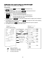
8.5.
Calibration Using An External Weight
This function calibrates the balance using an external weight.
1
Connect the AC adapter and warm up the balance for at
least one hour with nothing on the weighing pan.
2
Press and hold the CAL key until Calout is
displayed, then release the key.
3
4
5
Press
and
hold
Release
The balance displays Cal 0 .
If you want to change the calibration mass, press
the RANGE key and proceed to step 4.
If you use the calibration mass value stored in the
balance, proceed to step 5.
Select
Specify the calibration mass value as follows:
RANGE key ........ The key to switch blinking figures.
RE-ZERO (+)key.... The key to select the calibration mass or
MODE (-)key
adjust the mass value. Refer to page 19.
..........
PRINT key
The key to store the new mass value.
Even if the AC adapter is removed, the
data is maintained in non-volatile memory.
..............
CAL key
The key to cancel the operation and return
to Cal 0 .
Specify
Confirm that there is nothing on the pan and press the
PRINT key. The balance measures the zero point.
Do not allow vibration or drafts to affect the balance.
The balance displays the calibration mass value.
Example:
New weight
100.0012 g
6
Place the displayed calibration weight on the pan and press
the PRINT key. The balance measures the calibration
mass. Do not allow vibration or drafts to affect the balance.
7
The balance displays end . Remove the weight from the pan.
8
If the "GLP output (info)" the function table is set, the
balance displays glp and outputs or stores "Calibration
Report". Refer to "11.2. GLP Report" for details.
9
The balance will automatically return to the weighing mode.
Place weight
10 Place the calibration weight on the pan and confirm that the
value displayed is correct. If it is not within the range, check
the ambient conditions such as breeze and vibration also
check the weighing pan. Then, repeat steps 1 to 10.
Remove
GLP output
22
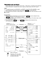
8.6.
Calibration Test Using An External Weight
This function tests the weighing accuracy using an external weight.
Calibration test report can be output or stored with "GLP output
(info)" (Calibration test does not perform calibration).
1
Connect the AC adapter and warm up the balance for
at least one hour with nothing on the weighing pan.
2
Press and hold the CAL key until CC out is displayed,
then release the key.
3
The balance displays CC 0 .
If the target mass is changed, press the RANGE key and
proceed to step 4. A list of usable weights is on 19 page.
If current target mass value is used, proceed to step 5.
4
Specify the target mass value as follows:
RANGE key ............The key to switch blinking figures.
RE-ZERO (+)key .......The key to select the target mass or
MODE (-)key
adjust the mass value. Refer to page 19.
PRINT key ..............The key to store the new mass value.
Even if the AC adapter is removed, the
data is maintained in non-volatile
memory.
CAL key..................The key to cancel the operation and
return to CC 0 .
5
Confirm that there is nothing on the pan and press the PRINT
key. The balance measures the zero point and displays the
measured value. Do not allow vibration or drafts to affect the
balance. The balance displays the target mass value.
6
Place the displayed target mass on the pan and press the
PRINT key. The balance measures the target mass and
displays the measured value. Do not allow vibration or drafts
to affect the balance.
7
The balance displays end .
Remove the weight from the pan.
8
The balance displays glp and outputs or stores "calibration
test report. Refer to "11.2. GLP Report" of the function table
for details.
9
Press
and
hold
Release
Select
Specify
Example:
New weight
100.0012 g
Place weight
Remove
The balance will automatically return to the weighing mode.
GLP output
23
8.7.
Correcting The Internal Mass Value
The balance can correct the internal mass value within the range shown below. This
function corrects the internal mass value to conform to an external weight. The corrected
mass value is maintained in non-volatile memory even if the AC adapter is removed. The
internal mass value is corrected as follows:
The same mass
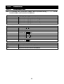
Model
Target
Range
200g
200g
Correct the internal
GH-120
100.000 g
mass by +0.6mg.
GH-200
Calibrate
with this
200.
0
000
g
200.0006g
±1.5 mg
GH-300
200.000 g
internal
mass.
GH-202
Corrected external weight
GH-252
1
Calibrate the balance using the internal mass. (one-touch calibration)
Example: 200.0000 g is corrected to +0.6 mg (200.0006 g).
2
Press the ON:OFF key to turn off the display.
3
While pressing and holding the PRINT key and the RANGE key,
press the ON:OFF key. The balance displays p5 .
4
Press the PRINT key. Then the balance displays the function
switches. Set the function table switch and internal mass correction
switch to "1" as shown above using the following keys.
RANGE key ........ The key to select blinking figure.
RE-ZERO key ..... The key to change the value of the blinking figure..
PRINT key .......... The key to store it and return to weighing mode.
CAL key ............. The key to cancel current operation.
Function table switch
Correction switch of internal mass
5
Weighing mode
Press and hold the RANGE key to enter the function
table and release the key when ba5fnc is displayed.
6
Press the RANGE key several times until C5 in is displayed,
then release the key.
7
Press PRINT key. Correct the internal mass value using the
following keys.
RE-ZERO (+)key... The key to select the value.
MODE (-)key ........ The key to select the value.
PRINT key .......... The key to store the new value and display the
next menu item of the function table.
.............
CAL key
The key to cancel this correction and display
the next menu item of the function table.
8
Press the CAL key to return the weighing mode.
9
Press the CAL key to calibrate the balance using the internal mass.
10 Check the correction that has been performed properly with the
external weight. If the value is incorrect, repeat the correction.
24
Press and hold
Press and hold
Press
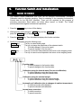
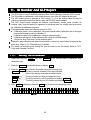
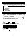
9.
9.1.
Function Switch And Initialization
Permit Or Inhibit
The balance stores parameters that must not be changed unintentionally (Example:
Calibration data for accurate weighing, Data for adapting to the operating environment,
Control data for the RS-232C interface). There are five switches for the purpose of
protecting parameters. Each switch can select either "permit" or "inhibit". The "inhibit"
protects parameters against unintentional operations.
1
Press the ON:OFF key to turn off the display.
2
While pressing and holding the PRINT key and the RANGE key,
press the ON:OFF key to display p5 .
3
Press the PRINT key. Then the balance displays the function switches.
4
Specify the switches using the following keys.
RANGE key ............The key to select blinking digit.
RE-ZERO key .........The key to change the parameter of the selected switch.
0 To inhibit changes. (Can not be used.)
1 To permit changes. (Can be used.)
..............
PRINT key
The key to store the new parameter and return to the weighing mode.
.................
CAL key
The key to cancel current operation and return to the weighing mode.
Function table
0 To inhibit changes to the function table.
1 To permit changes to the function table.
Calibration using the internal mass (One-touch calibration)
0 To inhibit calibration using the internal mass.
1 To permit calibration using the internal mass.
Calibration using the external weight
0 To inhibit calibration using the external weight.
1 To permit calibration using the external weight.
Automatic self calibration (due to changes of ambient temperature)
0 To inhibit automatic self calibration.
1 To permit automatic self calibration.
Internal mass correction
0 To inhibit correction.
1 To permit correction.
25
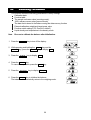
9.2.
Initializing The Balance
This function returns the following parameters to factory settings.
Calibration data
Function table
The sample unit mass value (counting mode),
100% reference mass value (percent mode)
The data that is stored in the balance using the data memory function
External calibration weight and target mass value
Function switch settings ("25. Permit Or Inhibit")
Liquid density and temperature in the density mode
Note
Be sure to calibrate the balance after initialization.
1
Press the ON:OFF key to turn off the display.
2
While pressing and holding the PRINT key and the
RANGE key, press the ON:OFF key to display
p5 .
3
Press the RANGE key to display Clr .
4
Press the PRINT key.
To cancel this operation, press the CAL key.
5
Press the RE-ZERO key to display Clr go .
6
Press the PRINT key to initialize the balance.
The balance will automatically return to the weighing mode.
26
Press and hold
Press
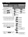
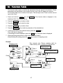
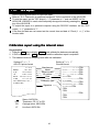
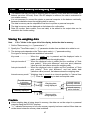
10. Function Table
This function table reads or rewrites the parameters that are stored in the balance. These
parameters are maintained in non-volatile memory, even if the AC adapter is removed.
This function table menu consists of two layers. The first layer is the "Class" and the second
layer is the "Item".
1
Press and hold the RANGE key until ba5fnc of the function table is displayed in the
weighing mode, then release the key
2
Press the RANGE key to select a class.
3
Press the PRINT key to enter the class
4
Press the RANGE key to select a item.
5
Press the RE-ZERO key to select a parameter of the selected item.
6
If storing parameters of the selected class, press the PRINT key.
Then next class is displayed.
If canceling the current operation, press the CAL key. Then next class is displayed.
7
When specifying parameters for other class, proceed to step 2.
When finishing the setting, press the CAL key to return to weighing mode.
Example
This example sets "Stores weighing data" for
"Data memory" and "1 minute" for "Interval time".
Item
"Data memory"
Step 4
Parameter
"Stores weighing data"
Press several
Step 5
times
Weighing mode
Start
Step 1
Press and
hold
Class
Step 2
Press several
times
Step 3
Step 6
Item
Step 8
Step 4
Item
"Interval time"
Finish
Weighing mode
27
Parameter
"1 minute"
Step 5
Step 7
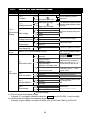
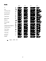
10.1.
Class
Details Of The Function Table
Item and Parameter
Cond
Condition
5t-b
Stability band width
ba5fnc
trc
Environment
Zero tracking
Display
5pd
Display refresh rate
pnt
Decimal point
p-on
Auto display-ON
Cl adj
Clock
Description
0
1
2
0
1
2
0
1
2
3
0
1
0
1
0
1
Fast response, sensitive value FAST
Slow response, stable value
Stable range is ±1 digit
Can be changed by response
MID. adjustment.
SLOW
The stabilization indicator illuminates
#1 when the display fluctuation is within
Stable range is ±3 digits
OFF
Normal
Middle
Strong
5 times/second
10 times/second
Point (.)
Comma (,)
OFF
ON
Refer to "10.7. Clock and Calendar Function"
0 Key mode
prt
Data output mode
1
2
3
dout
Data output
Auto print mode A
(Reference = zero)
Auto print mode B
(Reference = last stable value)
Stream mode /
Interval memory mode
Plus only
Minus only
Both
10 digits
100 digits
1000 digits
Not used
Stores weighing data
Stores calibration data
the range.
Keeps zero display by tracking zero
drift.
Period to refresh the display
Decimal point format
Turns on the weighing mode display
when the AC adapter is connected.
Confirms and sets the time and
date. The time and date are added
to the output data.
Accepts the PRINT key only when
the display is stable.
Outputs data when the display is
stable and conditions of ap-p, ap-b
and the reference value are met.
With data 0, outputs data
continuously; with data 2, uses
interval memory.
Displayed value>Reference
0
Displayed value<Reference
1
Regardless of displayed value
2
0
Difference between reference value
ap-b
and displayed value
1
Auto print difference
#2
2
0
data
Related items:
1
prt, int, d-no, 5-td, info
Data memory
2
: Factory settings.
#1 The unit of minimum display is digit.
Example: If 1 mg display is selected using the RANGE key for GH-300, 1 mg is one digit.
#2 Usable minimum display of the balance is one digit.
Example: In gram display, one digit is 0.00001 g for GH-252 and 0.0001 g for GH-300.
ap-p
Auto print polarity
28
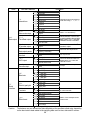
Class
Item and Parameter
Description
0 Every measurement
1 2 seconds
2 5 seconds
3 10 seconds
int
Interval time in the interval memory
4 30 seconds
mode when using prt 3, data 1
Interval time
5 1 minute
6 2 minute
7 5 minute
8 10 minute
d-no
0 No output
Refer to "12. Data Memory"
Data number output
1 Output
0 No output
Selects whether or not the time
dout
5-td
1 Time only
or date is added to the weighing
data. Refer to "10.7. Clock and
Date
only
Data output Time/Date output
2
Calendar Function" for details.
3 Time and date
5-id
0 No output
Selects whether or not the ID
number is output.
ID number output
1 Output
pU5e
0 No pause
Selects the data output interval.
Data output pause
1 Pause (1.6 seconds)
at-f
0 Not used
Selects whether or not automatic
feed is performed.
Auto feed
1 Used
Selects GLP output method.
0 No output
info
For how to set time and date to be
1 AD-8121 format
added, refer to "10.7. Clock and
GLP output
Calendar Function".
2 General data format
ar-d
0 Not used
Adjusts zero automatically after data
is output
Zero after output
1 Used
0
600 bps
1
1200 bps
bp5
2
2400 bps
Baud rate
3
4800 bps
4
9600 bps
5
19200 bps
0 7 bits, even
btpr
1 7 bits, odd
5if
Data bit, parity bit
Serial
2 8 bits, none
interface
Crlf
0 CR LF
CR: ASCII code 0Dh
LF: ASCII code 0Ah
Terminator
1 CR
0 A&D standard format
1 DP format
type
2 KF format
Refer to "10.5. Description of Item
"Data Format".
Data format
3 MT format
4 NU format
5 CSV format
: Factory settings.
Caution The balance may not transmit the data completely at the specified refresh rate, depending
on the baud rate or data added to the weighing data such as time, date and ID number.
29
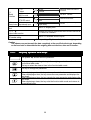
t-Up
Timeout
5if
erCd
Serial
AK, Error code
interface
Ct5
CTS, RTS control
d5 fnc
ldin
Density function Liquid density input
Unit
Unit
C5 in
Internal mass correction
id
ID number setting
0
1
0
1
0
1
0
1
No limit
1 second
No output
Output
Not used
Used
Water temperature
Liquid density
Selects the wait time to receive a
command.
AK: ASCII code 06h
Controls CTS and RTS.
Available only when density mode is
selected
Refer to "5. Weighing Units".
Displayed only when the internal mass value correction switch is set
to 1. Refer to "8. Calibration".
Refer to "11. ID Number And GLP Report".
: Factory settings. Digit is a unit of minimum weighing value.
Caution
The balance may not transmit the data completely at the specified refresh rate, depending
on the baud rate or data added to the weighing data such as time, date and ID number.
10.2.
Display Symbol And Keys
The symbol "〇
〇" shows effective parameter.
When pressing and holding the key in the weighing mode, the mode enters
the function table mode.
The key to select the class or item in the function table mode.
The key to change the parameter.
When displaying a class, the key enters an item in the class.
When displaying an item, the key stores the new parameter and displays the
next class.
When displaying an item, the key cancels the new parameter and displays the
next class.
When displaying a class, the key exits the function table mode and returns to
the weighing mode.
30
10.3.
Description Of The Class "Environment, Display"
Condition ( Cond )
Cond 0
This parameter is for sensitive response to the fluctuation of a mass value. Used
for powder target mass, weighing a very light sample or when quick response
weighing is required. After setting, the balance displays FAST.
Cond 2
This parameter is for stable weighing with slow response. Used to prevent a mass
value from drifting due to vibration or drafts. After setting, the balance displays
SLOW .
Notes
In automatic response adjustment, this parameter is selected automatically.
Stability band width ( 5t5t-b )
This item controls the width to regard a mass value as a stable value. When the fluctuation
per second is less than the parameter, the balance displays the stabilization indicator and
outputs or stores the data. The parameter influences the "Auto print mode"
5t-b 0 This parameter is used for sensitive response of the stabilization indicator. Used
for exact weighing.
5t-b 2
This parameter ignores slight fluctuation of a mass value. Used to prevent a mass
value from drifting due to vibration or drafts.
Zero tracking ( trc )
This function tracks zero point drift caused by changes in the environment and stabilizes the
zero point. When the weighing data is only a few digits, turn the function off for accurate
weighing.
trc 0
The tracking function is not used. Used for weighing a very light sample.
trc 1
The normal tracking function is used.
trc 2
The middle tracking function is used.
trc 3
The strong tracking function is used. Used for stable zero display.
Display refresh rate ( 5pd )
Period to refresh the display. This parameter influences "Baud rate", "Data output pause"
and "Stream mode".
Decimal point ( pnt )
The decimal point format can be selected.
Auto displaydisplay-ON ( p-on )
When the AC adapter is plugged in, the display is automatically turned on without the
ON:OFF key operation, to display the weighing mode. Used when the balance is built into
an automated system. one hour warm up is necessary for accurate weighing.
31
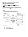
10.4.
Description Of The Item "Data Output Mode"
The parameter setting of "Data output mode (prt)" applies to the performance when the
"Data memory (data)" parameter is set to "2" (to store the weighing data) and when the data
is transmitted using the RS-232C interface.
Key mode
When the PRINT key is pressed with the stabilization indictor turned on, the balance
outputs or stores the weighing data and the display blinks one time.
Required setting
dout
prt 0
Key mode
Auto print modes A and B
When the displayed value is stable and the conditions of "Auto print polarity", "Auto print
difference" and reference value are met, the balance outputs or stores the weighing data.
When the PRINT key is pressed with the stabilization indictor turned on, the balance
outputs or stores the data and the display blinks one time.
Auto print modes A
Example
Required setting
For weighing each time a sample is placed and removed, with "ar-d"
set to "1" (to adjust zero after the data is output).
dout
prt 1
Auto print mode A (reference = zero)
dout
ap-p
Auto print polarity
dout
ap-b
Auto print difference
dout
ar-d 1 Zero after output
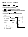
Auto print modes B
Example
Required setting
For weighing while a sample is added.
dout
prt 2
Auto print mode B (reference = last stable value)
dout
ap-p
Auto print polarity
dout
ap-b
Auto print difference
Stream mode
The balance outputs the weighing data continuously regardless of the display condition. The
display does not blink in this mode. The interval memory mode is used when the "Data
memory (data)" parameter is set to "1" (to store the weighing data).
Example
For monitoring data on a computer.
Required setting
dout
prt 3
Stream mode
dout
data 0 Data memory function is not used
ba5fnc 5pd
Display refresh rate
5if
bp5
Baud rate
Caution The balance may not transmit the data completely at the specified refresh rate,
depending on the baud rate or data added to the weighing data such as time,
date and ID number.
32
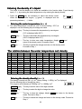
Interval
Interval memory mode
The weighing data is periodically stored in memory.
Example
For periodical weighing without a personal computer command and
to output all of the data, to a computer, at one time.
The GH series can use time and date with "Time/Date output (5-td)".
Required setting
dout
prt 3
Interval memory mode
dout
data 2
Data memory function is used
dout
int
Interval time
Optional setting
dout
5-td1, 2, or 3
Adds the time and date.
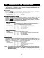
10.5.
Description Of The Item "Data Format"
A&D standard format
5if type
type 0
This format is used when the peripheral equipment can receive the A&D format.
If an AD-8121B is used, set the printer to MODE 1 or 2.
This format consists of fifteen or sixteen characters excluding the terminator.
When numerical characters without decimal point are exceeded eight characters for GH-252,
the format becomes sixteen characters.
A header of two characters indicates the balance condition.
The polarity sign is placed before the data with the leading zeros. If the data is zero, the plus
sign is applied.
The unit, consisting of three characters, follows the data.
Header
Data
Stable header
Unstable header
Overload header
Header
Data
Unit
Terminator
Stable header of counting mode
Unit
DP (Dump print) format
Terminator
5if type 1
This format is used when the peripheral equipment can not receive the A&D format.
If an AD-8121B is used, set the printer to MODE 3.
This format consists of sixteen characters excluding the terminator.
A header of two characters indicates the balance condition. No overload header is used.
The polarity sign is placed before the data, with spaces in place of leading zeros, if the data
is not zero or overloaded.
The unit, consisting of three characters, follows the data.
Header
Data
Stable header
Unstable header
Unit
Terminator
Stable header of counting mode
33
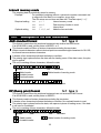
KF format
5if type 2
This is the Karl-Fischer moisture meter format and is used when the peripheral equipment
can only communicate using this format.
This format consists of fifteen characters excluding the terminator.
This format has no header characters.
The polarity sign is placed before the data, with spaces in place of leading zeros, if the data
is not zero or overloaded.
This format outputs the unit only for a stable value.
Data
Unit
Terminator
Stable value
Unstable value
MT format
5if type 3
A header of two characters indicates the balance condition.
The polarity sign is used only for negative data.
The weighing data uses spaces in place of the leading zeros.
The character length of this format changes dependent upon the unit
Header
Data
Unit
Terminator
Stable header
Unstable header
Overload header
NU (numerical) format
5if type 4
This format outputs only numerical data.
This format consists of ten characters excluding the terminator.
The polarity sign is placed before the data with the leading zeros. If the data is zero, the plus
sign is used.
Data
Terminator
34
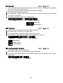
CSV format
5if type 5
This format separates the data of A&D standard format and the unit by a comma ( , ).
This format outputs the unit even when the data is overloaded.
When a comma ( , ) is selected for decimal point, separators are set to semicolon ( ; ).
When the ID number, data number, time and date are added at "Data output (dout)" of the
function table, outputs ID number, data number, date, time and weighing data in this order
and separates each item by a comma and treats all the items as one group of data.
ID number Data number
Date
Time
Weighing data
ID number
dout 55-id 1
Data number
dout
dout dd-no 1
The number to identify a specific balance.
This format consists of seven characters excluding the terminator.
This format outputs the data number just before the data is transmitted using the RS-232C
interface.
This format consists of six characters excluding the terminator.
When CSV format (5if type 5) is selected, the period ( . ) is replaced with a comma ( , ).
Data number
Terminator
Date
dout 55-td 2 or 3
Time
dout 55-td 1 or 3
The date output order can be changed in " Time/Date output (5-td)" and "Clock (Cl adj)".
The year is output in a four-digit format.
This format outputs time in 24-hour format.
35
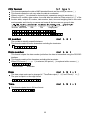
10.6.
Data Format Examples
Stable
Unstable
Overload
Positive error
Overload
Negative error
Space, ASCII 20h
Carriage Return, ASCII 0Dh
Line Feed, ASCII 0Ah
36
Units
A&D
D.P.
g
mg
Counting mode
Precent mode
Ounce (Avoir)
Troy Ounce
Metric Carat
Momme
Pennyweight
Grain
Tael (HK general, Singapore)
Tael (HK, jewelry)
Tael (Taiwan)
Tael (China)
Tola (India)
Messghal
Density
Space, ASCII 20h
37
KF
MT
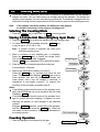
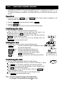
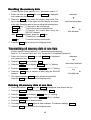
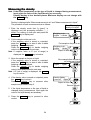
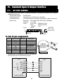
10.7.
Clock And Calendar Function
The balance is equipped with a clock and calendar function. When the "GLP output (info)"
parameter is set to "1" or "2" and the "Time/Date output (5-td)" parameter is set to "1", "2" or
"3", the time and date are added to the output data. Set or confirm the time and date as
follows:
Operation
1
Press and hold the RANGE key until ba5fnc of the function table is displayed in the
weighing mode, then release the key.
2
Press the RANGE key several times to display Cl adj .
3
Press the PRINT key.
The balance enters the mode to confirm or set the time and date.
Confirming the time
4
The current time is displayed with all the digits blinking.
When the time is correct and the date does not need to be
confirmed, press the CAL key and proceed to step 8.
When the time is correct and the date is to be confirmed, press the
RANGE key and proceed to step 6.
When the time is not correct and is to be changed, press the
RE-ZERO key and proceed to step 5.
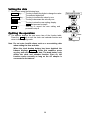
Setting the time
5
Set the time in 24-hour format using the following keys.
RANGE key ........ The key to select the digits to change the value.
The selected digits blink.
....
RE-ZERO (-)key The key to increase the value by one.
MODE (+)key........ The key to decrease the value by one.
PRINT key .......... The key to store the new setting, display
end and proceed to step 6.
.............
CAL key
The key to cancel the new setting and proceed
to step 6.
Confirming the date
6
The current date is displayed with all the digits blinking.
To change the display order of year (y), month (m) and day (d), press
the MODE key. The date is outputted in the order as specified.
When the date is correct and the operation is to be finished, press
the CAL key and proceed to step 8.
When the time is to be confirmed again, press the RANGE key
and proceed back to step 4.
When the date is not correct and is to be changed, press
the RE-ZERO key and proceed to step 7.
Note The year is expressed using a two-digit format.
For example: The year 2004 is expressed as "04".
38
Store
Proceed to date
setting mode
Setting the date
7 Set the date using the following keys.
RANGE key......... The key to select the digits to change the value.
The selected digits blink.
RE-ZERO key...... The key to increase the value by one.
MODE key .......... The key to decrease the value by one.
PRINT key .......... The key to store the new setting, display
end and proceed to step 8.
CAL key.............. The key to cancel the new setting and
proceed to step 8.
Quitting the operation
operation
8
The balance displays the next menu item of the function table.
Press the CAL key to exit the clock and calendar function and
return to the weighing mode.
Note Do not enter invalid values such as a non-existing date
when setting the time and date.
When the clock backup battery has been depleted, the
balance displays rtc pf . Under this condition, press
any key and set the time and date. The dead battery only
affects the clock and calendar function. Even so, the
function works normally as long as the AC adapter is
connected to the balance.
39
Date setting mode
Store
11. ID Number And GLP Report
The ID number is used to identify the balance when Good Laboratory Practice (GLP) is used.
The ID number is maintained in non-volatile memory even if the AC adapter is removed.
The GLP output format is selected at "GLP output (info)" of the function table and can be
output to a personal computer or printer using the RS-232C serial interface.
The GLP output format includes the balance manufacturer, model, serial number, ID
number, date, time and space for signature for weighing data, the weight used and results
for calibration or calibration test data.
The balance can output the following reports for GLP.
"Calibration report" of the calibration, using the internal mass (Calibration due to changes
in temperature and one-touch calibration.)
"Calibration report" of the calibration, using an external weight.
"Calibration test report" of the calibration test, using an external weight.
"Title block" and "End block" for the weighing data.
Calibration and calibration test data can be stored in memory to output several reports at the
same time. Refer to "12. Data Memory" for details.
For details on confirming and setting the time and date for the GH series. Refer to "10.7.
Clock and Calendar Function".
11.1.
Setting The ID Number
1
Press and hold the RANGE key until ba5fnc of the function table is displayed, then
release the key.
2
Press the RANGE key several times to display
3
Press the PRINT key. Set the ID number using the following keys.
RE-ZERO key ..... The key to set the character of the digit selected.
Refer to the display character set shown below.
........
RANGE key
The key to select the digit to change the value.
PRINT key .......... The key to store the new ID number and display ba5fnc .
CAL key ............. The key to cancel the new ID number and display ba5fnc .
4
With ba5fnc displayed, press the CAL key to return to the weighing mode.
40
id .
11.2.
GLP Report
Set the following parameters to output the report.
Refer to "15.2. Connection to peripheral equipment" for the connection of the AD-8121B.
To print the report, set the "GLP output (info)" parameter to "1" and use MODE 3 of the
AD-8121B. If MODE1 is used, select temporary dump print mode by pressing the STAT.
key of the AD-8121B.
To output the report to a personal computer using the RS-232C interface, set the "GLP
output (info)" parameter to "2".
If the time and date are not correct set the correct time and date in "Clock (Cl adj)" of the
function table.
Calibration report using the internal mass
Key operation
1 Press the CAL key to display Cal in and calibrate the balance automatically.
2 If GLP output is used, glp is displayed and the calibration report is outputted.
3 The balance returns to weighing mode after this calibration.
Setting of "info 1"
AD-8121 printer format
===========A=&=D
MODEL=====GH-300
S/N=====01234567
ID======LAB-0123
DATE==2004/07/01
TIME====12:34:56
CALIBRATED(INT.)
SIGNATURE
Setting of "info 2"
General format
Manufacturer
Model
Serial number
ID number
Date
Time
Calibration type
Signature
~~~~~~~~~~~ A~ &~ D<TERM>
MODEL~~~~~ GH-300<TERM>
S/N~~~~~ 01234567<TERM>
ID~~~~~~ LAB-0123<TERM>
DATE<TERM>
~~~~~~ 2004/07/01<TERM>
TIME<TERM>
~~~~~~~~ 12:34:56<TERM>
CALIBRATED(INT.)<TERM>
SIGNATURE<TERM>
<TERM>
<TERM>
---------------
----------------<TERM>
<TERM>
<TERM>
<TERM>
CR
LF
Space, ASCII 20h
Terminator, CR , LF or CR
Carriage return, ASCII 0Dh
Line feed, ASCII 0Ah
41
Calibration test report using an internal mass
Note Calibration test does not perform calibration.
Key operation
1 Press and hold the CAL key to display CC in and release the key.
2 CC is displayed and the balance is tested automatically.
3 Zero point is weighed and the weighing value is displayed for few seconds.
4 Internal mass is weighed and the weighing value is displayed for few seconds.
5 If GLP output is used, glp is displayed and the calibration test report is outputted.
6 The balance returns to weighing mode after this test.
Commad
This calibration test report can be performed with commad TST.
Setting of "info 1"
AD-8121 printer format
-----------A-&-D
MODEL-----GH-300
S/N-----01234567
ID------LAB-0123
DATE--2004/07/01
TIME----12:34:56
CAL.TEST(INT.)
ACTUAL
Setting of "info 2"
General format
Manufacturer
Model
Serial number
ID number
Date
Time
Calibration test type
-------0.0000--g
----+200.0002--g
Zero point value
Target weight value
TARGET
----+200.0000--g
Target weight
SIGNATURE
Signature
~~~~~~~~~~~ A~ &~ D<TERM>
MODEL~~~~~ GX-30K<TERM>
S/N~~~~~ 01234567<TERM>
ID~~~~~~ LAB-0123<TERM>
DATE<TERM>
~~~~~~ 2004/07/01<TERM>
TIME<TERM>
~~~~~~~~ 12:34:56<TERM>
CAL.TEST(INT.)<TERM>
ACTUAL<TERM>
~~~~~~~ 0.0000~~ g<TERM>
~~~~ +200.0000~~ g<TERM>
TARGET<TERM>
~~~~ +200.0000~~ g<TERM>
SIGNATURE<TERM>
<TERM>
<TERM>
---------------
---------------- <TERM>
<TERM>
<TERM>
<TERM>
CR
LF
Space, ASCII 20h
Terminator, CR , LF or CR
Carriage return, ASCII 0Dh
Line feed, ASCII 0Ah
42
Calibration report using an external
external weight
Key operation
1 Press and hold the CAL key to display Cal out and release the key.
2 Cal 0 is displayed.
3 When updating the calibration mass value, press the RANGE key and proceed to step 4.
When using preset calibration mass value, proceed to step 5.
4 Specify calibration mass value using the following keys.
RANGE key......... The key to select the blinking figure
RE-ZERO (+)key... The key to increase the value of the blinking figure.
MODE (-)key ........ The key to decrease the value of the blinking figure.
PRINT key .......... The key to store the new value.
5 When pressing the RE-ZERO key, zero point is weighed and the weighing value is displayed
for few seconds.
6 Put displayed mass on the pan. Press the PRINT key to weigh the mass and the weighing
value is displayed for few seconds.
7 If GLP output is used, glp is displayed and the calibration report is outputted.
8 The balance returns to weighing mode after this calibration.
Setting of "info 1"
AD-8121 printer format
-----------A-&-D
MODEL-----GH-300
S/N-----01234567
ID------LAB-0123
DATE--2004/07/01
TIME----12:34:56
CALIBRATED(EXT.)
CAL.WEIGHT
----+200.0000--g
SIGNATURE
Setting of "info 2"
General format
Manufacturer
Model
Serial number
ID number
Date
Time
Calibration type
Calibration weight
Signature
~~~~~~~~~~~ A~ &~ D<TERM>
MODEL~~~~~ GH-300<TERM>
S/N~~~~~ 01234567<TERM>
ID~~~~~~ LAB-0123<TERM>
DATE<TERM>
~~~~~~ 2004/07/01<TERM>
TIME<TERM>
~~~~~~~~ 12:34:56<TERM>
CALIBRATED(EXT.)<TERM>
CAL.WEIGHT<TERM>
~~~~ +200.0000~~ g<TERM>
SIGNATURE<TERM>
<TERM>
<TERM>
---------------
---------------- <TERM>
<TERM>
CR
LF
<TERM>
<TERM>
Space, ASCII 20h
Terminator, CR , LF or CR
Carriage return, ASCII 0Dh
Line feed, ASCII 0Ah
43
Calibration test report
report using an external
external weight
Note Calibration test does not perform calibration.
Key operation
1 Press and hold the CAL key to display CC out and release the key.
2 Cal 0 is displayed.
3 When updating the target value, press the RANGE key and proceed to step 4.
When using preset target value, proceed to step 5.
4 Specify calibration mass value using the following keys.
RANGE key......... The key to select the blinking figure
RE-ZERO (+)key... The key to increase the value of the blinking figure.
MODE (-)key ........ The key to decrease the value of the blinking figure.
PRINT key .......... The key to store the new value.
5 When pressing the RE-ZERO key, zero point is weighed and the weighing value is displayed
for few seconds.
6 Put displayed mass on the pan. Press the PRINT key to weigh the mass and the weighing
value is displayed for few seconds.
7 If GLP output is used, glp is displayed and the calibration test report is outputted.
8 The balance returns to weighing mode after this test.
Setting of "info 1"
AD-8121 printer format
-----------A-&-D
MODEL-----GH-300
S/N-----01234567
ID------LAB-0123
DATE--2004/07/01
TIME----12:34:56
CAL.TEST(EXT.)
ACTUAL
Setting of "info 2"
General format
Manufacturer
Model
Serial number
ID number
Date
Time
Calibration test type
-------0.0000--g
----+200.0002--g
Zero point value
Target weight value
TARGET
----+200.0000--g
Target weight
SIGNATURE
Signature
~~~~~~~~~~~ A~ &~ D<TERM>
MODEL~~~~~ GH-300<TERM>
S/N~~~~~ 01234567<TERM>
ID~~~~~~ LAB-0123<TERM>
DATE<TERM>
~~~~~~ 2004/07/01<TERM>
TIME<TERM>
~~~~~~~~ 12:34:56<TERM>
CAL.TEST(EXT.)<TERM>
ACTUAL<TERM>
~~~~~~~ 0.0000~~ g<TERM>
~~~~ +200.0002~~ g<TERM>
TARGET<TERM>
~~~~ +200.0000~~ g<TERM>
SIGNATURE<TERM>
<TERM>
<TERM>
---------------
----------------<TERM>
<TERM>
CR
LF
<TERM>
<TERM>
Space, ASCII 20h
Terminator, CR , LF or CR
Carriage return, ASCII 0Dh
Line feed, ASCII 0Ah
44
Title block and e
end
nd block
When mass values are recorded as GLP data, a "Title block" is inserted at the beginning
and an "End block" is inserted at the end of a group of mass values in the GLP report.
Notes
To output the report to an AD-8121B , use MODE 3 of the AD-8121B. If MODE1 is used,
select temporary dump print mode by pressing the STAT. key of the AD-8121B.
If the data memory function is used (except data 0), the "Title block" and "End block" can not
be output.
Key operation
1 With the weighing data displayed, press and hold the PRINT key, then release the key.
5tart is displayed. The "Title block" is output.
2 The weighing data is output according to the parameter setting of the data output mode
(prt) of the function table.
3 Press and hold the PRINT key until recend is displayed, then release the key.
The "End block" is output.
Setting of "info 1"
AD-8121 printer format
-----------A-&-D
MODEL-----GH-300
S/N-----01234567
ID------LAB-0123
DATE--2004/07/01
START
TIME----12:34:56
Title block
Manufacturer
Model
Serial number
ID number
Date
Time
WT--+123.4511--g
WT--+123.4534--g
Weighing data
WT--+123.4712--g
WT--+123.4645--g
END
TIME----12:40:15
SIGNATURE
Time
Signature
WT~~ +123.4567~~ g<TERM>
WT~~ +123.4612~~ g<TERM>
WT~~ +123.4623~~ g<TERM>
WT~~ +123.4634~~ g<TERM>
WT~~ +123.4511~~ g<TERM>
WT~~ +123.4534~~ g<TERM>
WT~~ +123.4712~~ g<TERM>
WT~~ +123.4645~~ g<TERM>
<TERM>
END<TERM>
TIME<TERM>
~~~~~~~~ 12:40:15<TERM>
SIGNATURE<TERM>
<TERM>
<TERM>
---------------
End block
<TERM>
CR
LF
~~~~~~~~~~~ A~ &~ D<TERM>
MODEL~~~~~ GH-300<TERM>
S/N~~~~~ 01234567<TERM>
ID~~~~~~ LAB-0123<TERM>
DATE<TERM>
~~~~~~ 2004/07/01<TERM>
START<TERM>
TIME<TERM>
~~~~~~~~ 12:34:56<TERM>
<TERM>
WT--+123.4567--g
WT--+123.4612--g
WT--+123.4623--g
WT--+123.4634--g
Setting of "info 2"
General format
Space, ASCII 20h
Terminator, CR , LF or CR
Carriage return, ASCII 0Dh
Line feed, ASCII 0Ah
45
----------------<TERM>
<TERM>
<TERM>
12. Data Memory
Data memory is a function to store weighing data and calibration data in memory. The data
stored in memory are available for outputting at one time to a printer or personal computer.
Weighing data
Excluding date and time
Including date and time
Up to 200 sets
Up to 100 sets
Calibration report
Internal calibration
External calibration
Calibration test report
Internal test calibration
External test calibration
12.1.
Last 50 sets
Notes on Using Data Memory
To use the memory function, set the "Data memory (data)" parameter and "Time/Date
output (5-td)" parameter of the function table. Refer to "10. The Function Table" for details
on setting the data memory.
For weighing data, the data contents to be stored and the storage capacity depend on the
"Time/Date output (5-td)" parameter setting.
Upper left of
If a different type of data exists in memory, "Clr" blinks the upper
the display
left of the display. For example, you want to store weighing data
but calibration data or unit mass data remains in memory.
Under such a condition, before storing data, delete the data in memory as follows:
Releasing "Clr"
Clr" or "err"
err"
1
Press and hold the PRINT key until SClr "n"o with "no" blinking is displayed, then release
the key.
2
Press the RE-ZERO key to display SClr "g"o with "go" blinking.
The type of data stored in memory appears in the upper left of the display as shown below:
-dd-t
Hi5
Weighing data without time and date
Weighing data with time and date
Calibration report
3
Press the PRINT key to delete all the data in memory.
4
The balance displays end and returns to the weighing mode.
46
12.2.
Data Memory for Weighing Data
The balance can store 200 sets of weighing data in memory (if time and date are added, the
balance can store 100 sets). Even if the AC adapter is removed, the data is maintained in
non-volatile memory.
It is not necessary to connect the printer or personal computer to the balance continually,
because the balance stores the weighing data in memory.
The data in memory can be outputted at one time to a printer or personal computer.
The data in memory can be displayed on the balance for confirmation.
Data (ID number, data number, time and date) to be added to the output data can be
selected in the function setting.
Storing the weighing data
Note
If "Clr" blinks in the upper left of the display, delete the data in memory.
1
Set the "Data memory (data)" parameter to "1".
2
Specify the "Time/Date output (5-td)" parameter whether time and date is to added or not.
3
The storing mode depends on the "Data output mode (prt)" parameter setting.
Four types of storing modes are available to store data.
Key mode ........................ When the PRINT key is pressed and the displayed value is
stable, the balance stores the weighing data.
.........
Auto print modes A
When the displayed value is stable and the conditions of "Auto
print polarity", "Auto print difference" and zero point (reference
value) are met, the balance stores the weighing data.
.........
Auto print modes B
When the displayed value is stable and the conditions of "Auto
print polarity", "Auto print difference" and last stable data
(reference value) are met, the balance stores the weighing data.
....
Interval memory mode Weighing data is stored at an interval specified in "Interval time
(int)". Press the PRINT key to start and stop this mode.
The data amount
in memory
Memory full
Weighing data
being displayed
Interval memory
standby indicator
Interval memory
active indicator
Data number of the data
currently displayed
Memory data
being displayed
Caution
When weighing data is being stored in memory, the data can not be output to a personal
computer using the RS-232C interface.
"fUl" indicates that memory is full or the memory capacity has been reached. More data can
not be stored unless the memory data is deleted.
47
Automatic self calibration can not be used while the interval memory mode is active.
The following commands can not be used during data storage.
Q
Query command for weighing data.
S
Query command for stable weighing data.
SI
Query command for weighing data.
SIR Query command for continuous weighing data.
Setting the function table
Parameter settings for each output mode are as follows:
Item
Data output Auto print polarity, Data memory
Interval time
Mode
mode
difference
function
Key mode
prt 0
Not used
data 1
Not used
Auto print mode A
prt 1
ap-a 0-2
data 1
ap-b 0-2
Auto print mode B
prt 2
data 1
Interval memory mode
prt 3
Not used
data 1
int 0-8
Additional parameter settings, as follows:
No
d-no 0
Data number
Yes
d-no 1
Time and date
No
5-id 0
ID number
Yes
5-id 1
Enabling the data memory function
No
Time only
Date only
Both
5-td
5-td
5-td
5-td
0
1
2
3
1
Press and hold the RANGE key until ba5fnc is displayed, then release the key.
2
Press the RANGE key several times to display dout .
3
Press the PRINT key.
4
Press the RANGE key three times to display data 0 .
5
Press the RE-ZERO key to display data 1 .
6
Press the PRINT key to store the setting.
7
Press the CAL key to return to the weighing mode.
48
Recalling the memory data
Confirm that the "Data memory (data)" parameter is set to "2".
1
Press and hold the PRINT key until reCall is displayed,
then release the key.
Indicators
2
Press the PRINT key to enter the memory recall mode. The
type of data appears in the upper left of the display as shown
to the right. Recall the data in memory using the following keys.
RE-ZERO key ..... To proceed to the next data set.
MODE key .......... To go back to the previous data set.
PRINT key .......... To transmit the current data using the
RS-232C interface.
With RANGE held down, press the CAL key
To delete the current data.
.............
CAL key
To exit the memory recall mode.
Weighing data
without time and date
3
Weighing data with
time and date
Press the CAL key to return to the weighing mode.
Transmitting all memory data at one time
Confirm that the "Serial interface (5if)" parameters are set properly.
Refer to "10. Function Table" and "15.2. Connection To Peripheral Equipment".
1
Press and hold the PRINT key until reCall is displayed,
then release the key.
2
Press the RANGE key to display out .
3
Press the PRINT key to display out "n"o with "no" blinking.
5
Press the RE-ZERO key to display out "g"o with "go" blinking.
6
Press the PRINT key to transmit all data using the RS-232C
interface.
7
The balance displays Clear when all data is transmitted.
Press the CAL key to return to the weighing mode.
Indicators
Weighing data
without time and date
Weighing data with
time and date
Deleting all memory data at one time
1
Press and hold the PRINT key until reCall is displayed, then release the key.
2
Press the RANGE key several times to display Clear .
3
Press the PRINT key to display Clr "n"o with "no" blinking.
4
Press the RE-ZERO key to display Clr "g"o with "go" blinking.
5
Press the PRINT key to delete all data
6
The balance displays end when all data is deleted. The balance displays reCall .
7
Press the CAL key to return to the weighing mode.
49
12.3.
Data Memory for Calibration and Calibration Test
Calibration data (when and how it is performed) and calibration test
data can be stored in memory.
All the data in memory is available to be output at one time to a
printer or personal computer.
Up to 50 data sets of the latest calibration or calibration test can be
stored. When the memory capacity has been reached, "fUl"
illuminates in the upper left of the display as shown below.
Indicator
Storing the calibration and calibration test data
Note If "Clr" appears blinking in the upper left of the display, delete the data in memory.
Store the calibration and calibration test data as follows:
1
Set the "Data memory (data)" parameter to "2".
2
Set the "GLP output (info)" parameter to "1" or "2".
3
With the settings above, each time calibration or calibration test is performed, the data is
stored automatically.
Transmitting the memory data
Note
Confirm that the "Serial interface (5if)" parameters are set properly.
Refer to "10. Function Table" and "15.2. Connection To Peripheral Equipment".
Confirm that the "Data memory (data)" parameter is set to "2".
out
1
Press and hold the PRINT
then release the key.
2
Press the PRINT key to display out "n"o with "no" blinking.
3
Press the RE-ZERO key to display out "g"o with "go" blinking.
4
Press the PRINT key to transmit all memory data using the RS-232C interface.
5
The balance displays Clear when all memory data is output. Press the CAL key to
return to the weighing mode.
key until
is displayed,
In the upper left
of the display
Deleting data stored in memory
1
Press and hold the PRINT key until out is displayed, then release the key.
2
Press the SAMPLE key to display Clear .
3
Press the PRINT key to display Clr "n"o with "no" blinking.
4
Press the RE-ZERO key to display Clr "g"o with "go" blinking.
5
Press the PRINT key to delete all data.
6
The balance displays out when all the data has been deleted.
Press the CAL key to return to the weighing mode.
50
In the upper left
of the display
13. Underhook
The underhook can be used for magnetic materials or density measurement. The built-in
underhook is revealed by removing the cover plates on the bottom of the balance. Use the
underhook as shown below.
Caution
Do not apply excessive force to the underhook.
When not in use, attach the cover plate to
prevent dust from getting into the balance.
Do not push the underhook upward
When turnig over the balance, the weighing pan,
pan support breeze breakring and dust plate fall
off. Remove them first.
While removing the cover, weighing error may
occur, because draft breezes into the internal
balance. Arrange the room condition.
1
Remove the cover on the bottom of the balance.
2
Hang your weighing pan to the underhook.
Place the balance on the film table.
Bottom
Underhook
Cover
Film table
Weighing pan
51
14. Density Measurement
Measurement
The balance is equipped with a density mode. It calculates the density of a solid using the
mass value of a sample in air and the mass value in liquid.
Note
The density mode was not selected for use when the balance was shipped from the factory.
To use the mode, change the function table and activate the density mode.
When the density mode is selected, the response adjustment function can not be used.
Minimum display is 0.0001 g while density mode.
Formula to obtain the density
The density can be obtained by the following formula.
Where
ρ : Density of a sample
A
A : Mass value of a sample in air
ρ=
x ρ0
B : Mass value of a sample in liquid
A- B
ρ0 : Density of a liquid
Prior to measurement: Changing the function table
Prior to measurement, change the function table as follows:
1
Selecting the density mode.
The density mode is available as one of the weighing units.
Select it by pressing the MODE key. To use the mode, select it (unit of Unit d .) in the
function table. Refer to "5.2. Changing Units".
2
Selecting a way to set the density of a liquid.
Select the liquid density input method from the function table below.
Note
The function table is available only when the density mode (d5fnc) is selected. d5fnc is
displayed next 5if when density mode is active at Unit.
Class
d5 fnc
Density function
Item and Parameter
Description
ldin
0 Water temperature
Liquid density input
1 Liquid density
is factory setting.
52
Entering the density of a liquid
Two ways to set the density of a liquid are available in the function table, "Liquid density
input (ldin): by entering the water temperature or by entering the density directly.
1
Press the MODE key as necessary to select the density mode.
When the density mode begins, "g (gram)" is displayed and the
processing indicator ( ) blinks.
2
The water temperature currently set (unit:°C, factory setting : 25°C) is
displayed. Use the following keys to change the value.
Entering the water temperature (ldin 0)
RE-ZERO (+)key... The key to increase the temperature by one degree.
(0°C is displayed after 99°C)
MODE (-)key ........The key to decrease the temperature by one degree.
(99°C is displayed after 0°C)
PRINT
CAL
key..........The key to store new water temperature, display end and
return to the density mode. Proceed to Step 1.
key.............The key to cancel the change and return to the density mode.
Proceed to Step 1.
The relation between the water temperature and density
°C
0
10
20
30
40
50
60
70
80
90
+0
0.99984
0.99970
0.99820
0.99565
0.99222
0.98804
0.98320
0.97777
0.97180
0.96532
+1
0.99990
0.99961
0.99799
0.99534
0.99183
0.98758
0.98268
0.97720
0.97117
0.96465
+2
0.99994
0.99949
0.99777
0.99503
0.99144
0.98712
0.98216
0.97662
0.97054
0.96397
+3
0.99996
0.99938
0.99754
0.99470
0.99104
0.98665
0.98163
0.97603
0.96991
0.96328
+4
0.99997
0.99924
0.99730
0.99437
0.99063
0.98618
0.98110
0.97544
0.96927
0.96259
+5
0.99996
0.99910
0.99704
0.99403
0.99021
0.98570
0.98055
0.97485
0.96862
0.96190
+6
0.99994
0.99894
0.99678
0.99368
0.98979
0.98521
0.98001
0.97425
0.96797
0.96120
+7
0.99990
0.99877
0.99651
0.99333
0.98936
0.98471
0.97946
0.97364
0.96731
0.96050
+8
0.99985
0.99860
0.99623
0.99297
0.98893
0.98422
0.97890
0.97303
0.96665
0.95979
+9
0.99978
0.99841
0.99594
0.99259
0.98849
0.98371
0.97834
0.97242
0.96600
0.95906
Entering the density directly (ldin 1)
The density currently set (unit : g / cm3, factory setting : 1.0000g / cm3) is displayed.
Use the following keys to change the value.
The range to set the density is 0.0000g / cm3 to 1.9999g / cm3.
RE-ZERO (+)key ... The key to set the value of the digit selected.
RANGE (-)key ....... The key to select the digit to change the value.
PRINT
CAL
key .......... The key to store the change, display end and return to the density
mode. Proceed to Step 1.
key ............. The key to cancel the change and return to the density mode. Proceed to
Step 1.
53
Measuring the density
Note If the liquid temperature or the type of liquid is changed during measurement,
input again the value of the liquid density as necessary.
Density display is four decimal places. Minimum display can not change with
the RANGE key.
1
Denisty is displayed after "Mass measurement in air" and "Mass measurement in liquid".
The procedure of each measurements is as follows:
From "Entering the
density of a liquid"
Enter the density mode that "g (gram)" is
displayed and the processing indicator (
)
blinks. Put nothing on both pan and press the
Weighing in air.
RE-ZERO key to display zero.
g lights.
blinks.
2
Put the sample on the pan in air.
If the weighing value is stored or outputted,
press the PRINT key to store it after a stable
weighing value is displayed.
Press the RANGE key to decide weighing
value in air and proceed to next step.
Note If negative value or E (out of range) is
displayed, the RANGE key is inactive.
3
Move the sample to the pan in liquid.
If the weighing value is stored or outputted,
press the PRINT key to store it after a stable
weighing value is displayed.
Press the RANGE key to decide weighing
value in liquid and proceed to next step.
Note If E (out of range) is displayed, the RANGE
key is inactive.
4
If the density value is stored or outputted, press
the PRINT key to store it.
Press the RANGE key to measure other
sample and proceed to step 2.
5
If the liquid temperature or the type of liquid is
changed during measurement, input again the
value of the liquid density as necessary.
6
Press the
modes.
MODE
key to proceed to other
54
Put sample to the pan in air
Weighing in air.
g lights.
blinks.
Output or store
Move sample from the pan in
air to the pan in liquid
Weighing in liquid.
g lights.
lights.
Output or store
Density display.
g turns off.
lights.
Output or store
Remove sample
15. Standard Input & Output Interface
15.1.
RSRS-232C Interface
The balance is a DCE device. Connect the balance to a personal computer (DTE) using a
straight through cable.
Transmission system : EIA RS-232C
Transmission form
: Asynchronous, bi-directional, half duplex
Transmission rate
: 10 times/second or 5 times/second (same as data refresh rate)
Data format
: Baud rate : 600, 1200, 2400, 4800, 9600, 19200bps
Data bits : 7 or 8 bits
Parity
: Even, Odd (Data bits 7 bits)
None
(Data bits 8 bits)
Stop bit : 1 bit
RS-232C
Code
: ASCII
-5V to -15V
+5V to +15V
Data bits
Stop bit
Start bit
Parity bit
D-Sub 25 pin assignments
Pin No. Signal name Direction
Description
1
No connection
2
TXD
Output Transmit data
3
RXD
Input
Receive data
4
No connection
5
SG
Signal ground
6
DSR
Output Data set ready
7
RTS
Input
Request to send
8
CTS
Output Clear to send
9
No connection
Singal names of the balance side are the same as
the DTE side with TXD and RXD reversed.
Balance side
DCE
Computer side
DTE
TXD 2
+5V
3.3kΩ
#4-40UNC
RXD
RXD 3
TXD
RTS 7
RTS
CTS 8
CTS
DSR 6
SG
DSR
5
SG
Inside of balance
Terminals sample
55
15.2.
Connection to peripheral equipment
Connection To The ADAD-8121B Printer
Preset the following parameters to use the AD-8121B printer.
Function setting
Description
dout prt 0 to 3
Selects a print mode.
dout ap-p 0 to 2
Selects the polarity for the auto print mode.
dout ap-b 0 to 2
Selects the auto print difference.
dout pU5e 0,1
Selects data output pause.
5if
bp5 2
Factory setting 2400 bps
5if
btpr 0
Factory setting 7 bits, Even parity check
5if
Crlf 0
Factory setting CR, LF
5if
Ct5 0
Factory setting Inhibit the use of CTS and RTS control
When "MODE 1" or "MODE 2" of the AD-8121B printer is used
Function setting
Description
dout 5-td 0
Factory setting
Not to output the time and date.
dout 5-id 0
Factory setting
Not to output the ID number.
dout at-f 0
Factory setting
Not to use auto feed.
5if
type 0
Factory setting
A&D standard format
When "MODE 3" of the AD-8121B printer is used.
Function setting
Description
dout 5-td 0 to 3
Outputs the time and date as necessary.
dout 5-id 0,1
Outputs the ID number as necessary.
dout at-f 0,1
Uses auto feed as necessary.
5if
type 1
DP format
When data is transmitted continuously.
When all memory data is transmitted at one time.
Function setting
Description
dout pU5e 1
Uses pause.
Notes
The printer performs as follows, depending on the data memory setting.
Setting
Output data
data 0
The weighing data
data 1
The weighing data stored in memory
data 2
The calibration report stored in memory
Refer to "11.2. GLP Report" for print samples.
56
Connection To A Computer And The Use Of WinCT
WinCT
The balance is of the DCE type (Data Communication Equipment), which can be connected
to a personal computer using the RS-232C interface. Before connection, read the personal
computer manual thoroughly. Use a standard DCE cable for connection (cable type:
straight-through).
Using Windows Communication Tools Software (WinCT)
When Windows is used as an operating system in a personal computer, the provided
WinCT software can be used to transmit the weighing data to the personal computer.
The WinCT software has two communication methods: "RsCom" and "RsKey". Refer to the
WinCT instruction manual
RsCom
RsCom can transmit commands to control the balance.
RsCom can make bi-directional communication between the balance and a personal
computer using the RS-232C interface.
RsCom can display or store the data using a text file format. RsCom can also print the data
using a printer connected to the personal computer.
When several ports of a personal computer have balances connected, can communicate
with each balance simultaneously.
RsCom can share a personal computer with other application software.
RsCom can receive the balance GLP report.
RsKey
RsKey can transmit the weighing data output from the balance directly to other application
software such as Microsoft Excel.
RsKey can be used with most application software.
RsKey can receive the balance GLP report.
Using the WinCT software, the balance can do the following:
Analyzing the weighing data and the statistics with "RsKey"
The weighing data can be input directly into an Excel worksheet. Then, Excel can analyze
the data to obtain total, average, standard deviation, maximum and minimum value, and
display them in a graph.
Controlling the balance using commands from a personal computer
By using "RsCom", the personal computer sends commands such as "re-zero" or "send
weighing data" to the balance and controls the balance.
Printing the balance GLP report using your printer
The balance GLP report can be printed using a printer connected to the personal computer.
Receiving weighing data at a certain interval
The weighing data can be received at a certain interval and data characteristic with elapsed
time can be obtained.
Using the balance memory function
The data can be stored in the balance’s memory. Of the data stored, the weighing data and
calibration data can be transmitted to a personal computer at one time.
Using a personal computer as an external indicator
With the "RsKey" test mode function, a personal computer can be used as an external weight
indicator for the balance. (To do this, set the balance data output mode to stream mode.)
57
15.3.
15.3.1.
Commands
Command List
Note A command has a terminator added, that is specified using "5if Crlf" of the
function table, and is sent to the balance.
Commands to query weighing data
C
Cancels the S or SIR command.
Q
Requests the weighing data immediately.
S
Requests the weighing data when stabilized.
SI
Requests the weighing data immediately.
SIR
Requests the weighing data continuously.
Commands to control the balance
Same as the CAL key.
CAL
Turns the display off.
OFF
Turns the display on.
ON
Same as the ON:OFF key
P
Same as the PRINT key
PRT
Same as the RE-ZERO key
R
Same as the RANGE key.
RNG
Perform calibration test.
TST
Same as the MODE key
U
Commands to request data
Requests the identification number.
?ID
Request the serial number of the balance.
?SN
Request the model name of the balance.
?TN
58
15.3.2.
Acknowledge Code And Error Codes
When the "Serial interface function (5if)" parameter is set to "erCd 1", the balance outputs
<AK> code or error code to each command as follows:
<AK> (06h)
Acknowledge in ASCII code.
When the balance receives a command to request data and can not process it, the balance
transmits an error code (EC, Exx).
When the balance receives a command to request data and can process it, the balance
outputs the data.
When the balance receives a command to control the balance and can not process it, the
balance transmits an error code (EC, Exx).
When the balance receives a command to control the balance and can process it, the
balance transmits the acknowledge code.
Among commands to control the balance, the following transmit the acknowledge code
both when the balance receives the command and when the balance has
accomplished the command. If the command can not be processed properly, the
balance transmits an error code (EC, Exx). This error can be released using the CAL
command.
CAL command (Calibration command using internal mass)
ON command (Display ON command)
P command (Display ON/OFF command)
R command (RE-ZERO command)
TST command (Calibration test command)
When a communication error has occurred due to external noise, or a parity error has
occurred due to transmission error, the balance transmits an error code. In this case, send
the command again.
xx is error code number.
15.3.3.
Control Using CTS And RTS
Depending on the "Ct5" parameter of "Serial interface (5if)", the balance performs as follows:
Ct5 0
Regardless of whether the balance can receive a command or not, the balance keeps the
CTS line HI. The balance outputs data regardless of the condition of the RTS line.
Ct5 1
The CTS line is kept Hi normally. When the balance can not receive the next command
(Example: while the balance is processing the last command), the balance sets the CTS line
to Lo. The balance confirms the level of the RTS line before outputting a set of data. If the
RTS level is Hi, the balance outputs data. If the RTS level is Lo, data is not output (The data
is canceled).
15.3.4.
Settings Related To RSRS-232C
Concerning the RS-232C, the balance has two functions: "Data output (dout)" and "Serial
interface (5if)". Set each function as necessary.
59
15.3.5.
Command Sample
This example is used the "erCd 1" of "5if" so that <AK> (06h) code is outputted.
Example of ON command (turning on the balance)
Computer
Time
Balance
Standby mode
ON commnd
Response of recieving a command
All segments
All segemnts are displayed
Finishing command
Zero display
Example of R command (Re(Re-zeroing the display)
Computer
Time
Balance
Weighing mode
R command
Response of recieving a command
In process
Finishing command
Zero display
60
Example of CAL command (Calibration with internal mass)
Computer
Time
Balance
Zero display
CAL command
Response of recieving a command
Finishing command
Zero display
Example of Error code
This example is an error of R command. "erCd 1" is used. The balance transmits error code
when received command can not be achieved.
Computer
Time
Balance
Unstable weighigng value
R command
Response of recieving a command
In process
When R command can not be
achieved due to unsable weighing.
Error code
When CAL command is received,
the balance returns to weighing
mode
CAL command
Finishing command
Weighing mode
61
16. Maintenance
16.1.
Treatment Of The Balance
Clean the balance with a lint free cloth that is moistened with warm water and a mild
detergent.
Do not use organic solvents to clean the balance.
Do not disassemble the balance. Contact the local A&D dealer if the balance needs
service or repair.
Use the original packing material for transportation.
Consider "3. Precautions" when operation the balance.
16.2.
Display
Error Codes
Error code Description
Stability error
The balance can not stabilize due to an environmental
problem. Check around the pan. Prevent vibration, drafts,
EC,E11
temperature changes, static electricity and magnetic fields,
from influencing the balance.
To return to the weighing mode, press the CAL key.
Internal mass error
Applying the internal mass does not yield a change in the
EC,E16 mass value as specified.
Confirm that there is nothing on the pan and perform the
weighing operation from the beginning again.
Internal mass error
The internal mass application mechanism does not function
EC,E17
properly. Perform the weighing operation from the beginning
again.
Calibration weight error
The calibration weight is too heavy. Confirm the calibration
EC,E20
mass value. Press the CAL key to return to the weighing
mode.
Calibration weight error
The calibration weight is too light. Confirm the calibration
EC,E21
mass value. Press the CAL key to return to the weighing
mode.
Overload error
A sample beyond the balance weighing capacity has been
placed on the pan. Remove the sample from the pan.
Weighing pan Error
The mass value is too light.
Confirm that the weighing pan is properly installed and
calibrate the balance.
62
Display
Error code Description
Sample mass error
The balance can not store the sample for the counting mode
or for the percent mode because it is too light.
Use a larger sample.
Unit mass error
The sample unit mass for the counting mode is too light.
Storing and using it for counting will cause a counting error.
Add samples to reach the specified number and press the
PRINT key. Pressing the PRINT key without adding samples
will shift the balance to the counting mode. But, to acquire
accurate weighing, be sure to add samples.
Automatic response adjustment zero error
The automatic response adjustment can not be performed
because there is something on the pan. Clear the pan. Press
the CAL key to return to the weighing mode.
Automatic response adjustment unstable error
The automatic response adjustment can not be performed
because the mass value is unstable.
Check the ambient conditions such as breeze, vibration and
(Check NG)
magnetic fields, also check the weighing pan.
Press the CAL key to return to the weighing mode.
Clock battery error
The clock backup battery has been depleted.
Press any key and set the time and date. The clock and
calendar function works normally as long as the AC adapter
is connected to the balance. If this error appears frequently,
contact the local A&D dealer.
Memory full
The amount of weighing data in memory has reached the
(Blinking)
maximum capacity. Delete data in memory to store new data.
For details, refer to "12. Data Memory".
Memory full
The amount of calibration or calibration test data in memory
has reached the maximum capacity (50 sets).
(Illuminated)
The data in memory will be deleted automatically to store
new data. For details, refer to "12. Data Memory".
Memory type error
Type of memory set in the function table and type of data
stored are different. For details, refer to "12. Data Memory".
Communications error
EC,E00 A protocol error occurred in communications.
Confirm the format, baud rate and parity.
Undefined command error
EC,E01 An undefined command was received.
Confirm the command.
63
Display
Other error code
16.3.
Error code Description
Not ready
A received command can not be processed.
Example:
The balance received a "Q" command, but not in the
EC,E02
weighing mode.
The balance received a "Q" command while processing a
RE-ZERO command. Adjust the delay time to transmit a
command.
Timeout error
If the timeout parameter is set to "t-Up1", the balance did not
EC,E03
receive the next character of a command within the time limit
of one second. Confirm the communication.
Excess characters error
EC,E04 The balance received excessive characters in a command.
Confirm the command.
Format error
A command includes incorrect data.
EC,E06 Example:
The data is numerically incorrect.
Confirm the command.
Parameter setting error
EC,E07 The received data exceeds the range that the balance can
accept. Confirm the parameter range of the command.
If an error described above can not be released or other
errors are displayed, contact the local A&D dealer.
Other Display
Advise
When this indicator blinks, automatic self calibration is required. The
indicator blinks when the balance detects changes in ambient
temperature. If the balance is not used for several minutes with this
indicator blinking, the balance performs automatic self calibration. The
blinking period depends on the operating environment.
The balance can be used while this indicator is blinking. We
recommend that you perform automatic self calibration for precision
weighing.
64
16.4.
Checking The Balance Performance And Environment
Environment
The balance is a precision instrument. When the operating environment or the operating
method is inadequate, correct weighing can not be performed. Place a sample on the pan
and remove it, and repeat this several times. if the balance seems to have a problem with
repeatability or to perform improperly, check as described below. If improper performance
persists after checking, contact the local A&D dealer for repair.
Checking that the operating environment or weighing
method is proper
Operating environment
environment
Is the weighing table solid enough?
Is the balance level?
Is the operating environment free from vibration and drafts?
Is there a strong electrical or magnetic noise source such as a motor near the balance?
Weighing method
Does the weighing pan touch the rim or anything? Is the weighing pan and pan support
installed correctly?
Is the RE-ZERO key pressed before placing a sample on the weighing pan?
Is the sample placed in the center of the weighing pan?
Is the fine range breeze break ring installed on weighing of which the minimum display is
0.01 mg for GH-252 and GH-202?
Has the balance been calibrated using the internal mass (one-touch calibration)?
Has the balance been warmed up for one hour before weighing?
Sample and container
container
Has the sample absorbed or lost moisture due to the ambient conditions such as
temperature and humidity?
Has the temperature of the container been allowed to equalize to the ambient temperature?
Is the sample charged with static electricity?
Is the sample of magnetic material such as iron? There are cautions to weigh magnetic
materials.
Checking that the balance performs properly
Check the balance performance using an external weight. Be sure to place the weight in the
center of the weighing pan.
Check the balance repeatability, linearity and calibrated value using external weights with a
known value.
16.5.
Asking For Repair
If the balance needs service or repair, contact your local A&D dealer.
The balance is a precision instrument. Use much care when handling the balance and
observe the following when transporting the balance.
Use the original packing material for transportation.
Remove the draft gate, weighing pan and pan support from the main unit.
65
17. Specifications
GH-120
GH-200
GH-300
Weighing capacity
120 g
220 g
320 g
Maximum display
120.0084 g
220.0084 g
320.0084 g
Minimum display
0.1 mg
Repeatability
(Standard deviation)
0.1 mg
0.2mg
Linearity
±0.2 mg
±0.3 mg
GH-202
GH-252
220 g
250 g
51 g
101 g
220.0084 g 250.0084 g
51.00009 g 101.00009 g
0.1 mg
0.01 mg
0.1 mg
0.02 mg
0.03 mg
±0.2 mg
±0.03 mg
±0.10 mg
Approx. 3.5 seconds
Approx. 8 seconds
Percent
mode
Counting
mode
Stabilization time
Approx. 3.5 seconds
(Typical at FAST)
Sensitivity drift,
±2 ppm/°C
10°C to 30°C / 50°F to 86°F
Operating environment
5°C to 40°C, 85%RH or less (No condensation)
Display refresh rate
5 times/second or 10 times/second
Minimum unit
0.1 mg
mass
Number of
10, 25, 50 or 100 pieces
samples
Minimum 100%
10.0 mg
reference mass
Minimum 100%
0.01 %, 0.1 %, 1 % (Depends on the reference mass stored.)
display
Interface
RS-232C with Windows Communication Tools Software WinCT
300g
200g
200g
200g
External calibration
100g
100g
100g
100g
weight
50g
50g
20g
Weighing pan
φ90 mm
External dimensions
217(W) x 442(D) x 316(H) mm
Power consumption: Approx. 11VA (supplied to the AC adapter )
Power supply &
Confirm that the adapter type is correct for the local voltage and
AC adapter type
power receptacle type.
Mass
Approx. 8.2 kg
Operating environment does not include excessive change of ambient tempeature and
humidity, vibration, draft, magnetic fields and static electricity.
The internal mass may change due to corrosion or other damage caused by the operating
environment, or due to aging. Check the internal mass periodically and correct the internal
mass value if necessary.
66
17.1.
External Dimensions
Dimensions
Unit: mm
67
17.2.
Options and Peripheral Instruments
ADAD-8121B Printer
Compact dot-matrix printer
Statistical function, clock and calendar function,
interval print function, graphic print function, dump print
mode
5 x 7 dots, 16 characters per line
Print paper (AX-PP143, 45 (W) x 50 (L) mm , ø65 mm)
AC adapter or alkaline battery
ADAD-1653 Density Determination Kit
Weigh in air
x water density = sample density
Weigh in water - Weigh in the air
Example
10.0000 g
x 0.9970 g/cm3 = 21.4 g/cm3
10.0000 g − 9.5334
Temperature
0°C
10°C
20°C
30°C
Water density
0.99984 g/cm3
0.99970 g/cm3
0.99820 g/cm3
0.99565 g/cm3
External key Plug AXAX-T-314A314A-S
This plug produces the same operations as
pressing the RE-ZERO and PRINT keys. It
enables remote control of the balance using
an external key.
This operation must connect the GND line to
the PRINT or RE-ZERO line for at least 100
mili-seconds.
External key Plug
AX-T-314A-S
Terminal
Foot swtch AXAX-SW128
The switch can be used to connect the
external key plug and used to the RE-ZERO
and PRINT keys.
Note When using the foot switch, connect
AX-SW128 and AX-T-314A-S by yourself.
68
Foot switch
AX-SW128
Other accessories
Order code
AD-1682
AD-1683
AD-8524A/B
AD-8920
Name and description
Rechargeable Battery
This option allows use of the balance in a place where AC power is
not available.
Static Eliminator
This option can be used to eliminate the static electricity of weighing
samples.
Keyboard Adapter
This option can be used to connect the balance to a personal
computer with appropriate OS and applications.
Remote Display
This option can be connected to the balance using the RS-232C
interface.
69
18. Terms/Index
18.1.
Terms
Calibration
Adjustment of the balance so that it can weigh accurately.
Calibration weight
A weight used for calibration
Data number
Numbers assigned sequentially when weighing data or unit weight is
stored.
Digit
The minimum weighing value available. Used for the balance, one digit
is the smallest mass that can be displayed.
Environment
Ambient conditions such as vibration, drafts, temperature, static
electricity and magnetic fields which affect the weighing operation.
External weight
The weight that you have.
GLP
Good Laboratory Practice.
GMP
Good Manufacturing Practice
Internal mass
Built-in calibration weight
ISO
International Organization for Standardization
Repeatability
Variation in measured values obtained when the same mass is placed
and removed repetitively. Usually expressed as a standard deviation.
Example: Standard deviation = 1 digit: This means that measured
values, obtained when the same sample is placed and removed
repetitively, fall within ±1 digit in the frequency of about 68%.
Re-zero
To set the display to zero.
Sensitivity drift
An affect that a change in temperature causes to the weighing data.
Expressed as a temperature coefficient.
Example: Temperature coefficient = 2 ppm/°C : If a load is 10 g and the
temperature changes by 10°C, the value displayed changes by the
following value.
0.0002%/°C x 10°C x 10g = 0.0002 g
Stabilization time
Time required after a sample being placed, until the stabilization
indicator illuminates and the weighing data is displayed.
Tare
To cancel the mass value of a container which is not to be included in
the weighing data. Normally, refers to an operation of placing a
container and setting the display to zero.
Target mass
An external weight used for calibration test
Zero point
A weighing reference point. Usually refers to the value displayed when
nothing is on the weighing pan.
70
18.2.
%
Index
Ct5
CTS, RTS control..........................30
CTS
.......................................................59
-dWeighing data with calender ........46
data
Data memory ................................28
Data number......................................................69
Digit
.......................................................69
d-no
Data number output......................29
dout
Data output........................28, 29, 32
d5 fnc
Density function ............................30
d-t
Weighing data ...............................46
Dump print .......................................................33
-e
Weighing pan Error.......................62
e
Overload error...............................62
EC,E00
Communications error ..................63
EC,E01
Undefined command error ...........63
EC,E02
Not ready.......................................64
EC,E03
Timeout error.................................64
EC,E04
Excess characters error ...............64
EC,E06
Format error ..................................64
EC,E07
Parameter setting error.................64
EC,E11
Stability error .................................62
EC,E16
Internal mass error........................62
EC,E17
Internal mass error........................62
EC,E20
Internal mass error........................62
EC,E21
Internal mass error........................62
erCd
AK, Error code ..............................30
error 1 Stability error .................................62
error 6 Internal mass error........................62
error 7 Internal mass error........................62
Error code .......................................................62
External weight............................................19, 69
FAST
.......................................................17
FCC
......................................................... 4
fUl
Memory full........................47, 50, 63
GLP
.......................................................69
GMP
.......................................................69
Hi5
Calibration report ..........................46
id
ID number setting .........................30
ID Number .................................................35, 40
info
GLP output ....................................29
int
Interval time...................................29
KF format .......................................................34
ldin
Liquid density input .......................30
lo
Sample mass error .......................63
MID.
.......................................................17
MT format .......................................................34
Numerical format ...............................................34
out
Report output ..........................49, 50
p5
internal mass correction ...............26
pnt
Decimal point ..........................28, 31
p-on
Auto display-ON......................28, 31
prt
Data output mode ...................28, 32
pU5e
Data output pause ........................29
recend
End bolck ......................................45
Repeatability................................................66, 69
Re-zero
.......................................................69
Unit of percent mode .................... 16
CAL key..................................... 9, 30
MODE key....................................... 9
ON OFF key.................................... 9
PRINT key................................. 9, 30
RANGE key .............................. 9, 30
RE-ZERO key........................... 9, 30
Data number .......................9, 35, 47
Interval memory mode ............. 9, 47
Prior notice indicator................. 9, 20
Process indicator ............................ 9
Space mark.... 36, 41, 42, 43, 44, 45
Stabilization indicator..........9, 12, 30
Standby indicator ............................ 9
Response indicator ............. 9
A&D format ....................................................... 33
AC adapter ................................................... 5, 66
ACAI Function ................................................... 15
Accessory ....................................................... 68
AD-1682 ....................................................... 68
AD-8121B Printer......................................56, 67
AD-8524 ....................................................... 68
AD-8920 ....................................................... 68
AK code
....................................................... 59
ap-b
Auto print difference ...................28, 32
ar-d
Zero after output ........................... 29
ap-p
Auto print polarity....................28, 32
at-f
Auto feed....................................... 29
ba5fnc
Environment display ...............27, 28
bp5
Baud rate....................................... 29
btpr
Data bit, parity bit .......................... 29
C5 in
Internal mass correction............... 24
-Cal e
Calibration weight error ................ 62
Cal e
Calibration weight error ................ 62
Cal in
One-touch calibration ................... 20
Cal out
Calibration using an external weight .. 22
Calibration ...........................................19, 23, 69
Calibration test .................................................. 19
CC in
Calibration test.............................. 21
CC out
Calibration test.............................. 23
CH 0
Response error............................. 63
Cl adj
Clock ............................................... 28
Clr
Initializing the balance .................. 26
Cond
Condition...........................17, 28, 31
Crlf
Terminator ..................................... 29
C5 in
Internal mass correction............... 30
CSV format ....................................................... 35
71
5-td
Time/Date output ..........................29
Tare
.................................................12, 69
Target mass .......................................................69
trc
Zero tracking ...........................28, 31
t-Up
Timeout..........................................30
type
Data format ...................................29
PCS
Unit of counting mode...................14
Unit
.............................................9, 10, 37
Unit
Unit ................................................30
WinCT
Communication Tools ...................57
Zero point .......................................................69
RsCom
....................................................... 57
RsKey
....................................................... 57
rtc
Clock battery error ........................ 63
RTS
....................................................... 59
5-id
ID number output.......................... 29
5if
Serial interface.............................. 29
SLOW
....................................................... 17
5pd
Display refresh rate ................28, 31
Stabilization time .........................................66, 69
5tart
Title block ...................................... 45
5t-b
Stability band width.................28, 31
72