1
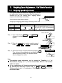
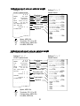
GX-K series
GX-8K, GX-12K, GX-30K
GX-8K2, GX-20K, GX-32K
GF-K series
GF-8K, GF-12K, GF-30K
GF-8K2, GF-20K, GF-32K
WM+PD4000775A
Instruction manual
GX-K series, GF-K series
This Manual and Marks
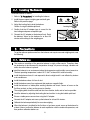
All safety messages are identified by the following, “WARNING” or “CAUTION”, of
ANSI Z535.4 (American National Standard Institute: Product Safety Signs and
Labels). The meanings are as follows:
WARNING
CAUTION
A potentially hazardous situation which, if not avoided,
could result in death or serious injury.
A potentially hazardous situation which, if not avoided,
may result in minor or moderate injury.
This is a hazard alert mark.
This manual is subject to change without notice at any time to improve the
product.
The contents of the product specifications and this manual are subject to
change without any obligation on the part of the manufacturer.
Under the copyright laws, the software (program) described in it are copyrighted,
with all rights reserved.
The software may be installed into one computer and may not be installed into
other computers without the prior written consent of A&D Company. Copying
includes translation into another language, reproduction, conversion, photocopy
and offer or loan to another person.
Microsoft, Windows, Word, Excel is a registered trademark of the Microsoft
Corporation.
2004
All rights reserved.
No part of this publication may be reproduced, transmitted, transcribed, or
translated into any language in any form by any means without the written
permission of A&D Company Ltd.
Contents
Basic Operation
1.
1-1.
1-2.
1-3.
Introduction ....................................................................................................................... 3
About This Manual ....................................................................................................... 3
Features........................................................................................................................ 3
Compliance................................................................................................................... 4
2-1.
Unpacking And Installing The Balance ........................................................................... 5
Installing The Balance.................................................................................................. 6
3-1.
3-2.
3-3.
3-4.
Precautions....................................................................................................................... 6
Before Use.................................................................................................................... 6
During Use.................................................................................................................... 7
After Use ....................................................................................................................... 8
Power Supply ............................................................................................................... 8
4-1.
Display Symbols and Key Operation.............................................................................. 9
Smart Range Function...............................................................................................10
5-1.
5-2.
Weighing Units ............................................................................................................... 11
Units ............................................................................................................................ 11
Changing the Units.....................................................................................................14
6-1.
6-2.
6-3.
6-4.
6-5.
Weighing.........................................................................................................................15
Basic Operation (Gram Mode) ..................................................................................15
Counting Mode (PCS)................................................................................................16
Percent Mode (%) ......................................................................................................18
Animal Weighing Mode (Hold Function)...................................................................18
Accumulation Function...............................................................................................19
2.
3.
4.
5.
6.
Adapting To The Environment
7.
7-1.
7-2.
7-3.
Weighing Speed Adjustment / Self Check Function ....................................................21
Weighing Speed Adjustment .....................................................................................21
Self Check Function With Response Adjustment For The GX-K Series ................22
Self Check Function For GF-K Series ......................................................................22
8-1.
8-2.
8-3.
8-4.
8-5
8-6.
Calibration.......................................................................................................................23
Calibration Group .......................................................................................................23
Automatic Self Calibration For The GX-K Series .....................................................24
One-Touch Calibration For The GX-K Series...........................................................25
Calibration Using An External Weight .......................................................................26
Calibration Test Using An External Weight ...............................................................27
Correcting The Internal Mass Value Of The GX-K Series .......................................28
8.
Selecting Functions
9.
9-1.
9-2.
Function Switch And Initialization..................................................................................30
Permit Or Inhibit..........................................................................................................30
Initializing The Balance ..............................................................................................31
10.
10-2.
10-3.
10-4.
Function Table ................................................................................................................32
Details Of The Function Table ...................................................................................34
Description Of The Class "Environment, Display"....................................................37
Description Of The Item "Data Output Mode" ..........................................................39
Instruction manual
1
GX-K series, GF-K series
10-5.
10-6.
10-7.
10-8.
Description Of The Item "Data Format" ....................................................................40
Data Format Examples ..............................................................................................43
Clock And Calendar Function....................................................................................45
Comparator Function .................................................................................................46
11.
11-1.
11-2.
ID Number And GLP Report..........................................................................................53
Setting The ID Number ..............................................................................................53
GLP Report.................................................................................................................54
12.
12-1.
12-2.
12-3.
12-4.
12-5.
12-6.
12-7.
12-8.
Data Memory..................................................................................................................57
Notes on Using Data Memory ...................................................................................57
Data Memory for Weighing Data...............................................................................58
Data Memory for Calibration and Calibration Test ...................................................61
Data Memory for Unit Mass in the Counting Mode..................................................62
Data Memory for Comparator Settings .....................................................................65
Data Memory for Tare Value......................................................................................68
Data Memory: Quick Selection Mode .......................................................................71
Data Memory: Confirmation and Storage Mode.......................................................72
13.
Underhook ......................................................................................................................74
14.
Programmable Unit ........................................................................................................75
15.
Density Measurement....................................................................................................76
Interface And Communication
16.
16-1.
16-2.
Standard Input & Output Interface ................................................................................80
RS-232C And External Contact Input .......................................................................80
Connection to peripheral equipment .........................................................................82
17.
17-1.
17-2.
17-3.
17-4.
Commands .....................................................................................................................84
Command List ............................................................................................................84
Acknowledge Code And Error Codes.......................................................................85
Control Using CTS And RTS .....................................................................................86
Settings Related To RS-232C ...................................................................................86
Maintenance
18.
18-1.
Maintenance...................................................................................................................87
Treatment Of The Balance ........................................................................................87
19.
19-1.
19-2.
19-3.
19-4.
Troubleshooting..............................................................................................................88
Checking The Balance Performance And Environment..........................................88
Error Codes ................................................................................................................89
Other Display..............................................................................................................91
Asking For Repair.......................................................................................................91
20.
20-1.
20-2.
Specifications..................................................................................................................92
External Dimensions ..................................................................................................94
Options and Peripheral Instruments..........................................................................95
21.
21-1.
21-2.
Terms/Index....................................................................................................................97
Terms...........................................................................................................................97
Index............................................................................................................................99
2
1. Introduction
This manual describes how the balances of the GX-K series and GF-K series work and
how to get the most out of them in terms of performance.
Read this manual thoroughly before using the balance and keep it at hand for future
reference.
1-1. About This Manual
This manual consists of the following five parts:
Basic operation .........................Describes precautions, the balance's construction and basic
operation.
Adapting to the environment .....Describes response (and stability) adjustment to adapt to
the environment where there is vibration or drafts, the way to
maintain weighing precision in a variation of ambient
temperature, calibration and calibration test.
Functions....................................Describes functions of the balance.
RS-232C serial interface .........Describes the RS-232C serial interface and external contact
input. The RS-232C serial interface can communicate with a
computer that requests weighing data and controls the
balance. This RS-232C interface is for use with a computer
or printer. The external contact input commands the balance
re-zeroing and data output.
Maintenance .............................Describes maintenance, error codes, troubleshooting,
specifications and options.
1-2. Features
Large vacuum fluorescent display (VFD), easy to read.
Dust-tight and protected against water jets, allows washing with water. A waterproof
RS-232C cable (GX-07K) is available as an option.
Built-in calibration weight (hereinafter referred to as the internal mass) of the GX-K
series, allows easy calibration, adjustment and maintenance of the balance.
Automatic self calibration of the GX-K series, using the internal mass, adapting to
changes in temperature.
Automatic self-check function to check itself by one key operation.
The response speed of the GX-K series, adapting to drafts and vibration after
self-checking the balance.
3
High response speed: The time to read a displayed value after a sample is placed on
the pan has been shortened by using a super hybrid sensor (SHS).
Approximately 1.5 seconds when FAST is selected for the response rate.
Data memory function stores weighing data, calibration data or unit mass in the
counting mode. It can also store tare values or upper and lower limit values for the
comparator function.
Interval memory mode is provided to store the weighing data periodically.
Good laboratory practice (GLP) data can be output using the standard RS-232C serial
interface.
GX-K series has a built-in clock and calendar that can add the time and date to the output data.
Comparator Indicators, displaying the comparison results, H I , OK or LO .
Capacity Indicator, displaying the weight value in percentage relative to the weighing capacity.
Hold function, provided for weighing a moving object such as an animal.
Multiple weighing units with most of the common units used around the world.
Density mode, for calculating the density of a solid.
Accumulation function, adding the weight values and outputting the sum.
Standard RS-232C serial interface to communicate with a computer.
Windows communication tools software (WinCT) to allow easy communication with Windows.
Reference card, provided for a quick reference to the balance operation.
Underhook, available as an option, for measuring density and weighing magnetic materials.
Comparator output (GX-04K) and analog voltage output (GX-06K) are available as options.
Breeze break (AX-GXK-31), can be used for a precision weighing, is provided for GX-8K,
GX-8K2, GF-8K and GF-8K2.
1-3.
1-3-1.
Compliance
Compliance With FCC Rules
Please note that this equipment generates, uses and can radiate radio frequency
energy. This equipment has been tested and has been found to comply with the limits
of a Class A computing device pursuant to Subpart J of Part 15 of FCC rules. These
rules are designed to provide reasonable protection against interference when
equipment is operated in a commercial environment. If this unit is operated in a
residential area, it may cause some interference and under these circumstances the
user would be required to take, at his own expense, whatever measures are necessary
to eliminate the interference.
(FCC = Federal Communications Commission in the U.S.A.)
1-3-2.
Compliance With EMC Directives
This device features radio interference suppression in compliance with valid EC
Regulation 89/336/EEC.
Note: The device may be adversely affected under extreme electromagnetic influences.
4
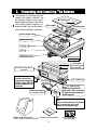
2. Unpacking And Installing The Balance
The balance is a precision instrument.
Unpack the balance carefully. Keep
the packing material to be used for
transporting the balance in the future.
The packing contents depend on the
balance model. See the illustrations to
confirm that everything is contained.
Weighing pan
Pan support
Handling hole
A clear display cover
Bubble sprit level
Display
Keys
Reference card
Leveling foot
Draft gate
Remove the gate
when cleaning.
RS-232C and external
terminals
Terminal cover
Note
Cover the terminal or
connect the waterproof
RS-232C cable (GX-07K)
to keep waterproof and
dustproof.
AC adapter jack
Grounding
terminal
Note AC adapter plug
Insert the plug into the
jack firmly. The connection
is tight to keep waterproof
and dustproof.
Position of placing
AC adapter labels
AC adapter plug
Note
Please confirm that the AC adapter
type is correct for your local
voltage and receptacle type.
Breeze beak provided for
Windows communication
GX-8K, GX-8K2, GF-8K and GF-8K2.
5
AC adapter labels
tools software
2-1. Installing The Balance
Install the balance as follows:
1
Refer to "3. Precautions" for installing the balance.
Bubble sprit level
2
Install the pan support, weighing pan and draft gate.
Refer to the previous page.
Good
3
Adjust the leveling feet to level the balance.
Confirm it using the bubble spirit level.
No good
Leveling foot
4
Confirm that the AC adapter type is correct for the
local voltage and power receptacle type.
5
Connect the AC adapter to the balance firmly. Earth
the balance. Warm up the balance for at least 30
minutes with nothing on the weighing pan.
Grounding
(Earth)
To AC adapter
3. Precautions
To get the optimum performance from the balance and acquire accurate weighing data, note
the following:
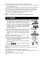
3-1. Before Use
The maximum resolution of the precision balance is eighty million counts. Therefore, there
are tendencies to be influenced by temperature change, air pressure change, vibration and
drafts where the balance is placed.
Install the balance in an environment where the temperature and humidity are not excessive.
The best operating temperature is about 20°C / 68°F at about 50% relative humidity.
Install the balance where it is not exposed to direct sunlight and it is not affected by heaters
or air conditioners.
Install the balance where it is free of dust.
Install the balance away from equipment that produces magnetic fields.
Install the balance in a stable place avoiding vibration and shock. Corners of rooms on the
first floor are best, as they are less prone to vibration.
The weighing table should be solid and free from vibration, drafts and as level as possible.
Level the balance by adjusting the leveling feet and confirm it using the bubble spirit level.
Ensure a stable power source when using the AC adapter.
Connect the AC adapter and warm up the balance for at least 30 minutes.
Calibrate the balance periodically for accurate weighing.
When the balance is installed for the first time or has been moved, warm up the balance for
at least 6 hours to allow the balance to reach equilibrium with the ambient temperature, and
then perform calibration before use.
6
The meaning of IP-65 is "No ingress of dust. Projected against water jets".
If a powerful water jet is used or the balance is immersed in water, it may cause a damage
that is due to ingress of water.
Confirm that "the plug is inserted firmly into the jack" and "the terminal is covered using the
waterproof cover or the waterproof RS-232C cable (GX-07K)", when using the balance.
Use the waterproof option cable GX-07K, when the RS-232C interface is used with IP-65.
AX-KO1710-200, a standard RS-232C cable, is not waterproof or dustproof.
Confirm that the weighing pan does not touch to rim.
Do not install the balance where flammable or corrosive gas is present.
3-2. During Use
Discharge static electricity from the material to be weighed
(hereinafter referred to as the sample). When a sample could
have a static charge, the weighing data is influenced. Try to keep
the ambient humidity above 45%RH or use the metal shield case.
Material case
Charged
sample
This balance uses a strong magnet as part of the balance
Grounding
assembly, so please use caution when weighing magnetic
materials such as iron. If there is a problem, use the underhook on
the bottom of the balance to suspend the material away from the
influence of the magnet.
Magnetic
Eliminate any temperature difference between the sample and the material
environment. When a sample is warmer (cooler) than the ambient
Draft
temperature, the sample will be lighter (heavier) than the true
weight. This error is due to a rising (falling) draft around the
20°C 40°C
sample.
Weighing Pan
Make each weighing gently and quickly to avoid errors due to
changes in the environmental conditions.
Shock
Do not drop things upon the weighing pan, or place a sample on
the pan that is beyond the balance weighing capacity. Place the
sample in the center of the weighing pan.
Do not use a sharp instrument such as a pencil to press the keys.
Use your finger only.
Press the RE-ZERO
possible errors.
key before each weighing to prevent
Calibrate the balance periodically so as to eliminate possible errors.
Take into consideration the affect of air buoyancy on a sample when more accuracy is
required.
It is possible to check the reference card for principle operation.
Prevent foreign matter, such as powder, liquid and metal, from invading the area around
the weighing pan.
Use the "breeze break" for a precision weighing.
7
3-3. After Use
Avoid mechanical shock to the balance.
Do not disassemble the balance. Contact the local A&D dealer if the balance needs service
or repair.
Do not use organic solvents to clean the balance. Clean the balance with a lint free cloth that
is moistened with warm water and a mild detergent.
Do not allow the balance to be immersed in water. Even though the balance complies with
IP code, the balance will not withstand being completely immersed in water.
The weighing pan, pan support and draft gate can be removed to clean the balance. Clean
by splashing with water.
Use the waterproof option RS-232C cable GX-07K, when RS-232C interface is used with
IP-65. AX-KO1710-200, a standard RS-232C cable, is not waterproof or dustproof.
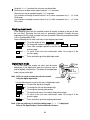
3-4. Power Supply
Do not remove the AC adapter while the internal mass is in motion, for example, right
after the AC adapter is connected, or during calibration using the internal mass.
If the AC adapter is removed under the conditions described above, the internal mass
will be left unsecured, that may cause mechanical damage when the balance is moved.
Before removing the AC adapter, press the ON:OFF key and confirm that zero is
displayed.
When the AC adapter is connected, the balance is in the standby mode if the standby
indicator is on. This is a normal state and does not harm the balance. For accurate
weighing, keep the AC adapter connected to the balance and AC power unless the
balance is not to be used for a long period of time.
8
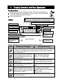
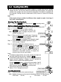
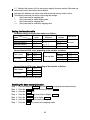
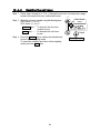
4. Display Symbols and Key Operation
Key Operations
Key operation affects how the balance functions. The basic key operations are:
"Press and release the key immediately" or "Press the key" are normal operation.
= normal key operation during measurement
"Press and hold the key".
Displays memory data information
Displays the weighing data relative to the weighing capacity
in percentage, in weighing mode. (Capacity indicator)
Display
Weighing speed indicator (Response indicator)
NET indicator
Animal mode indicator
Processing indicator
Comparator indicators
Stabilization indicator
Units
Standby indicator
of power supply
Interval memory
Standby indicator
The current data number
Weighing data or
stored data
Processing indicator
Prior notice indicator
of automatic self
calibration
Blinking indicators
Interval memory,
active indicator
Each key, when pressed or when pressed and held, functions as follows:
Key
When pressed and released
When pressed and held
Turns the display ON and OFF. The standby indicator is displayed when the display
is turned off. The weighing mode is enabled when the display is turned on. This key
is available anytime. Pressing the key during operation will interrupt the operation
and turn the display OFF.
In the weighing mode, turns the
minimum weighing value ON and OFF.
Enters the function table mode.
In the counting or percent mode, enters
Refer to "10. Function Table".
the sampling mode.
Switches the preset weighing units
Performs weighing speed adjustment
stored in the function table. Refer to "5
(response adjustment) and self check.
Weighing Units".
Performs calibration using the internal
Displays other items of the calibration
mass for GX-K series.
menu.
No function at the factory setting.
Stores the weighing data in memory or
By changing the function table:
outputs to a printer or personal computer
Outputs "Title block" and "End block"
depending on the function table settings.
for GLP report.
(Factory setting = output)
Displays the data memory menu.
Sets the display to zero.
9
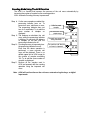
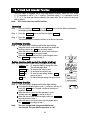
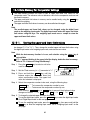
4-1. Smart Range Function
The GX-32K, GF-32K, GX-8K2 and GF-8K2 are equipped with two ranges of "precision
range" of a higher resolution and "standard range" of normal resolution.
The range is switched automatically depending on the value displayed.
Pressing the RE-ZERO key allows weighing in the precision range, regardless of the
tare value. (Smart range function)
The range can be fixed to the standard range, by pressing the SAMPLE key.
Note
Once the range is switched to the standard range, it will not switch to the precision
range automatically even when the displayed value becomes within the precision
range value. Press the RE-ZERO or SAMPLE key to use the precision range again.
Example
GX-32K or GF-32K, precision range = 6.1 kg x 0.1g, standard range = 31 kg x 1 g.
Weighing Pan
Step 1 Press the RE-ZERO key.
The balance will start weighing, using the
precision range.
Precision range
Step 2 Place a container on the weighing pan.
When the weighing value exceeds
the precision range, the range will be
switched to the standard range.
Tare (Container)
Standard range
Step 3 Press the RE-ZERO key.
The balance will be switched to the
precision range.
Precision range
Step 4 Place a sample on the pan.
When the weighing value is within the
precision range, the balance will perform
a weighing using the precision range.
Sample
Precision range
Precision range/standard range value
Precision range
(after RE-ZERO key is pressed)
Standard range
GX-32K / GF-32K
GX-8K2 / GF-8K2
Up to 6100.9 g
Up to 2100.09 g
6101 to 31008
10
g
2100.1 to 8100.8 g
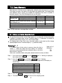
5. Weighing Units
5-1. Units
With the balance, the following weighing units and weighing modes are available :
Counting mode
g
kg
DS
Percent mode
%
OZ
Lb
pcs
MS
t
TL
GN
L
dwt
OZ
OZt
mom
ct
Density mode (To use this mode, it must be stored in the function table as described on the next
page. For details about this mode, refer to "15. Density Measurement".
To select this mode, press the MODE key until the processing indictor blinks with
the unit "g" displayed. " " appears only when the density value is displayed.)
Programmable-unit. No unit displayed. Refer to "13. Programmable Units" for details.
A unit or mode can be selected and stored in the function table as described in "5-2.Changing
the Units".
If a weighing mode (or unit of weight) has been turned off, that mode or unit will be missing in
the sequence. Tael has four varieties, one of which can be selected and installed at the factory.
To select a unit or mode for weighing, press the MODE key.
For details about the units and modes, see the table below:
Name (unit, mode)
Gram
kilogram
Counting mode
Percent mode
Ounce (Avoir)
Pound
Abbreviation
g
kg
pcs
%
OZ
Lb
t
MS
Conversion factor
1g=
1g
1000 g
28.349523125 g
453.59237 g
1 Lb = 16 oz,
1 oz = 28.349523125 g
31.1034768 g
0.2 g
3.75 g
1.55517384 g
0.06479891 g
37.7994 g
37.429 g
37.5 g
31.25 g
11.6638038 g
4.6875 g
DS
-
Pound/Ounce
L
Troy Ounce
Metric Carat
Momme
Pennyweight
Grain (UK)
Tael (HK general, Singapore)
Tael (HK jewelry)
Tael (Taiwan)
Tael (China)
Tola (India)
Messghal
OZt
ct
mom
dwt
Density mode
Display
Function table
(Storing mode)
pcs
l0
OZ
GN
TL
is used to
show the density
Programmable-unit (Multi-unit)
Mlt
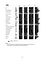
Note The unit Grain is not available for the GX-32K and GF-32K.
11
-
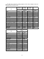
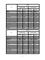
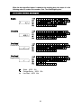
The tables below indicate the weighing capacity and the minimum display for each unit,
depending on the balance model.
Unit
GX-12K
GF-12K
GX-20K
GF-20K
GX-30K
GF-30K
Capacity
Gram
Kilogram
Ounce (Avoir)
Pound
Pound/Ounce
Troy Ounce
Metric Carat
Momme
Pennyweight
Grain (UK)
Tael (HK general, Singapore)
Tael (HK jewelry)
Tael (Taiwan)
Tael (China)
Tola (India)
Messghal
Unit
Gram
Kilogram
Ounce (Avoir)
Pound
Pound/Ounce
Troy Ounce
Metric Carat
Momme
Pennyweight
Grain (UK)
Tael (HK general, Singapore)
Tael (HK jewelry)
Tael (Taiwan)
Tael (China)
Tola (India)
Messghal
12000.0
12.0000
423.290
26.4555
26L 7.29
385.810
60000.0
3200.00
7716.2
185188
317.465
320.605
320.000
384.000
1028.82
2560.00
21000.0
21.0000
740.755
46.2970
46L 4.75
675.165
105000.0
5600.00
13503.3
324080
555.565
561.060
560.000
672.000
1800.44
4480.00
GX-8K
GF-8K
Minimum
Capacity
display
8100.00
0.01
8.10000
0.00001
285.7190
0.0005
17.85745
0.00005
17L 13.719
0.001
260.4210
0.0005
40500.00
0.05
2160.000
0.005
5208.42
0.01
125002.2
0.2
214.2890
0.0005
216.4095
0.0005
216.0000
0.0005
259.2000
0.0005
694.456
0.001
1728.000
0.005
12
31000.0
31.0000
1093.495
68.3435
68L 5.49
996.675
155000.0
8266.65
19933.5
478404
820.120
828.235
826.665
992.000
2657.80
6613.35
Minimum
display
0.1
0.0001
0.005
0.0005
0.01
0.005
0.5
0.05
0.1
2
0.005
0.005
0.005
0.005
0.01
0.05
GX-8K2
GF-8K2
Unit
Standard range
Precision range
Minimum
display
0.1
0.0001
0.005
0.0005
0.01
0.005
0.5
0.05
0.1
2
0.005
0.005
0.005
0.005
0.01
0.05
Capacity
Gram
Kilogram
Ounce (Avoir)
Pound
Pound/Ounce
Troy Ounce
Metric Carat
Momme
Pennyweight
8100.00
8.1000
285.720
17.8575
17L 13.72
260.420
40500.0
2160.00
5208.4
Grain (UK)
125002
Tael (HK general, Singapore)
214.290
Tael (HK jewelry)
216.410
Tael (Taiwan)
216.000
Tael (China)
259.200
Tola (India)
694.46
Messghal
1728.00
Capacity
2100.00
2.10000
74.0755
4.62970
4L 10.075
67.5165
10500.00
560.000
1350.33
32408.0
55.5565
56.1060
56.0000
67.2000
180.044
448.000
Minimum
display
0.01
0.00001
0.0005
0.00005
0.001
0.0005
0.05
0.005
0.01
0.2
0.0005
0.0005
0.0005
0.0005
0.001
0.005
GX-32K
GF-32K
Unit
Standard range
Minimum
display
1
0.001
0.05
0.005
0.1
0.05
5
0.5
1
0.05
0.05
0.05
0.05
0.1
0.5
Capacity
Gram
Kilogram
Ounce (Avoir)
Pound
Pound/Ounce
Troy Ounce
Metric Carat
Momme
Pennyweight
Grain (UK)
Tael (HK general, Singapore)
Tael (HK jewelry)
Tael (Taiwan)
Tael (China)
Tola (India)
Messghal
31000
31.000
1093.50
68.345
68L 5.5
996.65
155000
8266.5
19933
820.10
828.25
826.65
992.00
2657.8
6613.5
13
Precision range
Capacity
6100.0
6.1000
215.170
13.4480
13L 7.17
196.120
30500.0
1626.65
3922.4
161.380
162.975
162.665
195.200
522.99
1301.35
Minimum
display
0.1
0.0001
0.005
0.0005
0.01
0.005
0.5
0.05
0.1
0.005
0.005
0.005
0.005
0.01
0.05
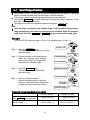
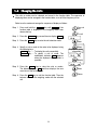
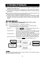
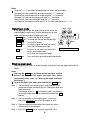
5-2. Changing the Units
The units or modes can be selected and stored in the function table. The sequence of
displaying them can be arranged in the function table, so as to fit the frequency of use.
Select a unit or mode and arrange the sequence of display as follows:
Step 1 Press and hold the SAMPLE key until ba5fnc of the
function table is displayed in the weighing mode, then
release the key.
Press and
hold
To unit
Step 2 Press the SAMPLE key several times to display Unit .
Step 3 Press the PRINT key to enter the unit selection mode.
Step 4 Specify a unit or mode in the order to be displayed using
the following keys.
SAMPLE key ....... To display the units sequentially.
RE-ZERO key...... To specify a unit or mode. The
stabilization indicator
appears
when the displayed unit or mode is
specified.
Step 5 Press the PRINT key to store the units or modes.
The balance displays end and then displays the next
menu item of the function table.
Step 6 Press the CAL key to exit the function table. Then the
balance returns to the weighing mode with the selected
unit.
14
Enter
Select
Displays the units
sequentially.
Specify
Store
Return
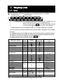
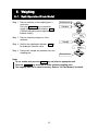
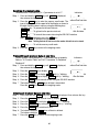
6. Weighing
6-1. Basic Operation (Gram Mode)
Step 1 Place a container on the weighing pan, if
necessary.
Press the RE-ZERO key to cancel the
weight (tare). The balance displays 00 g .
(The decimal point position depends on the
balance model.)
Weighing pan
Container
Step 2 Place a sample on the pan or in the
container.
Sample
Step 3 Wait for the stabilization indicator
be displayed. Read the value.
to
Step 4 Remove the sample and container from the
weighing pan.
Remove them
Notes
To use another unit, press the MODE key and select an appropriate unit.
Press the SAMPLE key to turn on or off the minimum weighing value.
The weighing data can be stored in memory. Refer to "12. Data Memory" for details.
15
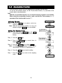
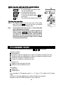
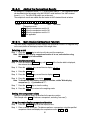
6-2. Counting Mode (PCS)
This is the mode to determine the number of objects in a sample based on the standard
sample unit mass. The unit mass means an average mass of the samples. The smaller the
variation in the samples, the more accurate the count will be. The balance is equipped with
the Automatic Counting Accuracy Improvement (ACAI) function to improve the counting
accuracy.
Note
If the sample unit mass variable, the difference from sample to sample, is too large, it
may cause a counting error.
Selecting The Counting Mode
Step 1 Press the MODE key to select the unit pcs (counting mode).
Storing A Sample Unit Mass (Weighing Input Mode)
Step 2 Press the SAMPLE key to enter the sample unit mass storing mode.
Step 3 To select the number of samples using the
SAMPLE key. It may be set to 10, 25, 50 or 100.
Advise A greater number of samples will yield a more
accurate counting result.
Weighing pan
Step 4 Place a container on the weighing pan, if necessary.
Press the RE-ZERO key to cancel the weight (tare).
The number specified in step 3 appears.
Example: 25 0 pcs is displayed if 25 is selected in step 3.
Container
Step 5 Place the number of samples specified on the pan.
In this example, 25 pieces.
25 Samples
Step 6 Wait for the stabilization indicator to come on.
Press the PRINT key to calculate and store the unit
mass. Then the balance displays 25 pcs and is set to
count samples with this unit mass. (The sample unit
mass stored, even if the AC adapter is removed, is
maintained in non-volatile memory.) To improve the
accuracy of the unit mass, go to step 8.
Notes
If the balance judges that the mass of the samples is too light and
can not be stored as the unit mass, it displays lo .
If the balance judges that the mass of the samples is too light to
acquire accurate weighing, it displays an error requiring the
addition of more samples to the specified number.
Example: 150 - pcs appears, requiring 25 more samples. Add 25
samples and press the PRINT key. When the unit mass is
stored correctly, the balance goes to the counting mode.
The unit mass can be input numerically.
Refer to "12-4-1. Storing the unit mass".
Place samples
Counting Operation
Step 7 Place the samples to be counted on the pan.
Counting result
Advise Multiple unit masses can be stored in the balance. Refer to "12. Data Memory".
GX-K series........ 50 units,
GF-K series ......... 20 units
16
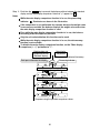
Counting Mode Using The ACAI Function
The ACAI is a function that improves the accuracy of the unit mass automatically by
increasing the number of samples as the counting process.
ACAI: Automatic Counting Accuracy Improvement
Step 8 If a few more samples are added, the
processing indicator turns on. To
prevent an error, add three or more.
The processing indicator does not
turn on if overloaded. Try to add the
same number of samples as
displayed.
Step 9 The balance re-calculates the unit
mass while the processing indicator
is blinking. Do not touch the balance
or samples on the pan until the
processing indicator turns off.
Step 10 Counting accuracy is improved when
the processing indicator turns off.
Each time the above operation is
performed, a more accurate unit
mass will be obtained. There is no
definite upper limit of ACAI range for
the number of samples exceeding
100. Try to add the same number of
samples as displayed.
Step 11 Remove all the samples used in
ACAI and proceed with the counting
operation using the improved unit
mass.
From step 7
Add a few more
samples.
The mark turns on at
proper range.
The mark turns on and off
during calculation.
The mark turns off after the
unit mass is improved.
Renew
Note ACAI will not function on the unit mass entered using the keys, or digital
input mode.
17
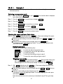
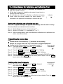
6-3. Percent Mode (%)
The percent mode displays the weighting value in percentage compared to a 100%
reference mass and is used for target weighing or checking the sample variance.
Selecting The Percent Mode
Step 1 Press the MODE key to select the unit %
(Percent mode). If the percent mode can not be
selected, refer to "5. Weighing Units".
Storing The 100% Reference Mass
Step 2 Press the SAMPLE key to enter the 100%
reference mass storing mode.
Even in the storing mode, pressing the MODE
key will switch to the next mode.
Step 3 Place a container on the weighing pan, if
necessary. Press the RE-ZERO key to cancel the
weight (tare). The balance displays 100 0 %.
Pan
Container
Step 4 Place the sample to be set as the 100%
reference mass on the pan or in the container.
Step 5 Press the PRINT key to store the reference
mass. The balance displays 10000 %. (The
decimal point position depends on the reference
value. The reference mass stored, even if the
AC adapter is removed, is maintained in
non-volatile memory.)
Note
If the balance judges that the mass of the
sample is too light to be used as a reference, it
displays lo .
100%
mass
Step 6 Remove the sample.
Place sample
Reading The Percentage
Step 7 Place a sample to be compared to the reference
mass on the pan. The displayed percentage is
based on the 100% reference mass.
Percentage
6-4. Animal Weighing Mode (Hold Function)
This is the mode to weigh a moving object such as an animal, even when the display of the
weighing data fluctuates. The hold function allows the average weight of the animal to be
displayed. To use the hold function, set the function in the function table. Refer to "10.
Function Table" and "10-3. Description Of The Class "Environment, Display" " for details.
18
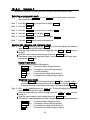
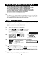
6-5. Accumulation Function
The accumulation function sums the weighing data and displays the total value.
To use the accumulation function, set the "Accumulation function (add)" parameter of the
function table as described below.
Note
While the accumulation function is in use, the data memory function is not available.
When using the accumulation function, make sure that the "Data memory (data)"
parameter of the function table is set to "0".
Selecting The Unit
Weighing mode
Step 1 Press the MODE key to select a unit to be
used for accumulation.
Note While the accumulation function is in use, unit
selection using the MODE key is not available.
Selected unit
Press and
hold the key
Setting The Function Table
Step 2 Press and hold the SAMPLE key until ba5fnc
of the function table is displayed, then release
the key.
Step 3 Press the PRINT key.
Step 4 Press the SAMPLE
display add 0 .
Press the key
several times
key several times to
Step 5 Press the RE-ZERO key to display add 1 .
Note To disable the accumulation function, set the
"Accumulation function (add)" parameter to "0".
Step 6 Press the PRINT key to store the setting.
Step 7 Press the CAL key to return to the weighing
mode.
19
Weighing mode
Using The Accumulation Function
Use the following keys to operate the accumulation function.
MODE key ...... Displays the weighing data and the total value alternately each time it is pressed.
While the accumulation function is in use, the unit can not be changed.
RE-ZERO key .. Sets the display to zero while the weighing data is displayed.
Deletes the total value while the total value is displayed.
PRINT key ....... Outputs and adds the weighing data while the weighing data is displayed.
Outputs the total value while the total value is displayed.
Step 1 Press the RE-ZERO key to zero the
display.
Accumulation
number
Step 2 Place a sample on the pan. The weight
value is displayed.
Step 3 Press the PRINT key. The weight
value is added to the total and is
output.
The accumulation number at the upper
left of the display increases by one.
Accumulation
number
Step 4 Repeat steps 1 to 3, when
accumulating more data.
Step 5 Press the MODE key to display the
total value.
Output
ST,+012345.6 g
Accumulation value
Outputting the value
Step 6 Press the PRINT key to output the
total value.
Step 7 Press the RE-ZERO key to delete the
total value.
Output
TOTAL(N=012)
ST,+012345.6 g
Notes And Displaying Or Outputting An Overloaded Total
The output format depends on the function table setting.
While the accumulation function is in use, the data memory
function is not available.
To disable the accumulation function, set the
Data number is above 99
"Accumulation function (add)" parameter to "0".
When the "Data number output (d-no)" parameter is set to
"1", the accumulation number will be output before the
Output TOTAL(N=--)
Accumulation data is
weighing data.
OL,+9999999E+19 g
overloaded.
20
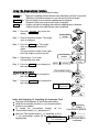
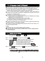
7. Weighing Speed Adjustment / Self Check Function
7-1. Weighing Speed Adjustment
This function detects the influence on weighing that is caused
by drafts and/or vibration at the place where the balance is
installed and sets the following three weighing speeds
(response characteristics) automatically.
Weighing speeds
The function has three rates as follows:
Changing the weighing speed changes the display refresh rate.
Indicator Parameter Weighing Speed Stability
Display refresh rate
FAST
Cond 0
Fast response, Sensitive value If the weighing speed is changed as follows:
MID. or SLOW FAST =10 times/second
MID.
Cond 1
FAST MID. or SLOW = 5 times/second
Slow
response,
Stable
value
SLOW
Cond 2
Press and hold
Step 1 Press and hold the MODE key until RESPONSE is
displayed. And then, press the MODE key again
quickly.
Release
Press again
Step 2 Press the MODE key to select a weighing speed.
Either FAST , MID. or SLOW can be selected.
Select a parameter
with pressing it.
Release and wait
Step 3 After a few seconds of inactivity the balance displays end .
Then, it returns to the weighing mode and displays the
updated response indicator. The response indicator
remains displayed for a while.
Note
The weighing speed adjustment can be changed at "Condition (Cond)" of
"Environment, Display (ba5fnc)" in the function table. Refer to "10. Function
Table" for details.
To set a refresh rate of 5 times/second when the response rate is FAST or
10 times/second when the response rate is MID. or SLOW , change the
"Display refresh rate (5pd)" parameter of "Environment, Display (ba5fnc)" in
the function table.
21
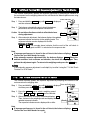
7-2. Self Check Function With Response Adjustment For The GX-K Series
This function automatically updates the response adjustment by analyzing the influence of
the environment on the weighing data and also self-checks the balance performance using
the internal mass.
Press and hold
Step 1 Press and hold the MODE key until RESPONSE is displayed,
and then release the key.
Step 2 The balance automatically starts to check the balance
performance and sets the response characteristic.
Caution Do not allow vibration or drafts to affect the balance
during adjustment.
Release
Result
Step 3 After automatic adjustment, the balance displays the updated
response indicator and returns to the weighing mode. The
response indicator remains displayed for a while.
Example of display
MID. and OK : The example above indicates that the result of the self check is
good and MID. is selected as the response rate..
Note
If improper performance is found in the self check, the balance displays CH no .
Contact the local A&D dealer for repair.
If the automatic response adjustment fails, the balance displays CH ng . Check the
ambient conditions such as breeze and vibration, also check the weighing pan. Then,
perform the adjustment again. To return to the weighing mode, press the CAL key.
Advise
If the automatic response adjustment is not helpful, try to refine it using the "7-3. Self Check
Function For GF-K Series".
7-3. Self Check Function For GF-K Series
This function manually updates the response adjustment by analyzing the influence of the
environment on the weighing data.
Press and hold
Step 1 Press and hold the MODE key until RESPONSE is displayed.
And then, press the MODE key again quickly.
Step 2 Press the MODE key to select a weighing speed.
Either FAST , MID. or SLOW can be selected.
Step 3 After a few seconds of inactivity the balance displays end .
Then, it returns to the weighing mode and displays the
updated response indicator.
The response indicator remains displayed for a while.
Release
Result
Note
If improper performance is found in the self check, the balance displays CH no .
Contact the local A&D dealer for repair.
22
8. Calibration
8-1. Calibration Group
The balance has the following modes as a calibration group.
Calibration
Automatic self calibration (Calibration due to changes in temperature for GX-K series)
Calibration using the internal mass for GX-K series (One-touch calibration)
Calibration using an external weight
Calibration Test
Calibration test using an external weight (Calibration test does not perform calibration)
Correction of the internal mass value
Terms
The following terms are defined as follows:
Internal mass
= Built-in calibration weight (GX-K series only)
External weight = A weight that you have. Referred to as a calibration weight when
used for calibration.
Calibration weight
=
A weight used for calibration
Target weight
= An external weight used for calibration test
Caution
The GF-K series does not perform "automatic self calibration" and "one-touch calibration
using the internal mass", as it does not include an internal mass.
Calibration adjusts the balance for accurate weighing.
Besides periodic calibration and before each use, perform calibration when:
the balance is installed for the first time.
the balance has been moved.
the ambient environment has changed.
Do not allow vibration or drafts to affect the balance during calibration.
To output the data for GLP using the RS-232C interface, set "GLP output (info)" of
"Data output (dout)". Refer to "10. Function Table". The time and date can be added to
the GLP report concerning the GX-K series. If the time or date is not correct, adjust them.
Refer to "10-7 Clock and Calendar Function".
Calibration test is available only when "GLP output (info)" of "Data output ( dout )" is set to
"1" or "2",
For GX-K series, the calibration and calibration test data can be stored in memory. To store
them, set "Data memory (data)" to "3". Refer to "12. Data Memory" for details.
For GF-K series, the calibration and calibration test data is not stored in memory.
The value of the internal mass may change due to aging, corrosion or other damage
caused by the operating environment. Check the internal mass periodically. Correct the
internal mass value as necessary.
23
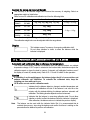
Caution On Using An External Weight
The accuracy of an external weight can influence the accuracy of weighing. Select an
appropriate weight as listed below:
Select a mass for calibration and calibration test from the following table.
GX-8K
GX-8K2
Model
GF-8K
GF-8K2
Usable calibration weight
Adjustable range
2kg, 3kg, 4kg, 5kg, 6kg, 7kg, 8kg
-0.15g ~ +0.15 g
GX-12K
GF-12K
5kg, 10kg
GX-20K
GF-20K
10kg, 20kg
-1.5g ~ +1.5 g
GX-30K
GF-30K
20kg, 30kg
GX-32K
GF-32K
The calibration weight in bold type: factory setting
The calibration weight value can be adjusted within the range above.
Display
This indicator means "In process of measuring calibration data".
Do not allow vibration or drafts to affect the balance while the
indicator is displayed.
8-2. Automatic Self Calibration For The GX-K Series
Automatic self calibration due to changes in temperature
This function automatically calibrates the balance when the balance detects an ambient
temperature change. If GLP output is selected in the function table, the balance outputs the
calibration report or stores the data in memory. Automatic self calibration functions even if
the display is turned off (standby state). Refer to "9-1. Permit Or Inhibit" for the operation.
Caution
If something is on the weighing pan, the balance judges that it is in use and does not
perform automatic self calibration. To maintain the calibrated state, keep the
weighing pan clear while not in use.
GF-K series can not use this calibration mode.
Indicates that the balance detects a change in ambient temperature and
automatic self calibration will start. If the balance is not used for a few
minutes with this indicator blinking, the balance performs automatic self
calibration. The blinking duration depends on the environment.
Indicates that the balance is measuring calibration data. Do not allow
vibration or drafts to affect the balance while this indicator is displayed.
After calibration, the balance returns to indicate the previous display.
Note
The balance can be used while the indicator blinks. But, it is recommended that to
maintain the accuracy, stop using the balance and confirm that there is nothing on the
pan and allow the balance to perform self calibration.
24
8-3. One-Touch Calibration For The GX-K Series
Calibration using the internal mass for The GX-K series
This function calibrates the balance using the internal mass. The only operation required is
to press the CAL key.
Caution
GF-K series can not use this calibration mode.
Step 1 Connect the AC adapter and warm up the balance for at least 30 minutes with
nothing on the weighing pan.
Step 2 Press the CAL key.
Step 3 The balance displays Calin and performs calibration using the internal mass. Do
not allow vibration or drafts to affect the balance.
Step 4 The balance displays end after calibration. If the "GLP output (info)" parameter of
the function table is set to "1" or "2", the balance displays glp and outputs the
"calibration report" using the RS-232C interface or stores the data in memory. Refer
to "11-2. GLP Report" and "Data memory (data)" of the function table for details.
Step 5 The balance will automatically return to the weighing mode after calibration.
About the internal mass
The value of the internal mass may change due to aging, corrosion or other damage caused
by the operating environment. Check the internal mass periodically. Correct the internal
mass value as necessary. Refer to "8-6. Correcting the internal mass value".
To maintain the weighing accuracy, perform the calibration using an external weight
periodically, as described below.
25
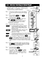
8-4. Calibration Using An External Weight
This function calibrates the balance using an external weight.
Step 1 Connect the AC adapter and warm up the balance for at
least 30 minutes with nothing on the weighing pan.
Press and hold
Step 2 Press and hold the CAL key until Calout is
displayed, then release the key.
Step 3 The balance displays Cal 0 .
If you want to change the calibration weight,
press the SAMPLE key and go to step 4.
If you use the calibration weight value stored in
the balance, go to step 5.
Step 4 Specify the calibration weight value as follows:
SAMPLE key ... To switch the display condition to: "All of the
segments blinking" (calibration weight
selection mode) or "The last two digits
blinking" (value adjustment mode).
RE-ZERO key .. To select the calibration weight or adjust the
value. In the value adjustment mode, -15
digits appear after +15 digits.
PRINT key ...... To store the new weight value. Even if the
AC adapter is removed, the data is
maintained in non-volatile memory.
.........
CAL key
To cancel the operation and return to Cal 0 .
Step 5 Confirm that there is nothing on the pan and press the
PRINT key. The balance measures the zero point.
Do not allow vibration or drafts to affect the balance.
The balance displays the calibration weight value.
Step 6 Place the displayed calibration weight on the pan and
press the PRINT key. The balance measures the
calibration weight. Do not allow vibration or drafts to
affect the balance.
Release
Select
Example:
New weight
10001.2 g
Place weight
Step 7 The balance displays end .
Remove the weight from the pan.
Step 8 If the "GLP output (info)" parameter, of the function
Remove
table, is set to "1" or "2", the balance displays glp and
outputs "Calibration Report" using the RS-232C
GLP output
interface or stores the data in memory. For details on
the calibration report format, refer to "11-2 GLP Report".
Step 9 The balance will automatically return to the weighing mode.
Step 10 Place the calibration weight on the pan and confirm that the value displayed
is within ±2 digits of the specified value. If it is not within the range, check
the ambient conditions such as breeze and vibration also check the
weighing pan. Then, repeat steps 1 to 10.
26
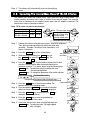
8-5. Calibration Test Using An External Weight
This function tests the weighing accuracy using an external
weight and outputs the result. This is available only when
the "GLP output (info)" parameter is set to "1" or "2".
(Calibration test does not perform calibration)
Press and hold
Step 1 Connect the AC adapter and warm up the balance
for at least 30 minutes with nothing on the weighing
pan.
Release
Step 2 Press and hold the CAL key until CCout is
displayed, then release the key.
Select
Step 3 The balance displays CC 0 .
If you want to change the target weight, press
the SAMPLE key and go to step 4.
A list of usable weights is shown on page 24.
If you use the target weight value stored in
the balance, go to step 5.
Step 4 Specify the target weight value as follows:
SAMPLE key ... To switch the display condition to: "All of the
segments blinking" (target weight selection
mode) or "The last two digits blinking" (value
adjustment mode).
Example:
.
RE-ZERO key To select the target weight or adjust the value.
New weight
10001.2 g
In the value adjustment mode, -15 digits
appear after +15 digits.
PRINT key ...... To store the new weight value. Even if the AC adapter is
removed, the data is maintained in non-volatile memory.
CAL key ......... To cancel the operation and return to CC 0 .
Step 5 Confirm that there is nothing on the pan and press the
PRINT key. The balance measures the zero point and
displays the measured value. Do not allow vibration or drafts
to affect the balance. The balance displays the target weight Place weight
value.
Step 6 Place the displayed target weight on the pan and press
the PRINT key. The balance measures the target
weight and displays the measured value. Do not allow
vibration or drafts to affect the balance.
Step 7 The balance displays end .
Remove the weight from the pan.
glp
Step 8 The balance displays
and outputs
"calibration test report" using the RS-232C
interface or stores the calibration test data in
memory. Refer to "11-2 GLP Report" of the
function table for details.
27
Remove
GLP output
Step 9 The balance will automatically return to the weighing
mode.
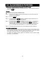
8-6. Correcting The Internal Mass Value Of The GX-K Series
The balance can correct the internal mass value within the range shown below. This
function corrects the internal mass value to conform to an external weight. The corrected
mass value is maintained in non-volatile memory even if the AC adapter is removed. The
internal mass value is corrected as follows:
Note GF-K series can not use this function.
Model
GX-8K GX-8K2
GX-12K GX-20K
GX-30K GX-32K
Target Range
2kg
±0.50g
10kg
±5.0g
10kg
100000 g
The same mass
Correction the internal
mass by +0.3g at 10kg.
Calibrate with the
corrected internal mass.
10kg
100003 g
Corrected external weight
l
Step 1 Calibrate the balance using the internal mass. (one-touch calibration)
Then, place an external weight and confirm the value to be
corrected. Example: The value is to be corrected by +0.3
gram in 10 kilogram.
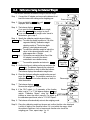
Step 2 Press the ON:OFF key to turn off the display.
Step 3 While pressing and holding the PRINT key and
the SAMPLE key, press the ON:OFF key. The
balance displays p5 .
With these keys Press the key
held down
Step 4 Press the PRINT key. Then the balance displays the function
switches. Set the function table switch and internal mass
correction switch to "1" as shown above using the following keys.
SAMPLE key... To select the switch to change the value.
The selected digit blinks.
..
RE-ZERO key To change the parameter of the switch selected.
Function table switch
Correction switch of internal mass
Step 5 Press the PRINT key to store the new setting. The
balance returns to the weighing mode.
Step 6 Press and hold the SAMPLE key to enter the function
table and release the key when ba5fnc is displayed.
Step 7 Press the SAMPLE key several times until C5 in is
displayed, then release the key.
Step 8 Press the PRINT key to enter the procedure for
correcting the internal mass value.
Step 9 Correct the internal mass value using the following keys.
RE-ZERO key ..To select the value. (-50 digits appear
after +50 digits)
28
Press and hold
PRINT
CAL
key.......To store the new value and display the next
menu item of the function table.
key ..........To cancel the correction and display the next
menu item of the function table.
Step 10 Press the CAL key to return the weighing mode.
Step 11 Press the CAL key to calibrate the balance using the internal mass.
Step 12 Place the external weight on the pan and confirm that the correction has been
performed properly. In this example, confirm that the value displayed is within the
range that is described at "Accuracy after calibration using the internal mass" of "20.
Specification ". If the value is incorrect, repeat the correction.
29
9. Function Switch And Initialization
9-1. Permit Or Inhibit
The balance stores parameters that must not be changed unintentionally (Example:
Calibration data for accurate weighing, Data for adapting to the operating environment,
Control data for the RS-232C interface). There are five switches for the purpose of
protecting parameters. Each switch can select either "permit" or "inhibit". The "inhibit"
protects parameters against unintentional operations.
Step 1 Press the ON:OFF key to turn off the display.
Step 2 While pressing and holding the PRINT key and
the SAMPLE key, press the ON:OFF key to
display p5 .
Step 3 Press the PRINT key. Then the balance displays the function switches.
Step 4 Set the switches using the following keys.
SAMPLE key
To select a switch to change the parameter. The selected switch
blinks.
RE-ZERO key
To change the parameter of the switch selected.
0
To inhibit changes. (Can not be used.)
1
To permit changes. (Can be used.)
PRINT key
To store the new parameter and return to the weighing mode.
CAL key
To cancel the operation and return to the weighing mode.
GX-K series. The display shown left indicates the factory settings.
Function table
0
1
To inhibit changes to the function table.
To permit changes to the function table.
Calibration using the internal mass (One-touch calibration)
0
1
To inhibit calibration using the internal mass.
To permit calibration using the internal mass.
Calibration using an external weight
0
1
To inhibit calibration using an external weight.
To permit calibration using an external weight.
Automatic self calibration (Calibration due to changes in temperature)
0
1
To inhibit automatic self calibration.
To permit automatic self calibration.
Internal mass correction
0
1
To inhibit correction
To permit correction
30
GF-K series. The display shown left indicates the factory settings.
Function table
0
1
To inhibit changes to the function table.
To permit changes to the function table.
Not used
Calibration using an external weight
0
1
To inhibit calibration using an external weight.
To permit calibration using an external weight.
Not used
9-2. Initializing The Balance
This function returns the following parameters to factory settings.
Calibration data
Function table
The sample unit mass value (counting mode),
100% reference mass value (percent mode)
The data that is stored in the balance using the data memory function
External calibration weight and target weight value
Function switch settings
Liquid density and temperature in the density mode
Note Be sure to calibrate the balance after initialization.
Step 1 Press the ON:OFF key to turn off the display.
Step 2 While pressing and holding the PRINT key and
the SAMPLE key, press the ON:OFF key to
display p5 .
Step 3 Press the SAMPLE key to display Clr .
Step 4 Press the PRINT key.
To cancel this operation, press the CAL key.
Step 5 Press the RE-ZERO key to display Clr go .
Step 6 Press the PRINT key to initialize the balance.
The balance will automatically return to the weighing
mode.
31
With these keys Press the key
held down
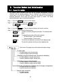
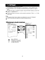
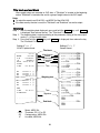
10. Function Table
This function table reads or rewrites the parameters that are stored in the balance. These
parameters are maintained in non-volatile memory, even if the AC adapter is removed.
10-1-1.
Structure And Sequence Of The Function Table
This function table menu consists of two layers. The first layer is the "Class" and the second
layer is the "Item". It has effect that a parameter is stored in each item and is displayed latest.
New parameters are applied to the balance after the PRINT key is pressed.
Example
This example sets "Stores weighing data" for "Data memory" and "1 minute" for "Interval
time".
Weighing mode
Start.
Item
Data memory
Press and hold
Press several
times
Press several
times
Parameter
Stores weighing data
Class
Item
Parameter
1 minute
Press five times
Item
Interval time
Finish
Weighing mode
Caution
Check the settings and condition before changing parameters.
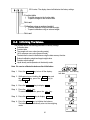
10-1-2.
Display And Operation Keys
The symbol " " shows effective parameter.
When pressed and held in the weighing mode, enters the function table mode.
Selects the class or item in the function table mode.
Changes the parameter.
When a class is displayed, moves to an item in the class.
When an item is displayed, stores the new parameter and displays the next class.
32
When an item is displayed, cancels the new parameter and displays the next class.
When a class is displayed, exits the function table mode and returns to the weighing mode.
33
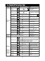
10-2.Details Of The Function Table
Class
Item and Parameter
Cond
Condition
5t-b
Stability band width
Description
0
1
2
0
1
2
0
1
0
1
0
1
0
1
0
1
0
1
0
1
0
1
0
1
Fast response, sensitive value FAST Can be changed by response
MID. adjustment. With "Hold 1", sets the
averaging time.
Slow response, stable value SLOW
The stabilization indicator illuminates
Stable when within ±1 digit
with the display fluctuation within the
range. With "Hold 1", sets the stable
range.
Stable when within ±3 digits
Holds the display when stable in
OFF
animal mode. With "Hold 1", ANIMAL
ON
turns on.
Hold
Hold function
trc
OFF
Keeps zero display by tracking zero
drift.
Zero tracking
ON
5pd
5 times/second
Period to refresh the display
ba5fnc
Display refresh rate
10 times/second
Environment
pnt
Point (.)
Decimal point format
Display
Decimal point
Comma (,)
p-on
OFF
Turns on the weighing mode display
when the AC adapter is connected.
Auto display-ON
ON
poff
OFF
Turns off the display after 10
minutes of inactivity.
Auto display-OFF
ON (10 minutes)
Capacity indicator.
g5i
OFF
Zero:
0%
Capacity indicator
ON
Maximum capacity: 100%
add
OFF
Displays and outputs the total value
of the weighing data.
Accumulation function
ON
Select whether or not to display the
rng
Does not display
smallest displayable weighing value
Display at start
Displays
at weighing start.
Confirms and sets the time and
Cl adj
date. The time and date are added
Refer to "10-7. Clock and Calendar Function"
Clock
to the output data.
0 No comparison
1 Comparison, excluding "near zero" when stable value or overloaded
Cp
2 Comparison, including "near zero" when stable value or overloaded
Comparator mode
3 Continuous comparison, excluding "near zero"
4 Continuous comparison, including "near zero"
Select Cp Hi or Cp lo.
Cp in
0 Set the upper lower limit value
Select Cp ref or Cp lmt.
Data input method
1 Set the reference value
Select whether or not to add the
Cp-r
0 Not added
comparison results to the output
Cp fnc
Comparison results
1 Added
data.
Comparator
Displays the results on the main
Cp-b
0 OFF
portion of the display in place of the
Main display comparison
1 ON
weight value.
bep
0
OFF
Select whether or not to sound the
Displayed
LO buzzer.
LO buzzer
1 ON
only when
Comparator
bep
0 OFF
Select whether or not to sound the
output
OK buzzer.
(GX-04K) is
OK buzzer
1 ON
installed
bep
0 OFF
Select whether or not to sound the
HI buzzer.
HI buzzer
1 ON
: Functions for GX-K series.
: Factory settings. Digit is a unit of minimum weighing value.
34
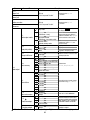
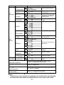
Class
Item and Parameter
Cp Hi
Upper limit
Cp lo
Lower limit
Cp ref
Reference value
Cp lmt
Tolerance
Description
Refer to
"10-8. Comparator Function"
Displayed when Cp in 0
is selected.
Refer to
"10-8. Comparator Function"
Displayed when Cp in 1
is selected.
0 Key mode
prt
Data output mode
1
2
3
ap-p
Auto print polarity
ap-b
Auto print difference
dout
Data output
data
Data memory
int
Interval time
d-no
Data number output
5-td
Time/Date output
5-id
ID number output
: Functions for GX-K series.
Auto print mode A
(Reference = zero)
Auto print mode B
(Reference = last stable value)
Stream mode /
Interval memory mode
Plus only
Minus only
Both
10 digits
100 digits
1000 digits
Not used
Stores unit mass in counting mode
Stores weighing data
Stores calibration data
Stores comparator settings
Stores tare value
Every measurement
2 seconds
5 seconds
10 seconds
30 seconds
1 minute
2 minute
5 minute
10 minute
No output
Output
No output
Time only
Date only
Time and date
No output
Output
Accepts the PRINT key only when
the display is stable.
Outputs data when the display is
stable and conditions of ap-p, ap-b
and the reference value are met.
With data 0, outputs data
continuously; with data 2, uses
interval memory.
Displayed value>Reference
0
Displayed value<Reference
1
Regardless of displayed value
2
0
Difference between reference value
1
and displayed value
2
0
1
2
Related items:
prt int, d-no, 5-td, info
3
4
5
0
1
2
3
Interval time in the interval memory
4
mode when using prt 3 data 2
5
6
7
8
0
Refer to "12. DATA MEMORY"
1
0
Selects whether or not the time
1
or date is added to the weighing
data. Refer to "10-7. Clock and
2
Calendar Function" for details.
3
0
Selects whether or not the ID
number is output.
1
: Factory settings. Digit is a unit of minimum weighing value.
35
Class
dout
Data output
Item and Parameter
pU5e
Data output pause
at-f
Auto feed
info
GLP output
ar-d
Zero after output
bp5
Baud rate
btpr
Data bit, parity bit
5if
Serial
interface
Crlf
Terminator
type
Data format
Description
0
1
0
1
0
1
2
0
1
0
1
2
3
4
5
0
1
2
0
1
0
1
2
3
4
5
0
1
0
1
0
1
0
1
No pause
Pause (1.6 seconds)
Not used
Used
No output
AD-8121 format
General data format
Not used
Used
600 bps
1200 bps
2400 bps
4800 bps
9600 bps
19200 bps
7 bits, even
7 bits, odd
8 bits, none
CR LF
CR
A&D standard format
DP format
KF format
MT format
NU format
CSV format
No limit
1 second
No output
Output
Not used
Used
Water temperature
Liquid density
Selects the data output interval.
Selects whether or not automatic
feed is performed.
Selects GLP output method.
For how to set time and date to be
added, refer to "10-7. Clock and
Calendar Function".
Adjusts zero automatically after data
is output
CR: ASCII code 0Dh
LF: ASCII code 0Ah
Refer to "10-5. Description of Item
"Data Format".
t-Up
Selects the wait time to receive a
command.
Timeout
erCd
AK: ASCII code 06h
AK, Error code
Ct5
Controls CTS and RTS.
CTS, RTS control
d5 fnc
ldin
Available only when density mode is
selected
Density function Liquid density input
mlt
Available only when programmable-unit mode is selected.
Refer to "13. Programmable Units" for details".
Programmable-unit (Multi-unit)
Unit
Refer to "5. Weighing Units".
Unit
C5 in
Displayed only when the internal mass value correction switch is set
to 1. Refer to "8. Calibration".
Internal mass correction
id
Refer to "11. ID Number And GLP Report".
ID number setting
: Functions for GX-K series.
: Factory settings. Digit is a unit of minimum weighing value.
Caution
The balance may not transmit the data completely at the specified refresh rate, depending
on the baud rate or data added to the weighing data such as time, date and ID number.
36
10-3.Description Of The Class "Environment, Display"
Condition ( Cond )
Cond 0
This parameter is for sensitive response to the fluctuation of a weight value. Used
for powder target weighing, weighing a very light sample or when quick response
weighing is required. After setting, the balance displays FAST .
Cond 2
This parameter is for stable weighing with slow response. Used to prevent a
weight value from drifting due to vibration or drafts. After setting, the balance
displays SLOW .
Notes
In automatic response adjustment, the weighing speed is selected
automatically.
With "Hold function (Hold)" set to "ON (1)", this item is used to set the
averaging time.
Stability band width ( 5t-b )
This item controls the width to regard a weight value as a stable value. When the fluctuation
per second is less than the parameter, the balance displays the stabilization indicator and
outputs or stores the data. The parameter influences the "Auto print mode"
5t-b 0 This parameter is used for sensitive response of the stabilization indicator. Used
for exact weighing.
5t-b 2
This parameter ignores slight fluctuation of a weight value. Used to prevent a
weight value from drifting due to vibration or drafts.
Note
With "Hold function (Hold)" set to "ON (1)", this item is used to set the
stabilization range.
Hold function ( Hold ) (Animal weighing mode)
This function is used to weigh a moving object such as an animal. When the weighing data
is over the weighing range from zero and the display fluctuation is within the stabilization
range for a fixed period of averaging time, the processing indicator illuminates and the
balance displays the average weight of the animal. When the animal is removed from the
weighing pan, the display returns to zero automatically. This function is available only when
the hold function parameter is set to "1" (the animal mode indicator ANIMAL illuminates)
and any weighing unit other than the counting mode is selected. The stabilization range and
averaging time are set in "Condition (Cond)" and "Stability band width (5t-b)".
Weighing range
GX-8K
GX-8K2
2g
GF-8K
GF-8K2
GX-12K GX-20K
GX-30K GX-32K
20g
GF-12K
GF-20K
GF-30K
GF-32K
Averaging time
Cond 0 2 sec.
Faster
Cond 1 4 sec.
Cond 2 8 sec. More accurate
37
Stable range
5t-b 0
Small
5t-b 1
5t-b 2
Big
Zero tracking ( trc )
This function tracks zero point drift caused by changes in the environment and stabilizes the
zero point. When the weighing data is only a few digits, turn the function off for accurate
weighing.
trc 0
The tracking function is not used. Used for weighing a very light sample.
trc 1
The tracking function is used. Used for stable zero display.
Display refresh rate ( 5pd )
Period to refresh the display. This parameter influences "Baud rate", "Data output pause"
and "Stream mode".
Note
This item is selected automatically in the weighing speed adjustment.
Decimal point ( pnt )
The decimal point format can be selected.
Auto display-ON ( p-on )
When the AC adapter is plugged in, the display is automatically turned on without the
ON:OFF key operation, to display the weighing mode. Used when the balance is built into
an automated system. 30 minutes warm up is necessary for accurate weighing.
Auto display-OFF ( poff )
When the AC adapter is connected and no operation is performed (inactivity state) for 10
minutes, the display is automatically turned off and the standby indicator illuminates.
Capacity indicator ( g5i )
In the weighing mode, the indicator displays the weighing data relative to the weighing
capacity in percentage. (Zero = 0%, maximum capacity = 100%)
When the "Data memory (data)" parameter is set to "1" (to store unit mass in the counting
mode), "2" (to store the weighing data), "4" (to store comparator settings) or "5" (to store tare
value), the indicator displays the information stored in memory, such as the amount of
memory data or data number.
Accumulation function ( add )
The accumulation function adds the weighing data, displays and outputs the total value.
Refer to "6-5. Accumulation Function." for details.
Display at start ( rng )
When the weighing accuracy is not so strict, the smallest displayable weighing value can be
turned off without any key operation at weighing start. Useful when the balance is built into
an automated system.
38
10-4.Description Of The Item "Data Output Mode"
The parameter setting of "Data output mode (prt)" applies to the performance when the
"Data memory (data)" parameter is set to "2" (to store the weighing data) and when the data
is transmitted using the RS-232C interface.
Key mode
When the PRINT key is pressed with the stabilization indictor turned on, the balance
outputs or stores the weighing data and the display blinks one time.
Required setting
dout
prt 0
Key mode
Auto print modes A and B
When the displayed value is stable and the conditions of "Auto print polarity", "Auto print
difference" and reference value are met, the balance outputs or stores the weighing data.
When the PRINT key is pressed with the stabilization indictor turned on, the balance
outputs or stores the data and the display blinks one time.
Auto print modes A
Example
For weighing each time a sample is placed and removed, with "ar-d"
set to "1" (to adjust zero after the data is output).
Required setting
dout
prt 1
Auto print mode A (reference = zero)
dout
ap-p
Auto print polarity
dout
ap-b
Auto print difference
dout
ar-d 1 Zero after output
Auto print modes B
Example
For weighing while a sample is added.
Required setting
dout
prt 2
Auto print mode B (reference = last stable value)
dout
ap-p
Auto print polarity
dout
ap-b
Auto print difference
Stream mode
The balance outputs the weighing data continuously regardless of the display condition. The
display does not blink in this mode. The interval memory mode is used when the "Data
memory (data)" parameter is set to "2" (to store the weighing data).
Example
For monitoring data on a computer.
Required setting
dout
prt 3
Stream mode
dout
data 0 Data memory function is not used
ba5fnc 5pd
Display refresh rate
5if
bp5
Baud rate
Caution The balance may not transmit the data completely at the specified refresh rate,
depending on the baud rate or data added to the weighing data such as time,
date and ID number.
39
Interval memory mode
The weighing data is periodically stored in memory.
Example
For periodical weighing without a personal computer command and
to output all of the data, to a computer, at one time.
The GX-K series can use time and date with "Time/Date output (5-td)".
Required setting
dout
prt 3
Interval memory mode
dout
data 2 Data memory function is used
dout
int
Interval time
dout
5-td1, 2, or 3
Adds the time and date.
Optional setting
10-5.Description Of The Item "Data Format"
A&D standard format
5if type 0
This format is used when the peripheral equipment can receive the A&D format.
If an AD-8121B is used, set the printer to MODE 1 or 2.
This format consists of fifteen characters excluding the terminator.
A header of two characters indicates the balance condition.
The polarity sign is placed before the data with the leading zeros. If the data is zero, the plus
sign is applied.
The unit, consisting of three characters, follows the data.
Header
Data
Stable header
Unstable header
Overload header
Unit
Terminator
Stable header of counting mode
DP (Dump print) format 5if type 1
This format is used when the peripheral equipment can not receive the A&D format.
If an AD-8121B is used, set the printer to MODE 3.
This format consists of sixteen characters excluding the terminator.
A header of two characters indicates the balance condition. No overload header is used.
The polarity sign is placed before the data, with spaces in place of leading zeros, if the data
is not zero or overloaded.
The unit, consisting of three characters, follows the data.
Header
Data
Stable header
Unstable header
Unit
Terminator
Stable header of counting mode
40
KF format
5if type 2
This is the Karl-Fischer moisture meter format and is used when the peripheral equipment
can only communicate using this format.
This format consists of fourteen characters excluding the terminator.
This format has no header characters.
The polarity sign is placed before the data, with spaces in place of leading zeros, if the data
is not zero or overloaded.
This format outputs the unit only for a stable value.
Data
Unit
Terminator
Stable value
Unstable value
MT format
5if type 3
A header of two characters indicates the balance condition.
The polarity sign is used only for negative data.
The weighing data uses spaces in place of the leading zeros.
The character length of this format changes dependent upon the unit
Header
Data
Unit
Terminator
Stable header
Unstable header
Overload header
NU (numerical) format
5if type 4
This format outputs only numerical data.
This format consists of nine characters excluding the terminator.
The polarity sign is placed before the data with the leading zeros. If the data is zero, the plus
sign is used.
Data
Terminator
CSV format
5if type 5
This format separates the data of A&D standard format and the unit by a comma ( , ).
This format outputs the unit even when the data is overloaded.
When the ID number, data number, time and date are added at "Data output (dout)" of the
function table, outputs ID number, data number, date, time and weighing data in this order
and separates each item by a comma and treats all the items as one group of data.
Note
GF-K series can not append date and time.
ID number Data number
Date
Time
Weighing data
41
10-5-1.
Description of the Data Format Added to the Weighing
Data
ID number
dout 5-id 1
The number to identify a specific balance.
This format consists of seven characters excluding the terminator.
Data number
dout d-no 1
This format outputs the data number just before the data is transmitted using the RS-232C
interface.
This format consists of six characters excluding the terminator.
When CSV format (5if type 5) is selected, the period ( . ) is replaced with a comma ( , ).
Data number
Terminator
Date
dout 5-td 2 or 3
The date output order can be changed in "Clock (Cl adj)".
The year is output in a four-digit format.
Note
GF-K series does not use this format.
Time
dout 5-td 1 or 3
This format outputs time in 24-hour format.
Note
GF-K series does not use this format.
Tare value
When the tare value in memory is recalled, the tare value is output before the weighing data.
Tare value recalled from memory
Net value
Comparison results
By setting "Comparison results (Cp-r)" of the function table to "1", the comparison results
can be added to the data output using the RS-232C serial interface. Use A&D standard
format (type 0).
The comparison results are added after the header in A&D standard format as below.
Header
Data
Unit
Comparison result
When the comparison result is HI
When the comparison result is OK
When the comparison result is LO
Not applicable
Note
42
Terminator
When the data described above is added to the weighing data, the output is in the
following order: ID number, Data number, Date, Time and Weighing data.
10-6.Data Format Examples
Stable
Unstable
Overload
Positive error
Overload
Negative error
Space, ASCII 20h
Carriage Return, ASCII 0Dh
Line Feed, ASCII 0Ah
43
Units
A&D
D.P.
KF
g
kg
Counting mode
Percent mode
Ounce (Avoir)
Pound
Pound Ounce
Troy Ounce
Metric Carat
Momme
Pennyweight
Grain
Tael (HK general, Singapore)
Tael (HK, jewelry)
Tael (Taiwan)
Tael (China)
Tola (India)
Messghal
Density
Multi
Space, ASCII 20h
Note
When "Pound Ounce" is selected, the data is output with the unit of ounce (oz).
The unit Grain is not available for the GX-32K and GF-32K.
44
MT
10-7.Clock And Calendar Function
The GX-K series is equipped with a clock and calendar function. When the "GLP output
(info)" parameter is set to "1" or "2" and the "Time/Date output (5-td)" parameter is set to
"1", "2" or "3", the time and date are added to the output data. Set or confirm the time and
date as follows:
Note
GF-K series does not use this function.
Operation
Step 1 Press and hold the SAMPLE key until ba5fnc of the function table is displayed in
the weighing mode, then release the key.
Step 2 Press the SAMPLE key several times to display Cl adj .
Step 3 Press the PRINT key.
The balance enters the mode to confirm or set the time and date.
Confirming the time
Step 4 The current time is displayed with all the digits blinking.
When the time is correct and the date does not need to be
confirmed, press the CAL key and go to step 8.
When the time is correct and the date is to be confirmed,
press the SAMPLE key and go to step 6.
When the time is not correct and is to be changed, press
the RE-ZERO key and go to step 5.
Setting the time (with part of the digits blinking)
Step 5 Set the time in 24-hour format using the following keys.
SAMPLE key ....To select the digits to change the value.
The selected digits blink.
RE-ZERO key...To increase the value by one.
MODE key .......To decrease the value by one.
PRINT key .......To store the new setting, display end
and go to step 6.
CAL key ..........To cancel the new setting and go to step 6.
Confirming the date
Step 6 The current date is displayed with all the digits blinking.
To change the display order of year (y), month (m) and day (d),
press the MODE key. The date is output in the order as
specified.
When the date is correct and the operation is to be
finished, press the CAL key and go to step 8.
When the time is to be confirmed again, press the SAMPLE
key and go back to step 4.
When the date is not correct and is to be changed, press
the RE-ZERO key and go to step 7.
Note
The year is expressed using a two-digit format.
For example: The year 2004 is expressed as "04".
45
Store
Goes to date
setting mode
Setting the date (with part of the digits blinking)
Step 7 Set the date using the following keys.
SAMPLE key ....To select the digits to change the value.
The selected digits blink.
RE-ZERO key...To increase the value by one.
MODE key .......To decrease the value by one.
PRINT key .......To store the new setting, display end and
go to step 8.
CAL key ..........To cancel the new setting and go to step 8.
Date setting mode
Quitting the operation
Step 8 The balance displays the next menu item of the function
table. Press the CAL key to exit the clock and calendar
function and return to the weighing mode.
Note
Store
Do not enter invalid values such as a non-existing date
when setting the time and date.
When the clock backup battery has been depleted, the
balance displays rtc pf . Under this condition, press
any key and set the time and date. The dead battery
only affects the clock and calendar function. Even so,
the function works normally as long as the AC adapter
is connected to the balance.
10-8.Comparator Function
The results of the comparison are indicated by HI, OK or LO on the display.
Operating conditions:
No comparison
Comparison when the weighing data is stable or overloaded, excluding "near zero"
Comparison when the weighing data is stable or overloaded, including "near zero"
Continuous comparison, excluding "near zero"
Continuous comparison, including "near zero"
To compare, use:
Upper limit value and lower limit value
Reference value and tolerance value
Input method:
Digital input
Weighing input
For a description of "Comparator mode (Cp fnc)", refer to "10-2. Details of the Function
Table".
"near zero" means that weighing value is within ±10 digits from zero point.
Example: In case of GX-20K, the range of ±1.0g is "near zero".
46
10-8-1.
Example 1
Comparison when the weighing data is stable or overloaded, excluding "near zero", upper
limit and lower limit.
Selecting a comparator mode
Step 1 Press and hold the SAMPLE key until ba5fnc of the function table is displayed,
then release the key.
Step 2 Press the SAMPLE key several times to display Cp fnc .
Step 3 Press the PRINT key.
Step 4 Press the RE-ZERO key several times to display Cp 1 .
Step 5 Press the SAMPLE key to display Cp in .
Step 6 Press the RE-ZERO key several times to display Cp in 0 .
Step 7 Press the PRINT key to store the selected mode.
Entering the upper and lower limit values
Step 8 With Cp Hi displayed, press the PRINT key. The current setting of the upper
limit value is displayed with all of the digits blinking.
When the current setting is not to be changed, press the PRINT or CAL key to
go to step 9.
When the current setting is to be changed, press the RE-ZERO key.
The balance is now in the digital input mode. To use the weighing input mode,
press and hold the MODE key.
Digital input mode
Change the setting using the following keys.
SAMPLE key .... To select the digit to change the value.
RE-ZERO key ... To change the value of the digit selected.
MODE key ....... To switch the polarity.
PRINT key ....... To store the new setting and go to step 9.
CAL key .......... To cancel the new setting and go to step 9.
Weighing input mode
Press the RE-ZERO key. The balance displays 00 g . Place a sample, with a mass
that corresponds to the upper limit value, on the pan. Press the PRINT key to
store the upper limit value. Remove the sample. The balance displays Cp lo .
Step 9 With Cp lo displayed, press the PRINT key. The current setting of the lower limit
value is displayed with all of the digits blinking.
When the current setting is not to be changed, press the PRINT or CAL key to go
to step 10.
When the current setting is to be changed, press the RE-ZERO key.
The balance is now in the digital input mode. To use the weighing input mode, press
and hold the MODE key.
Enter the lower limit value in the same way as described in step 8. Then, go to step
10.
47
Step 10 Press the CAL key to exit the comparator function and return to the weighing mode.
48
10-8-2.
Example 2
Continuous comparison, including "near zero", reference value and tolerance value.
Selecting a comparator mode
Step 1 Press and hold the SAMPLE key until ba5fnc of the function table is displayed,
then release the key.
Step 2 Press the SAMPLE key several times to display Cp fnc .
Step 3 Press the PRINT key.
Step 4 Press the RE-ZERO key several times to display Cp 4 .
Step 5 Press the SAMPLE key to display Cp in .
Step 6 Press the RE-ZERO key several times to display Cp in 1 .
Step 7 Press the PRINT key to store the selected mode.
Entering the reference and tolerance values
Step 8 With Cp ref displayed, press the PRINT key. The current setting of the reference
value is displayed with all the digits blinking.
When the current setting is not to be changed, press the PRINT or CAL key to go
to step 9.
When the current setting is to be changed, press the RE-ZERO key.
The balance is now in the digital input mode. To use the weighing input mode, press
and hold the MODE key.
Digital input mode
Change the setting using the following keys.
SAMPLE key .... To select the digit to change the value.
RE-ZERO key ... To change the value of the digit selected.
MODE key ....... To switch the polarity.
PRINT key ....... To store the new setting and go to step 9.
CAL key .......... To cancel the new setting and go to step 9.
Weighing input mode
Press the RE-ZERO key. The balance displays 00 g . Place a sample , with a
mass that corresponds to the reference value, on the pan. Press the PRINT key
to store the reference value. Remove the sample. The balance displays Cp lmt .
Step 9 With Cp lmt displayed, press the PRINT key. The current setting of the tolerance
value is displayed with all the digits blinking.
When the current setting is not to be changed, press the PRINT or CAL key to go
to step 10.
When the current setting is to be changed, press the RE-ZERO key.
The balance is now in the digital input mode. Change the setting using the following keys.
SAMPLE key .... To select the digit to change the value.
RE-ZERO key ... To change the value of the digit selected.
PRINT key ....... To store the new setting and go to step 10.
CAL key .......... To cancel the new setting and go to step 10.
49
Note Enter the tolerance value in percentage, with the reference value as 100%.
Only the digital input mode is available for setting the tolerance value.
The MODE key is not used to set the tolerance value.
Step 10 Press the CAL key to exit the comparator function and return to the weighing mode.
Note When Pound/Ounce is selected as a weighing unit, enter the values in ounces
for comparison.
In the density mode, comparison is performed to the density obtained.
50
10-8-3.
Adding the Comparison Results
By setting the "Comparison results (Cp-r)" of the function table to "1", the comparison results
can be added to the data output using the RS-232C serial interface. Use A&D standard
format (type 0). The AD-8121B printer can not be used.
The comparison results are added after the header in A&D standard format as below.
Header
10-8-4.
Data
Unit
Comparison result
When the comparison result is HI
When the comparison result is OK
When the comparison result is LO
Not applicable
Terminator
Main Display Comparison Function
The main display comparison function displays the comparison results in a magnified way,
on the main portion of the display in place of the weight value.
Selecting a unit
Step 1 Press the MODE key to select a unit to be used for comparison.
Note While the main display comparison function is in use, unit selection using
the MODE key is not available.
Setting the function table
Step 2 Press and hold the SAMPLE key until ba5fnc of the function table is displayed,
then release the key.
Step 3 Press the SAMPLE key several times to display Cp fnc .
Step 4 Press the PRINT key.
Step 5 Press the SAMPLE key several times to display Cp-b 0
Step 6 Press the RE-ZERO key to display Cp-b 1 .
Note To disable the main display comparison function, set the "Main display
comparison (Cp-b)" parameter to "0".
Step 7 Press the PRINT key to store the setting.
Step 8 Press the CAL key to return to the weighing mode.
Setting the comparator values
Setting the comparator values as described in the previous section.
This example uses Cp 3 (Continuous comparison, excluding "near zero").
Using the main display comparison function
Step 1 Press the RE-ZERO key to set the display to zero.
Step 2 Place a sample on the pan. The balance performs a comparison using the specified
comparison values and displays the comparison results, HI, OK or LO.
51
Step 3 Each time the MODE key is pressed, the balance switches between the standard
display and the main display comparison. Note that "go" appears for OK.
Notes
While the main display comparison function is in use, the processing
indicator
illuminates as shown in the illustration.
If the comparison is not performed, for example, because the weight value
is near zero or unstable, the balance displays the weight value even when
the main display comparison function is used.
Even while the main display comparison function is in use, the balance
re-zeroing and data output are possible.
Only the unit selected before this function can be used.
While the main display comparison function is in use, the data memory
function is not available.
To disable the main display comparison function, set the "Main display
comparison (Cp-b)" parameter to "0".
Weighing data and
Comparison results
(Standard display)
Main display
comparison
(The processing indicator illuminates)
Each press alternates the display
Processing indicator
Example: a sample of 1 kg is placed.
Example: a sample of 2 kg is placed.
Example: a sample of 3 kg is placed.
Compares using the specified comparison values.
52
11. ID Number And GLP Report
The ID number is used to identify the balance when Good Laboratory Practice (GLP) is used.
The ID number is maintained in non-volatile memory even if the AC adapter is removed.
The GLP output format is selected at "GLP output (info)" of the function table and can be
output to a personal computer or printer using the RS-232C serial interface.
The GLP output format includes the balance manufacturer, model, serial number, ID
number, date, time and space for signature for weighing data, the weight used and results
for calibration or calibration test data.
The balance can output the following reports for GLP.
"Calibration report" of the calibration, using the internal mass (Calibration due to changes
in temperature and one-touch calibration.)
"Calibration report" of the calibration, using an external weight.
"Calibration test report" of the calibration test, using an external weight.
"Title block" and "End block" for the weighing data.
Calibration and calibration test data can be stored in memory to output several reports at the
same time. Refer to "12. Data Memory" for details.
For details on confirming and setting the time and date for the GX-K series. Refer to "10-7.
Clock and Calendar Function".
Caution
GF-K series does not store the calibration report in memory.
GF-K series does not use the time and date function. Use the calendar function
of AD-8121B printer.
11-1.Setting The ID Number
Step 1 Press and hold the SAMPLE key until ba5fnc of the function table is displayed,
then release the key.
Step 2 Press the SAMPLE key several times to display
id
.
Step 3 Press the PRINT key. Set the ID number using the following keys.
RE-ZERO key ..... To set the character of the digit selected.
Refer to the display character set shown below.
SAMPLE key ...... To select the digit to change the value.
PRINT key ......... To store the new ID number and display ba5fnc .
CAL key ............ To cancel the new ID number and display ba5fnc .
Step 4 With ba5fnc displayed, press the CAL key to return to the weighing mode.
Display character set
53
11-2.GLP Report
Set the following parameters to output the report.
To print the report, set the "GLP output (info)" parameter to "1" and use MODE 3 of the
AD-8121B. Refer to "16-2. Connection to the AD-8121B Printer" for details on using the
printer.
To output the report to a personal computer using the RS-232C interface, set the "GLP
output (info)" parameter to "2".
If the time and date are not correct, set the correct time and date in "Clock (Cl adj)" of the
function table.
Notes
For operational details about calibration and calibration test, refer to "8. Calibration".
The GF-K series does not output time and date to the general format.
Calibration report using the internal mass
Setting of "info 1"
AD-8121 printer format
===========A=&=D
MODEL=====GX-30K
S/N=====01234567
ID=======ABCDEFG
DATE
======2004/12/31
TIME
========12:34:56
CALIBRATED(INT.)
SIGNATURE
Manufacturer
Model
Serial number
ID number
Date
Time
Calibration type
Signature
- - - - - - - -
Setting of "info 2"
General format
~~~~~~~~~~~A~&~D<TERM>
MODEL~~~~~GX-30K<TERM>
S/N~~~~~01234567<TERM>
ID~~~~~~~ABCDEFG<TERM>
DATE<TERM>
~~~~~~2004/12/31<TERM>
TIME<TERM>
~~~~~~~~12:34:56<TERM>
CALIBRATED(INT.)<TERM>
SIGNATURE<TERM>
<TERM>
<TERM>
----------------<TERM>
<TERM>
<TERM>
<TERM>
CR
LF
Space, ASCII 20h
Terminator, CR , LF or CR
Carriage return, ASCII 0Dh
Line feed, ASCII 0Ah
54
Calibration report using an external weight
Setting of "info 1"
AD-8121 printer format
-----------A-&-D
MODEL-----GX-30K
S/N-----01234567
ID-------ABCDEFG
DATE--2004/12/31
TIME----12:34:56
CALIBRATED(EXT.)
CAL.WEIGHT
-----+20000.0--g
SIGNATURE
Setting of "info 2"
General format
~~~~~~~~~~~A~&~D<TERM>
MODEL~~~~~GX-30K<TERM>
S/N~~~~~01234567<TERM>
ID~~~~~~~ABCDEFG<TERM>
DATE<TERM>
~~~~~~2004/12/31<TERM>
TIME<TERM>
~~~~~~~~12:34:56<TERM>
CALIBRATED(EXT.)<TERM>
CAL.WEIGHT<TERM>
~~~~~+20000.0~~g<TERM>
SIGNATURE<TERM>
Manufacturer
Model
Serial number
ID number
Date
Time
Calibration type
Calibration weight
Signature
<TERM>
<TERM>
---------------
---------------- <TERM>
<TERM>
CR
LF
<TERM>
<TERM>
Space, ASCII 20h
Terminator, CR , LF or CR
Carriage return, ASCII 0Dh
Line feed, ASCII 0Ah
Calibration test report using an external weight
Note Calibration test does not perform calibration.
Setting of "info 1"
AD-8121 printer format
-----------A-&-D
MODEL-----GX-30K
S/N-----01234567
ID-------ABCDEFG
DATE--2004/12/31
TIME----12:34:56
CAL.TEST(EXT.)
ACTUAL
----------0.0--g
-----+19999.9--g
TARGET
-----+20000.0--g
SIGNATURE
Setting of "info 2"
General format
Manufacturer
Model
Serial number
ID number
Date
Time
Calibration test type
Zero point value
Target weight value
Target weight
Signature
~~~~~~~~~~~A~&~D<TERM>
MODEL~~~~~GX-30K<TERM>
S/N~~~~~01234567<TERM>
ID~~~~~~~ABCDEFG<TERM>
DATE<TERM>
~~~~~~2004/12/31<TERM>
TIME<TERM>
~~~~~~~~12:34:56<TERM>
CAL.TEST(EXT.)<TERM>
ACTUAL<TERM>
~~~~~~~~~~0.0~~g<TERM>
~~~~~+19999.9~~g<TERM>
TARGET<TERM>
~~~~~+20000.0~~g<TERM>
SIGNATURE<TERM>
<TERM>
<TERM>
---------------
----------------<TERM>
<TERM>
CR
LF
<TERM>
<TERM>
Space, ASCII 20h
Terminator, CR , LF or CR
Carriage return, ASCII 0Dh
Line feed, ASCII 0Ah
55
Title block and end block
When weight values are recorded as GLP data, a "Title block" is inserted at the beginning
and an "End block" is inserted at the end of a group of weight values in the GLP report.
Notes
To output the report to an AD-8121B , use MODE 3 of the AD-8121B.
If the data memory function is used, the "Title block" and "End block" can not be output.
Operation
Step 1 With the weighing data displayed, press and hold the PRINT key, until 5tart
is displayed, then release the key. The "Title block" is output.
Step 2 The weighing data is output according to the parameter setting of the data output
mode (prt) of the function table.
Step 3 Press and hold the PRINT key until recend is displayed, then release the key.
The "End block" is output.
Setting of "info 1"
AD-8121 printer format
Setting of "info 2"
General format
Title block
-----------A-&-D
MODEL-----GX-30K
S/N-----01234567
ID-------ABCDEFG
DATE--2004/12/31
START
TIME----09:30:00
WT---+12345.6--g
WT---+12346.1--g
WT---+12346.2--g
WT---+12346.3--g
WT---+12345.1--g
WT---+12345.3--g
WT---+12347.1--g
WT---+12346.4--g
END
TIME----10:40:15
SIGNATURE
Manufacturer
Model
Serial number
ID number
Date
Time
<TERM>
Weighing data
WT~~~+12345.6~~g<TERM>
WT~~~+12346.1~~g<TERM>
WT~~~+12346.2~~g<TERM>
WT~~~+12346.3~~g<TERM>
WT~~~+12345.1~~g<TERM>
WT~~~+12345.3~~g<TERM>
WT~~~+12347.1~~g<TERM>
WT~~~+12346.4~~g<TERM>
<TERM>
Time
Signature
END<TERM>
TIME<TERM>
~~~~~~~~10:40:15<TERM>
SIGNATURE<TERM>
<TERM>
<TERM>
---------------
End block
<TERM>
CR
LF
~~~~~~~~~~~A~&~D<TERM>
MODEL~~~~~GX-30K<TERM>
S/N~~~~~01234567<TERM>
ID~~~~~~~ABCDEFG<TERM>
DATE<TERM>
~~~~~~2004/12/31<TERM>
START<TERM>
TIME<TERM>
~~~~~~~~09:30:00<TERM>
Space, ASCII 20h
Terminator, CR , LF or CR
Carriage return, ASCII 0Dh
Line feed, ASCII 0Ah
56
----------------<TERM>
<TERM>
<TERM>
12. Data Memory
Data memory is a function to store weighing data, calibration data and unit mass in memory.
Of the data in memory, the balance can only display the weighing data. The weighing data
and calibration data in memory are available for outputting at one time to a printer or
personal computer. One of the following data sets can be stored:
Excluding date and time
Including date and time
Calibration result of Internal and external calibration
and calibration test
Unit mass in the counting mode
Upper and lower limit values of comparator function
Tare value
Weighing data
GX-K series
Up to 200 sets
Up to 100 sets
GF-K series
Up to 40 sets
-
Last 50 sets
-
Up to 50 sets
Up to 20 sets
Up to 20 sets
Up to 20 sets
Note GF-K series does not output time and date.
12-1.Notes on Using Data Memory
To use the memory function, set the "Data memory (data)" parameter of the function table.
In addition, for weighing data, set the "Time/Date output (5-td)" parameter. For details on
setting the data memory, refer to "10-2. The Function Table".
For weighing data of the GX-K series, the data contents to be stored and the storage
capacity depend on the "Time/Date output (5-td)" parameter setting.
Releasing "Clr"
Upper left of
If a different type of data exists in memory when the data is
the display
stored, "Clr" blinks the upper left of the display. For example,
you want to store weighing data but calibration data or unit mass
data remains in memory.
Under such a condition, before storing data, delete the data in memory as follows:
Step 1 Press and hold the PRINT key until SClr "n"o with "no" blinking is displayed,
then release the key.
Step 2 Press the RE-ZERO key to display SClr "g"o with "go" blinking.
The type of data stored in memory appears in the upper left of the display as
shown below:
PpC
-dd-t
Hi5
Cp
tr
Unit mass in the counting mode
Weighing data without time and date
Weighing data with time and date
Calibration result
parameters of comparator
Tare value
Step 3 Press the PRINT key to delete all the data in memory.
Step 4 The balance displays end and returns to the weighing mode.
57
12-2.Data Memory for Weighing Data
The GX-K series can store 200 sets of weighing data in memory (if time and date are added,
the GX-K series can store 100 sets). Even if the AC adapter is removed, the data is
maintained in non-volatile memory.
The GF-K series can store 40 sets of weighing data in memory. Even if the AC adapter is
removed, the data is maintained in non-volatile memory. The GF-K series does not store
time and date.
It is not necessary that the printer or personal computer be continually connected to the
balance, because the balance stores the weighing data in memory.
The data in memory is available to be displayed on the balance for confirmation, or to output
several sets of data at one time to a printer or personal computer. In the function setting,
what data is to be added to the output data (ID number, data number, time and date) can be
selected.
Storing the weighing data
Note
If "Clr" blinks in the upper left of the display, delete the data in memory.
Step 1 Set the "Data memory (data)" parameter to "2".
Step 2 Set the "Time/Date output (5-td)" parameter as necessary.
Step 3 The storing mode depends on the "Data output mode (prt)" parameter setting.
Four types of storing modes are available to store data.
Key mode .........................When the PRINT key is pressed and the displayed value is
stable, the balance stores the weighing data.
..........
Auto print modes A
When the displayed value is stable and the conditions of "Auto
print polarity", "Auto print difference" and zero point (reference
value) are met, the balance stores the weighing data.
..........
Auto print modes B
When the displayed value is stable and the conditions of "Auto
print polarity", "Auto print difference" and last stable data
(reference value) are met, the balance stores the weighing data.
Interval memory mode.....Weighing data is stored at an interval specified in "Interval time
(int)". Press the PRINT key to start and stop this mode.
The data amount
in memory
Memory full
Weighing data
being displayed
Data number of the
data currently
displayed
Interval memory
standby indicator
Interval memory
active indicator
Memory data
being displayed
Caution
When weighing data is being stored in memory, the data can not be output to a personal
computer using the RS-232C interface.
58
"fUl" indicates that memory is full or the memory capacity has been reached. More data can
not be stored unless the memory data is deleted.
Automatic self calibration can not be used while the interval memory mode is active.
The following commands can not be used during data storage.
Q
Query command for weighing data.
S
Query command for stable weighing data.
SI
Query command for weighing data.
SIR Query command for continuous weighing data.
Setting the function table
Parameter settings for each output mode are as follows:
Item
Data output Auto print polarity, Data memory
Interval time
Mode
mode
difference
function
prt 0
data 2
Key mode
Not used
Not used
ap-a 0-2
prt 1
data 2
Auto print mode A
ap-b 0-2
prt 2
data 2
Auto print mode B
prt 3
data 2
int 0-8
Interval memory mode
Not used
Set each item for GX-K series, depending on the situation, as follows:
d-no 0
5-td
No
No
Data number
d-no 1
5-td
Yes
Time only
Time and date
5-id 0
5-td
No
Date only
ID number
5-id 1
5-td
Yes
Both
When 5-td 1, 2 or 3 is selected, the amount of data to be stored is 100 sets.
0
1
2
3
Set each item for GF-K series, depending on the situation, as follows:
d-no 0
No
Data number
d-no 1
Yes
5-id 0
No
ID number
5-id 1
Yes
GF-K series does not use time and date.
Enabling the data memory function
Step 1 Press and hold the SAMPLE key until ba5fnc is displayed, then release the key.
Step 2 Press the SAMPLE key several times to display dout .
Step 3 Press the PRINT key.
Step 4 Press the SAMPLE key three times to display data 0 .
Step 5 Press the RE-ZERO key to display data 2 .
Step 6 Press the PRINT key to store the setting.
Step 7 Press the CAL key to return to the weighing mode.
59
Recalling the memory data
Indicators
Confirm that the "Data memory (data)" parameter is set to "2".
Step 1 Press and hold the PRINT key until reCall is displayed,
then release the key.
Step 2 Press the PRINT key to enter the memory recall mode. The
type of data appears in the upper left of the display as shown to
the right. Recall the data in memory using the following keys.
RE-ZERO key...To proceed to the next data set.
Weighing data
without time and date
Weighing data with
time and date
key .......To go back to the previous data set.
PRINT key .......To transmit the current data using the RS-232C interface.
MODE
With SAMPLE held down, press the CAL key
To delete the current data.
Note Deleting the data will not increase the number of data that can be stored.
CAL key ..........To exit the memory recall mode.
Step 3 Press the CAL key to return to the weighing mode.
Transmitting all memory data at one time
Confirm that the "Serial interface (5if)" parameters are set properly.
Refer to "10. Function Table" and "16-2. Connection To Peripheral
Equipment".
Step 1 Press and hold the PRINT key until reCall is displayed,
then release the key.
Indicators
Weighing data
without time and date
Step 2 Press the SAMPLE key to display out .
Step 3 Press the PRINT key to display out "n"o with "no" blinking.
Step 5 Press the RE-ZERO key to display out "g"o with "go" blinking.
Weighing data with
time and date
Step 6 Press the PRINT key to transmit all data using the RS-232C interface.
Step 7 The balance displays Clear when all data is transmitted.
Press the CAL key to return to the weighing mode.
Deleting all memory data at one time
Step 1 Press and hold the PRINT key until reCall is displayed, then release the key.
Step 2 Press the SAMPLE key several times to display Clear .
Step 3 Press the PRINT key to display Clr "n"o with "no" blinking.
Step 4 Press the RE-ZERO key to display Clr "g"o with "go" blinking.
Step 5 Press the PRINT key to delete all data
Step 6 The balance displays end when all data is deleted.
The balance displays reCall .
Step 7 Press the CAL key to return to the weighing mode.
60
12-3.Data Memory for Calibration and Calibration Test
Calibration data (when and how it is performed) and calibration test
data can be stored in memory.
All the data in memory is available to be output at one time to a
printer or personal computer.
Up to 50 data sets of the latest calibration or calibration test can be
stored. When the memory capacity has been reached, "fUl"
illuminates in the upper left of the display as shown at the right.
Indicator
Storing the calibration and calibration test data
Note If "Clr" appears blinking in the upper left of the display, delete the data in memory.
Store the calibration and calibration test data as follows:
Step 1 Set the "Data memory (data)" parameter to "3".
Step 2 Set the "GLP output (info)" parameter to "1" or "2".
Step 3 With the settings above, each time calibration or calibration test is performed, the
data is stored automatically.
Transmitting the memory data
Note
Confirm that the "Serial interface (5if)" parameters are set properly.
Refer to "10. Function Table" and "16-2. Connection To Peripheral Equipment".
Confirm that the "Data memory (data)" parameter is set to "3".
In the upper left
of the display
Step 1 Press and hold the PRINT key until out is displayed,
then release the key.
Step 2 Press the PRINT key to display out "n"o with "no" blinking.
Step 3 Press the RE-ZERO key to display out "g"o with "go" blinking.
Step 4 Press the PRINT key to transmit all memory data using the RS-232C interface.
Step 5 The balance displays Clear when all memory data is output. Press the CAL
key to return to the weighing mode.
Deleting data stored in memory
Step 1 Press and hold the PRINT key until out is displayed,
then release the key.
In the upper left
of the display
Step 2 Press the SAMPLE key to display Clear .
Step 3 Press the PRINT key to display Clr "n"o with "no" blinking.
Step 4 Press the RE-ZERO key to display Clr "g"o with "go" blinking.
Step 5 Press the PRINT key to delete all data.
Step 6 The balance displays out when all the data has been deleted. Press the CAL
key to return to the weighing mode.
61
12-4.Data Memory for Unit Mass in the Counting Mode
The GX-K series can store 50 data of unit mass for the counting mode.
"p01" is the standard memory of unit mass. Another 49 data of unit mass can be stored.
The GF-K series can store 20 data of unit mass for the counting mode.
"p01" is the standard memory of unit mass. Another 19 data of unit mass can be stored.
Even if the AC adapter is removed, the data is maintained in non-volatile memory.
The unit mass in memory can be recalled and used for weighing.
The unit mass in memory can be recalled and changed.
Note
The recalled unit mass can be changed, using the weighing input mode or the digital input
mode. The weighing input mode uses the specified number of samples to store the unit
mass. The digital input mode enters the unit mass using the keys.
12-4-1.
Storing the unit mass
To store a new unit mass: Recall the stored unit mass to be changed. Then, change the
recalled unit mass using the weighing input mode or the digital input mode, and store the
new unit mass.
GX-K series can store a unit mass from "Pp01" to "p50".
GF-K series can store a unit mass from "Pp01" to "p20".
Step 1 Set the "Data memory (data)" parameter to "1".
Step 2 Press the MODE key to select pcs (counting mode).
If "Clr" appears blinking in the upper left of the display,
delete the data in memory.
Note If the counting mode can not be
No.3. Unit mass number
selected, refer to "5. Weighing Units".
Unit mass data
Step 3 Press and hold the PRINT key until the
balance enters the sample unit mass
confirmation mode. The unit mass last
selected is displayed
Step 4 Select the unit mass number to be used, using the following keys.
RE-ZERO key .. To increase the unit mass
Number of GX-K series: p01 to p50
number by one.
Number of GF-K series: p01 to p20
MODE key ........To decrease the unit mass
by one.
Step 5 To change the selected unit mass:
To use the weighing input mode, press the SAMPLE key to enter the weighing input
mode. Go to "Weighing input mode" on the next page.
To use the digital input mode, press the SAMPLE key, then press and hold the
MODE key to enter the digital input mode. Go to "Digital input mode" on the next
page.
Notes
ACAI can not be performed directly on the recalled unit mass.
62
Using the "UN:mm" command, the unit mass can be recalled.
The unit mass recalled can be output using the "?UW" command.
The unit mass can be changed using the "UW:" command.
"mm" indicates a two-digit numerical value 01 to 50, which corresponds to p01 - p50 of the
GX-K series.
"mm" indicates a two-digit numerical value 01 to 20, which corresponds to p01 - p20 of the
GF-K series.
Weighing input mode
In the weighing input mode, the specified number of samples is placed on the pan to store
the unit mass. Re-storing the unit mass or performing Automatic Counting Accuracy
Improvement (ACAI) on the re-stored unit mass is possible. Follow the procedure described
in "6-2. Counting Mode (PCS)".
Use the following keys to store a unit mass in the weighing input mode.
RE-ZERO key .. To set the display to zero. 10 - pcs ?
10 0 pcs
...
SAMPLE key To change the number of samples to be stored. 10 0 pcs ?
25 0 pcs
.......
PRINT key
Press, after a sample is placed, to store the unit mass. Go to step 3 of the
previous page.
..........
CAL key
To return to the unit mass confirmation mode. Go to step 3 of the
previous page.
.......
MODE key
Press and hold to go to the digital input mode.
Digital input mode
To use this mode, the sample unit mass must be known
beforehand. In the digital input mode, the unit mass value is
entered digitally using the keys. The display in the digital input
mode is shown to the right.
Note ACAI can not be used on the unit mass stored
using the digital input mode.
Value
Decimal point
Digit
Store
Use the following keys to store a unit mass in digital input mode.
SAMPLE key ... To select the digit to be changed.
RE-ZERO key .. To change the value of the selected digit.
MODE key....... To change the decimal point position.
PRINT key....... To store the unit mass. Go to step 3 of the previous page.
CAL key .......... To return to the unit mass confirmation mode. Go to step 3 of the
previous page.
MODE key ....... Press and hold to go to the weighing input mode.
Note If the new unit mass is out of the setting range, "error 2" is displayed.
Refer to "20. Specifications" for the minimum unit mass.
63
12-4-2.
Recalling the unit mass
Step 1 Follow steps1 through 3 in "12-4-1. Storing the unit mass" on the previous page,
to enter the sample unit mass confirmation mode.
+1
No4. of unit
Step 2 Select the unit mass number using the following keys.
mass
GX-K series: p01 to p50,
GF-K series: p01 to p20.
RE-ZERO key ..... To increase the unit mass
number by one.
..........
MODE key
To decrease the unit mass
Output
by one.
-1
Step 3 Press the PRINT key to confirm the selection and
Counting mode
to return to the weighing mode.
To cancel the selection and return to the weighing
mode, press the CAL key.
64
12-5.Data Memory for Comparator Settings
The data memory function can store 20 sets of upper and lower limit values for the
comparator mode. The reference value or tolerance value for the comparator mode can not
be stored in memory.
The upper and lower limit values in memory can be recalled easily using the MODE key
and used for weighing.
The upper and lower limit values in memory can be recalled and changed.
Note
The recalled upper and lower limit values can be changed, using the digital input
mode or the weighing input mode. The digital input mode enters the upper and lower
limit values using the keys. The weighing input mode uses a sample to store the
upper and lower limit values.
12-5-1.
Storing the upper and lower limit values
To store new upper and lower limit values: Recall the stored upper and lower limit values to
be changed ("C01" to "C20") . Then, change the recalled upper and lower limit values using
the digital input mode or the weighing input mode, and store the new value.
Note
While the data memory function is in use, unit selection using the MODE key is
not available.
If "Clr" appears blinking in the upper left of the display, delete the data in memory.
Refer to "12-1. Notes on Using Data Memory".
Step 1 Press the MODE key to select a unit to be
used for storage.
No.3. Comparator number
Upper limit value
Step 2 Set the "Data memory (data)" parameter to "4".
Step 3 Press and hold the PRINT key until the
balance enters the upper and lower limit
values confirmation mode. The upper limit
value last selected is displayed.
Step 4 Select the comparator number to be used, using the following keys.
RE-ZERO key ..... To increase the comparator number by one.
MODE key ......... To decrease the comparator number by one.
Each time the RE-ZERO key or MODE key is pressed, the displayed value
changes as follows: ? C03 HI ? C03 LO ? C04 HI ? C04 LO ?
Step 5 To change the selected upper and lower limit values:
To use the digital input mode, press the SAMPLE key to enter the digital input mode.
Go to "Digital input mode" on the next page.
To use the weighing input mode, press the SAMPLE key, then press and hold the
MODE key to enter the weighing input mode. Go to "Weighing input mode" on the
next page.
65
Notes
Using the "CN:mm" command, the comparator limit values can be recalled.
The upper limit value recalled can be output using the "?HI" command.
The lower limit value recalled can be output using the "?LO" command.
The upper limit value can be changed using the "HI:" command.
The lower limit value can be changed using the "LO:" command.
"mm" indicates a two-digit numerical value 01 to 20, which corresponds to C01 - C20.
Digital input mode
Value
In the digital input mode, the upper and lower limit values are
entered digitally using the keys. Use the following keys to store
upper and lower limit values in digital input mode.
SAMPLE key ... To select the digit to be changed.
RE-ZERO key .. To change the value of the selected digit.
MODE key....... To switch the polarity.
Polarity
PRINT key....... To store the upper and lower limit values.
Go to step 3 of the previous page.
C03
..........
CAL key
To return to the upper and lower limit
values confirmation mode
Go to step 3 of the previous page.
MODE key
Press and hold to go to the weighing input mode.
Digit
Store
Weighing input mode
In the weighing input mode, a sample is placed on the pan to store the upper and lower limit
values.
Notes
Pressing the CAL key will interrupt the operation and the
balance will return to the upper and lower limit values
confirmation mode (step 3 in "Storing the upper and lower
limit values").
To go to the digital input mode, press and hold the MODE key.
Step 1 The first display in the weighing input mode depends on the
comparator number selected in step 4 in "Storing the upper and
lower limit values".
For example, when "C03 H1 " is selected in step 4, the display is
the current weight value and the comparator number with HI
blinking.
Step 2 Place a container on the weighing pan, if necessary.
Press the RE-ZERO key to set the display to zero.
Step 3 Place a sample corresponding to the upper limit value,
on the pan or in the container.
Step 4 Press the PRINT key to store the upper limit value.
66