1
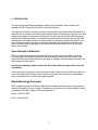
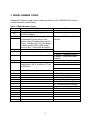
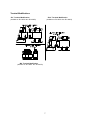
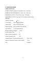
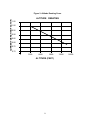
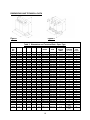
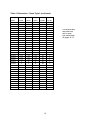
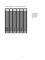
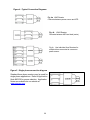
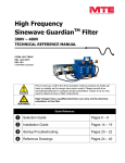
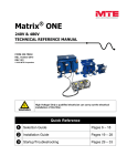
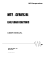
MTE Corporation
MTE - SERIES RL
LINE/LOAD REACTORS
USER MANUAL
PART NO. INSTR – 011
REL. 021126
© 2002 MTE Corporation
IMPORTANT USER INFORMATION
NOTICE
MTE Series RL Line/Load Reactors are components designed to improve the
reliability of adjustable frequency drives, DC drives and a wide variety of other
types of power electronic equipment. In addition they provide input line current
harmonic mitigation and long lead protection for inverter fed motors. MTE
reactors are available in a large number of current ratings and a variety of
inductance values. The suitability of a line/load reactor for a specific application
must therefore be ultimately determined by the customer. In no event will MTE
Corporation assume responsibility or liability for any direct or consequential
damages resulting from the use or application of reactors. Nor will MTE
Corporation assume patent liability with respect to the use of information, circuits
or equipment described in this instruction manual.
2
TABLE OF CONTENTS
1. Safety ...................................................................................................................... 4
2. Introduction ............................................................................................................. 5
3. Model Number Codes............................................................................................ 6
4. Specifications ......................................................................................................... 8
Altitude Derating Curve ....................................................................................... 9
Dimensions and Technical Data ....................................................................... 10
Open Type ……………………………………………………………… 10
Nema Type 1 …………………………………………………………… 13
5. Installation Instructions ....................................................................................... 17
Power Wiring Connection .................................................................................. 18
Grounding .............................................................................................................. 19
Typical Interconnection Diagrams ..................................................................... 20
6. Startup…………………………………………………………………………… 21
3
1. IMPORTANT SAFETY INFORMATION
WARNING
ONLY A QUALIFIED ELECTRICIAN CAN CARRY OUT THE ELECTRICAL
INSTALLATION OF LINE/LOAD REACTORS
WARNING
High voltage is used in the operation of line/load reactors. Use Extreme caution to avoid
contact with high voltage when operating, installing or repairing equipment containing
line/load reactors. INJURY OR DEATH MAY RESULT IF SAFETY PRECAUTIONS
ARE NOT OBSERVED.
Line/load reactors are used in conjunction with inverters, or other electrical equipment
that may feedback lethal voltages. Follow the safety instructions in the equipment used
with the reactor in addition to the safety instruction in this manual.
WARNING
The opening of the branch circuit protective device may be an indication that a fault current has
been interrupted. To reduce the risk of fire or electrical shock, line/load reactors should be
examined and replaced if damaged.
WARNING
An upstream disconnect/protection device must be used as required by the National Electrical
Code (NEC).
WARNING
Even if the upstream disconnect/protection device is open, a drive or inverter down stream of
the line/load reactor may feed back high voltage to the reactor. The inverter or drive safety
instructions must be followed. INJURY OR DEATH MAY RESULT IF THE DRIVE
SAFETY PRECAUTIONS ARE NOT OBSERVED.
WARNING
The frame of line/load reactors must be grounded at least at one of the reactor’s mounting
holes.
WARNING
Only spare parts obtained from MTE Corporation or an authorized MTE distributor can be used.
4
2. INTRODUCTION
This manual was specifically developed to assist in the installation, interconnection and
operation of MTE Corporation Series RL Line/Load Reactors
This manual is intended for use by personnel experienced in the operation and maintenance of
electronic drives, inverters and similar types of power electronic equipment. Because of the high
voltages required by the equipment connected to line/load reactors and the potential dangers
presented by rotating machinery, it is essential that all personnel involved in the operation and
maintenance of line/load reactors know and practice the necessary safety precautions for this
type of equipment. Personnel should read and understand the instructions contained in this
manual before installing, operating or servicing line/load reactors and the drive to which the
reactor is connected.
Upon Receipt of a Reactor:
MTE Line/load Reactors have been subjected to demanding factory tests before shipment.
Carefully inspect the shipping container for damage that may have occurred in transit. Then
unpack the filter and carefully inspect for any signs of damage. Save the shipping container for
future transport of the reactor.
In the event of damage, please contact and file a claim with the freight carrier involved
immediately.
If the equipment is not going to be put into service upon receipt, cover and store the reactor in a
clean, dry location. After storage, ensure that the equipment is dry and that no condensation
has accumulated on the reactor before applying power.
Repair/Exchange Procedure
MTE Corporation requires a Returned Material Authorization Number before it can accept any
reactors that qualify for return or repair. If problems or questions arise during installation, setup,
or operation of the filter, please call us for assistance at:
Phone: 1-262-253-8200
FAX: 1-262-253-8222
5
3. MODEL NUMBER CODES
Standard RL Reactor model number codes are of the form RL-ABCDEF(GHI) with the
number coded as outlined below.
Table 1 Model Number Codes
Character
Description
RLA,B,C,D
Code
Always for Harmonic Compensated
Line/Load Reactor
Characters A, B, C,(D), designate the
Fundamental Current rating of the
Reactor using 2 leading zeros (up to 8
Amps), 1 leading zero (12 to 80 Amps),
no leading zeros (100 to 950 Amps),
and 4-th digit (1,000 Amps and higher)
E
Indicates mechanical configuration
F
Designates the inductance, and
consequently, the % Impedance, Class
at 480 Volts
G,H,I
Modifications
Example: 080XX is an 80 Amp
Reactor
0 Open
1 NEMA-1, Standard Cabinet
2 NEMA-1, Next Size Larger
Cabinet
A Omit Center coil
B_Terminal_Modifications
D Sub. Black Paint for Blue
D1 Conformal Epoxy Coating
T_Temperature_Switches
6
Terminal Modifications
“B1” Terminal Modification
(available on RL-05501 thru RL-40003)
“B14” Terminal Modification
(Available on RL-05501 thru RL-40003)
“B8” Terminal Modification
(Available on RL-00201 thru RL-04503)
7
4. SPECIFICATIONS
AGENCY APPROVALS:
UL-508, File E180243 Component Recognized (1 amp – 2400 amps)
UL-508, File E180243 UL Listed Nema 1 units (1 amp – 2400 amps)
CSA C22.2, File LR29753-13 CSA Certified (1 amp – 1200 amps)
Class H, 200 C, File E66214, Type 180-36, UL Recognized Insulation System
CE Marked
Inductance Tolerance:
+ 10 %
Current Rating:
Refer to product nameplate
Voltage Rating:
Refer to product nameplate
Dielectric Strength:
4000 Volts RMS, 5600 Volts Peak
dv/dt Protection:
17,825 volts/microsecond
Maximum Switching Frequency:
20 KHz
Insulation System Class:
H
Maximum Ambient temperature:
45C
Average Temperature Rise:
115C
Altitude (See figure 3 for altitude derating curve):
Maximum Fundamental Frequency without derating:
Color:
3300 Ft. Max.
60 Hz
Royal Blue
8
Figure 3. Altitude Derating Curve
CURRENT DERATING FACTOR
ALTITUDE DERATING
1.05
1.00
0.95
0.90
0.85
0.80
0.75
0.70
0
3300
6600
9900
ALTITUDE (FEET)
9
13200
16500
DIMENSIONS AND TECHNICAL DATA
Figure 1
Figure 2
Table 3 Dimensions and Technical Data – Open Type
CAT.
NO.
A
B
C
D
E
MTG.
HOLES
TERMINAL
TYPE
WIRE
RANGE
(AWG)
TERMINAL
TORQUE
(in - lbs)
Watts
Loss
at (IF )
00101
00102
00103
00104
00201
00202
00203
00204
00401
00402
00403
00404
00801
00802
00803
00804
01201
01202
01203
01801
01802
01803
02501
02502
02503
03501
03502
03503
04501
04502
04503
05501
4.15
4.15
4.15
4.15
4.15
4.15
4.15
4.15
4.15
4.15
4.15
4.15
5.75
5.75
5.75
5.75
5.75
5.75
5.75
5.75
5.75
7.75
7.0
7.0
7.0
7.0
7.0
8.75
8.75
8.75
8.75
8.75
4
4
4
4
4
4
4
4
4
4
4
4
4.62
4.62
4.87
4.62
4.87
4.87
4.87
5.12
5.12
5.87
5.87
5.87
5.62
5.62
5.62
7.37
7.22
7.22
7.12
7.12
2.98
2.47
2.47
2.47
2.62
2.62
2.62
2.37
2.62
2.62
2.98
3.24
2.87
2.87
3.22
3.24
3.12
3.12
3.74
3.12
3.37
3.87
3.30
3.30
4.12
3.87
3.87
3.62
3.62
3.62
5.17
4.87
2.35
1.85
1.85
1.85
1.98
1.98
1.98
1.73
1.98
1.98
2.35
2.60
2.10
2.10
2.62
2.48
2.10
2.10
2.75
2.10
2.48
2.60
2.35
2.35
3.10
2.60
2.75
3.16
3.16
3.16
3.66
3.16
1.44
1.44
1.44
1.44
1.44
1.44
1.44
1.44
1.44
1.44
1.44
1.44
2.0
2.0
2.0
2.0
2.0
2.0
2.0
2.0
2.0
3.0
3.0
3.0
3.0
3.0
3.0
3.0
3.0
3.0
3.0
3.0
0.31 x 0.56
0.31 x 0.56
0.31 x 0.56
0.31 x 0.56
0.31 x 0.56
0.31 x 0.56
0.31 x 0.56
0.31 x 0.56
0.31 x 0.56
0.31 x 0.56
0.31 x 0.56
0.31 x 0.56
0.31 x 0.62
0.31 x 0.62
0.31 x 0.62
0.31 x 0.62
0.31 x 0.62
0.31 x 0.62
0.31 x 0.62
0.31 x 0.62
0.31 x 0.62
0.38 X 0.75
0.38 X 0.75
0.38 X 0.75
0.38 X 0.75
0.38 X 0.75
0.38 X 0.75
0.38 X 0.75
0.38 X 0.75
0.38 X 0.75
0.38 X 0.75
0.38 X 0.75
TERM. BLK
TERM. BLK
TERM. BLK
TERM. BLK
TERM. BLK
TERM. BLK
TERM. BLK
TERM. BLK
TERM. BLK
TERM. BLK
TERM. BLK
TERM. BLK
TERM. BLK
TERM. BLK
TERM. BLK
TERM. BLK
TERM. BLK
TERM. BLK
TERM. BLK
TERM. BLK
TERM. BLK
TERM. BLK
TERM. BLK
TERM. BLK
TERM. BLK
TERM. BLK
TERM. BLK
TERM. BLK
TERM. BLK
TERM. BLK
TERM. BLK
BOX LUG*
22 -14
22 -14
22 -14
22 -14
22 -14
22 -14
22 -14
22 -14
22 -14
22 -14
22 -14
22 -14
22 - 5
22 - 5
22 - 5
22 - 5
22 - 5
22 - 5
22 - 5
22 - 5
22 - 5
22 - 5
22 - 5
22 - 5
22 - 5
22 - 5
22 - 5
18 - 4
18 - 4
18 - 4
18 - 4
6-0
14
15
12
5
8
12
16
11
15
20
20
21
20
29
26
28
26
31
41
36
43
43
48
52
61
49
54
54
54
62
65
64
05502
8.75
6.87
4.87
3.16
3.0
0.38 X 0.75
BOX LUG*
6-0
4.5
4.5
4.5
4.5
4.5
4.5
4.5
4.5
4.5
4.5
4.5
4.5
16
16
16
16
16
16
16
16
16
16
16
16
16
16
16
20
20
20
20
6-4(45) & 20(50)
6-4(45) & 20(50)
RL-
10
67
DIMENSIONS AND TECHNICAL DATA (continued)
Table 3 Dimensions and Technical Data – Open Type
CAT.
NO.
A
B
C
D
E
MTG.
HOLES
TERMINAL
TYPE
WIRE
RANGE
(AWG)
TERMINAL
TORQUE
(in - lbs)
Watts
Loss
at (IF )
05503
8.75
6.87
5.62
3.91
3.0
0.38 X 0.75
BOX LUG*
6-0
71
08001
10.42
8.37
5.87
3.47
3.63
0.38 X 0.75
BOX LUG*
6-0
08002
10.42
8.37
6.12
3.47
3.63
0.38 X 0.75
BOX LUG*
6-0
08003
10.42
8.37
6.37
4.16
3.63
0.38 X 0.75
BOX LUG*
6-0
10001
10.62
8.37
6.62
3.46
3.63
0.38 X 0.75
BOX LUG*
6-0
10002
10.62
8.37
6.25
3.66
3.63
0.38 X 0.75
BOX LUG*
6-0
10003
10.62
8.37
7.24
4.16
3.63
0.38 X 0.75
BOX LUG*
6-0
6-4(45) & 20(50)
6-4(45) & 20(50)
6-4(45) & 20(50)
6-4(45) & 20(50)
6-4(45) & 20(50)
6-4(45) & 20(50)
6-4(45) & 20(50)
13001
13002
13003
16001
16002
16003
20001
20002
20003
25001
25002
25003
8.62
10.42
10.87
10.42
10.62
10.87
10.42
11.12
11.12
10.62
14.50
14.00
6.91
8.37
8.37
8.37
8.37
8.37
8.37
8.37
8.37
8.37
11.06
11.06
6.00
6.37
8.12
6.37
6.62
8.62
6.87
7.87
9.62
9.12
9.75
10.75
3.16
3.66
4.16
3.16
3.47
4.66
4.16
4.41
5.91
4.16
5.16
5.82
3.0
3.63
3.63
3.63
3.63
3.63
3.63
3.63
3.63
3.63
4.60
4.60
0.38 X 0.75
0.38 X 0.75
0.38 X 0.75
0.38 X 0.75
0.38 X 0.75
0.38 X 0.75
0.38 X 0.75
0.38 X 0.75
0.38 X 0.75
0.38 X 0.75
0.562 DIA.
0.562 DIA.
BOX LUG*
BOX LUG*
BOX LUG*
BOX LUG*
BOX LUG*
BOX LUG*
BOX LUG*
BOX LUG*
BOX LUG*
BOX LUG*
BOX LUG*
BOX LUG*
2 - 0000
2 - 0000
2 - 0000
2 - 0000
2 - 0000
2 - 0000
2 - 0000
2 - 0000
2 - 0000
00-500 MCM
00-500 MCM
00-500 MCM
32001
14.50
11.06
14.00
5.16
4.60
0.562 DIA.
BOX LUG*
00-500 MCM
32002
14.25
11.06
10.50
5.88
4.60
0.562 DIA.
BOX LUG*
00-500 MCM
32003
40001
40002
40003
50001
14.50
13.90
15.0
15.0
15.0
11.06
11.06
11.06
11.06
11.06
11.50
9.50
11.60
14.00
10.00
7.13
5.16
6.76
7.26
5.50
4.60
4.60
4.60
4.60
4.60
0.562 DIA.
0.562 DIA.
0.562 DIA.
0.562 DIA.
0.562 DIA.
00-500 MCM
00-500 MCM
00-500 MCM
00-500 MCM
0.656 HOLE
351
231
333
293
266
50002
15.0
11.31
12.00
6.76
4.60
0.562 DIA.
0.656 HOLE
340
50003
15.0
11.06
14.25
9.76
4.60
0.562 DIA.
0.656 HOLE
422
60001
15.0
11.31
12.50
5.26
4.60
0.562 DIA .
0.656 HOLE
307
60002
15.0
11.06
12.50
8.00
4.60
0.562 DIA.
0.656 HOLE
414
60003
15.0
11.06
15.00
9.26
4.60
0.562 DIA.
0.656 HOLE
406
75001
20.50
16.31
11.00
6.63
7.20
0.562 DIA.
0.656 HOLE
427
75002
21.50
16.31
13.50
8.01
7.20
0.562 DIA.
0.656 HOLE
630
75003
21.50
16.56
15.00
9.51
7.20
0.562 DIA.
BOX LUG*
BOX LUG*
BOX LUG*
BOX LUG*
COPPER
TAB
COPPER
TAB
COPPER
TAB
COPPER
TAB
COPPER
TAB
COPPER
TAB
COPPER
TAB
COPPER
TAB
COPPER
TAB
0.656 HOLE
552
RL-
( * ) ONLY 1 (one) Wire per Box Lug.
11
2-1 =150
1/0-2/0 = 180
3/0-4/0 = 250
00=180
000-0000 =
250
250-350 MCM
= 325
500 MCM =
375
82
86
96
94
84
108
108
180
128
116
149
138
124
168
146
154
231
219
224
264
DIMENSIONS AND TECHNICAL DATA (Continued)
Table 3 Dimensions and Technical Data – Open Type
CAT.
NO.
A
B
C
D
E
MTG.
HOLES
TERMINAL
TYPE
WIRE
RANGE
(AWG)
85001
22.5
17
12
7.60
7.20
0.562 DIA.
COPPER TAB
85002
22.5
17
15
8.00
7.20
0.562 DIA.
COPPER TAB
85003
22.5
17
18
9.00
7.20
0.562 DIA.
COPPER TAB
90001
22.5
17
15
7.20
0.562 DIA.
COPPER TAB
90002
22.5
17
15
8.26
7.20
0.562 DIA.
COPPER TAB
90003
22.5
17
18
11.07
7.20
0.562 DIA.
COPPER TAB
100001
22.5
17
14.5
7.26
7.20
0.562 DIA.
COPPER TAB
100002
22.5
17
14
8.50
7.20
0.562 DIA.
COPPER TAB
100003
22.5
17
15
10.76
7.20
0.562 DIA.
COPPER TAB
120001
22.5
17
15
11.00
7.20
0.562 DIA.
COPPER TAB
120002
22.5
17
18
10.76
7.20
0.562 DIA.
COPPER TAB
120003
22.5
17
18
11.00
7.20
0.562 DIA.
COPPER TAB
140001
22.5
17
22
11.00
7.20
0.562 DIA.
COPPER TAB
140002
22.5
17
22
11.00
7.20
0.562 DIA.
COPPER TAB
140003
22.5
17
22
11.00
7.20
0.562 DIA.
COPPER TAB
150001
22.5
17
22
11.00
7.20
0.562 DIA.
COPPER TAB
150002
22.5
17
22
11.00
7.20
0.562 DIA.
COPPER TAB
150003
22.5
17
22
11.00
7.20
0.562 DIA.
COPPER TAB
2 x 0.656
HOLES
2 x 0.656
HOLES
2 x 0.656
HOLES
2 x 0.656
HOLES
2 x 0.656
HOLES
2 x 0.656
HOLES
2 x 0.656
HOLES
2 x 0.656
HOLES
2 x 0.656
HOLES
2 x 0.656
HOLES
2 x 0.656
HOLES
2 x 0.656
HOLES
2 x 0.656
HOLES
2 x 0.656
HOLES
2 x 0.656
HOLES
2 x 0.656
HOLES
2 x 0.656
HOLES
2 x 0.656
HOLES
RL-
12
TERMINAL
TORQUE
(in - lbs)
Watts
Loss
at (IF )
800
930
1133
900
1025
1350
940
1090
1500
980
1130
1550
1200
1525
1680
1435
1675
1815
Dimensions and Technical Data – Nema 1
CAB - 8
Figure 3
CAB – 8 (6 lbs)
(8W x 6D x 8H)
CAB – 13
Figure 4
CAB-13 (18 lbs)
(13.2W x 13.2D x 13.2H)
CAB – 17 and
CAB - 24
Figure 5
CAB-17 (46 lbs)
(17.66W x 18.38D x 24H)
CAB-24 (116 lbs)
(24W x 24D X 24H)
13
Dimensions and Technical Data – Nema 1
CAB-36 and
CAB-54
Figure 6
CAB – 36 (180 lbs)
(36W x 26D x 42H)
CAB-54 (240lbs)
(54W x 26D x 42H)
Table 4 Dimensions – Nema Type 1
Catalog
Width
Depth
Height
Weight
Cabinet
Number
Inches
Inches
Inches
Pounds
Fig. No.
RL-00211
8
8
8
11
3
RL-00212
8
8
8
11
3
RL-00213
8
8
8
11
3
RL-00214
8
8
8
11
3
RL-00411
8
8
8
11
3
RL-00412
8
8
8
11
3
RL-00413
8
8
8
12
3
RL-00414
8
8
8
13
3
RL-00811
8
8
8
14
3
RL-00812
8
8
8
15
3
RL-00813
8
8
8
18
3
RL-00814
8
8
8
20
3
RL-01211
8
8
8
16
3
RL-01212
8
8
8
17
3
RL-01213
8
8
8
25
3
RL-01811
8
8
8
16
3
RL-01812
8
8
8
19
3
RL-01813
13.2
13.2
13.2
47
4
RL-02511
13.2
13.2
13.2
42
4
RL-02512
13.2
13.2
13.2
45
4
RL-02513
13.2
13.2
13.2
49
4
RL-03511
13.2
13.2
13.2
45
4
RL-03512
13.2
13.2
13.2
47
4
RL-03513
13.2
13.2
13.2
61
4
RL-04511
13.2
13.2
13.2
54
4
RL-04512
13.2
13.2
13.2
59
4
RL-04513
13.2
13.2
13.2
70
4
14
For terminal data
and watts loss,
refer to open
type reactor data
on pages 10-12.
Table 4 Dimensions – Nema Type 1 (continued)
Catalog
Width
Depth
Height
Weight
Cabinet
Number
Inches
Inches
Inches
Pounds
Fig. No.
RL-05511
13.2
13.2
13.2
55
4
RL-05512
13.2
13.2
13.2
58
4
RL-05513
13.2
13.2
13.2
72
RL-08011
13.2
13.2
13.2
74
4
4
RL-08012
13.2
13.2
13.2
82
4
RL-08013
13.2
13.2
13.2
86
4
RL-10011
13.2
13.2
13.2
78
4
RL-10012
13.2
13.2
13.2
86
4
RL-10013
13.2
13.2
13.2
105
4
RL-13011
13.2
13.2
13.2
60
4
RL-13012
13.2
13.2
13.2
88
4
RL-13013
13.2
13.2
13.2
95
4
RL-16011
13.2
13.2
13.2
71
4
RL-16012
13.2
13.2
13.2
81
4
RL-16013
13.2
13.2
13.2
98
4
RL-20011
13.2
13.2
13.2
79
4
RL-20012
13.2
13.2
13.2
98
4
RL-20013
13.2
13.2
13.2
131
4
RL-25011
13.2
13.2
13.2
99
4
RL-25012
17
17
24
151
5
RL-25013
17
17
24
185
5
RL-32011
17
17
24
155
5
RL-32012
17
17
24
170
5
RL-32013
17
17
24
235
5
RL-40011
17
17
24
145
5
RL-40012
17
17
24
200
5
RL-40013
17
17
24
245
5
RL-50011
17
17
24
165
5
RL-50012
17
17
24
225
5
RL-50013
17
17
24
335
5
RL-60011
17
17
24
205
5
RL-60012
17
17
24
255
5
RL-60013
17
17
24
335
5
15
For terminal data
and watts loss,
refer to open
type reactor data
on pages 10-12.
Table 4 Dimensions – Nema Type 1 (continued)
Catalog
Width
Depth
Height
Weight
Cabinet
Number
Inches
Inches
Inches
Pounds
Fig. No.
RL-75011
24
24
30
283
5
RL-75012
24
24
30
393
RL-75013
24
24
30
483
5
5
RL-85011
24
24
30
500
5
RL-85012
24
24
30
560
5
RL-85013
24
24
30
640
5
RL-90011
36
26
42
500
6
RL-90012
36
26
42
580
6
RL-90013
36
26
42
740
6
RL-100011
36
26
42
500
6
RL-100012
36
26
42
600
6
RL-100013
36
26
42
805
6
RL-120011
36
26
42
605
6
RL-120012
36
26
42
725
6
RL-120013
36
26
42
880
6
RL-140011
36
26
42
680
6
RL-140012
36
26
42
810
6
RL-140013
36
26
42
1030
6
RL-150011
36
26
42
815
6
RL-150012
36
26
42
855
6
RL-150013
36
26
42
1080
6
16
For terminal data
and watts loss,
refer to open type
reactor data on
pages 10-12.
5.
INSTALLATION INSTRUCTIONS
Open Line/Load Reactor Installation
MTE line/load reactors are available in open construction and in NEMA 1 enclosures. Open
reactors are designed for mounting within an appropriate electrical equipment enclosure.
Reactors rated 300 amperes RMS and under are designed for mounting in both a vertical and
horizontal position. Larger reactors must be mounted in a horizontal position typically on the
floor of the enclosure. Include the power dissipation of the reactor along with all the other
components located in the enclosure to determine the internal temperature rise and cooling
requirements of the enclosure.
Reactors may be located in any region of the enclosure where the ambient temperature does
not exceed 45 degrees C. Allow a minimum side clearances of four (4) inches and vertical
clearances of six (6) inches for proper heat dissipation and access. Do not locate the reactor
next to resistors or any other component with operating surface temperatures above 125 degree
C.
Select a well ventilated, dust-free area away from direct sunlight, rain or moisture. Do not install
in or near a corrosive environment. Avoid locations where the reactor will be subjected to
excessive vibrations.
NEMA 1 Enclosed Line/Load Reactor Installation
MTE line/load reactors mounted in enclosures with part number, CAB-8, are designed for wall
mounting. All other enclosures are designed for floor mounting.
WARNING
MTE NEMA 1 enclosures designed for floor mounting must be mounted with the
enclosure base horizontal for proper ventilation. Wall mounting a floor mounted
enclosure with the base against the wall will cause the reactor to over heat resulting in
equipment damage.
Allow a minimum side, front, and back clearances of twelve (12) inches and vertical clearances
of eighteen (18) inches for proper heat dissipation and access. Do not locate the enclosure next
to resistors or any other component with operating surface temperatures above 125 degree C.
Select a well ventilated, dust-free area away from direct sunlight, rain or moisture where the
ambient temperature does not exceed 40 degrees C.
Do not install in or near a corrosive environment.
Avoid locations where the reactor will be subjected to excessive vibrations.
Where desirable, enclosures may be mounted on vibration isolating pads to reduce audible
noise. Standard vibration control pads made from neoprene or natural rubber and selected for
the weight of the enclosed reactor are effective.
17
Power Wiring Connection
WARNING
Input and output power wiring to the reactor should be performed by authorized
personnel in accordance with the NEC and all local electrical codes and
regulations.
Verify that the power source to which the reactor is to be connected is in agreement with the
nameplate data on the reactor. A fused disconnect switch or circuit breaker should be installed
between the reactor and its source of power in accordance with the requirements of the NEC
and all local electrical codes and regulations. Refer to the drive, inverter, or other electrical
equipment user manual for selection of the correct fuse rating and class.
The reactor is suitable for use on a circuit capable of delivering not more than 65,000 rms
symmetrical amperes at 480 volts when protected by Bussman type JJS, KTK, KTK-R, SPP or
T class fuses.
Reactor are designed for use with copper conductors with a minimum temperature rating of 75
degrees C. Table 2 lists the wire range and terminal torque requirements for the power input
and output connections by reactor part number.
Refer to Figure 4 for typical electrical diagrams describing the application of reactors in both line
and load applications. For reactors supplied as a component part of a drive system or a
component part of power electronic apparatus follow the interconnection diagram supplied by
the System Engineer.
Where desirable, a flexible conduit connection to the reactor enclosure should be made to
reduce audible noise.
WARNING
Failure to connect reactors supplied as a component part of a drive system or other
power electronic system according to the system interconnection diagram supplied by
the System Engineer will result in equipment damage, injury, or death.
WARNING
If a line reactor or a line reactor and a load reactor are used with a drive equipped with a
bypass circuit, the reactors must be removed from the motor circuit in the bypass mode.
Damage to the motor and other equipment will result if this warning is not observed.
18
Grounding
A stud is provided on enclosed reactors for grounding the enclosure. The enclosure
must be grounded. Open reactors must be grounded at the designated grounding
terminal or the reactor mounting holes if no designated grounding terminal is provided.
WARNING
The frame of line/load reactors must be grounded at the designated grounding terminal
or one of the reactor mounting holes if no designated grounding terminal is provided.
The enclosure of reactors supplied in enclosures must be grounded. INJURY OR
DEATH MAY RESULT IF SAFETY PRECAUTIONS ARE NOT OBSERVED.
19
Figure 4 –Typical Connection Diagrams
Fig 4a LINE Reactor
Connects between power source and VFD
Fig. 4b LOAD Reactor
Connects between ASD and load (motor)
Fig 4c Use individual Line Reactors for
multiple drives connected to a common
power source
Figure 5 - Single phase connection diagram
Standard three phase reactors may be used for
single phase applications. Refer to Application
Note AN0102 for proper selection. Application
Notes are available on our website at
www.mtecorp.com.
20
6. STARTUP
Safety Precautions
Before startup, observe the following warnings and instructions:
WARNING
A Reactor is at line potential when the Reactor is connected to the utility. This voltage is
extremely dangerous and may cause death or severe injury if you come in contact with it.
WARNING
High voltage is used in the operation of line/load reactors. Use Extreme caution to
avoid contact with high voltage when operating, installing or repairing equipment
containing line/load reactors. Line/load reactors are used in conjunction with
inverters, or other electrical equipment that may feedback lethal voltages. Follow
the safety instructions in the equipment used with the reactor in addition to the
safety instruction in this manual. INJURY OR DEATH MAY RESULT IF SAFETY
PRECAUTIONS ARE NOT OBSERVED.
Sequence of Operation
1. Read and follow safety precautions.
2. After installation, ensure that:
• All Reactor ground terminals are connected to ground.
• Power wiring to the utility, drive and motor is in accordance with the interconnection
diagrams supplied by the System Engineer.
3. Check that moisture has not condensed on the Reactor. If moisture is present, do not
proceed with startup until the moisture has been removed.
4. Proceed with startup according to the instructions provided by the system supplier.
WARNING
Reactors are a component part of an electrical system. Do not proceed with startup until
the system startup instructions provided by the System Engineer are understood and
followed. Injury, death and damage to equipment may result if the system startup
instructions are not followed.
WARNING
Use extreme caution to avoid contact with line voltage when checking for power.
INJURY OR DEATH MAY RESULT IF SAFETY PRECAUTIONS ARE NOT OBSERVED.
21