1
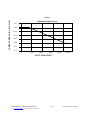
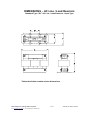
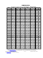
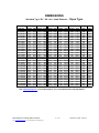
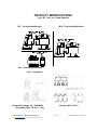
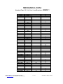
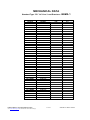
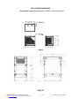
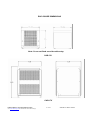
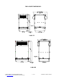
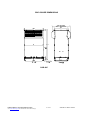
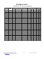
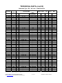
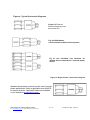
MTE Corporation
MTE –Series RL
Line/ load Reactors
USER MANUAL
PART NO. INSTR -011
REL. 050516
© 2002 MTE Corporation
IMPORTANT USER INFORMATION
NOTICE
MTE Series RL Line/Load Reactors are components designed to improve the reliability
of adjustable frequency drives, DC drives and a wide variety of other types of power
electronic equipment. In addition they provide input line current harmonic mitigation and
long lead protection for inverter fed motors. MTE reactors are available in a large number
of current ratings and a variety of inductance values. The suitability of a line/load reactor
for a specific application must therefore be ultimately determined by the customer. In no
event will MTE Corporation assume responsibility or liability for any direct or
consequential damages resulting from the use or application of reactors. Nor will MTE
Corporation assume patent liability with respect to the use of information, circuits or
equipment described in this instruction manual.
Data subject to change without notice
See www.mtecorp.com for current data and CAD drawings
2 of 27
INSTR-011 REL. 050516
TABLE OF CONTENTS
1. Safety…………………………………………………………………………………
4
2. Introduction ...................................................................................................
5
3. Model Number Codes........................................................................................
6
4. Specifications ....................................................................................................
7
Altitude Derating Curve ...................................................................................
8
Dimensions & Technical Data ………….. .....................................................
Open Type
....…………... ……………………………………………… ......
NEMA Type 1 …….………………………………………………………………...
9
10
13
5. Installation Instructions ......................................................................................
21
Power Wiring Connection ............................................................................. ..
22
Grounding ..................................................................................................... ..
23
Typical Connection Diagrams ........................................................................ ..
24
6. Startup……………………………………………………………….……………….
25
7. Performance…………………………………………………………….……………
26
Data subject to change without notice
See www.mtecorp.com for current data and CAD drawings
3 of 27
INSTR-011 REL. 050516
1. IMPORTANT SAFETY INFORMATION
WARNING
ONLY A QUALIFIED ELECTRICIAN CAN CARRY OUT THE ELECTRICAL
INSTALLATION OF LINE/LOAD REACTORS
WARNING
High voltage is used in the operation of line/load reactors. Use Extreme caution to avoid contact
with high voltage when operating, installing or repairing equipment containing line/load
reactors. INJURY OR DEATH MAY RESULT IF SAFETY PRECAUTIONS ARE NOT
OBSERVED.
Line/load reactors are used in conjunction with inverters, or other electrical equipment that may
feedback lethal voltages. Follow the safety instructions in the equipment used with the reactor in
addition to the safety instruction in this manual.
WARNING
The opening of the branch circuit protective device may be an indication that a fault current has been
interrupted. To reduce the risk of fire or electrical shock, line/load reactors should be examined and
replaced if damaged.
WARNING
An upstream disconnect/protection device must be used as required by the National Electrical Code
(NEC).
WARNING
Even if the upstream disconnect/protection device is open, a drive or inverter down stream of the
line/load reactor may feed back high voltage to the reactor. The inverter or drive safety instructions
must be followed. INJURY OR DEATH MAY RESULT IF THE DRIVE SAFETY
PRECAUTIONS ARE NOT OBSERVED.
WARNING
The frame of line/load reactors must be grounded at least at one of the reactor’s mounting holes.
WARNING
Only spare parts obtained from MTE Corporation or an authorized MTE distributor can be used
Data subject to change without notice
See www.mtecorp.com for current data and CAD drawings
4 of 27
INSTR-011 REL. 050516
2. INTRODUCTION
This manual was specifically developed to assist in the installation, interconnection and operation of
MTE Corporation Series RL Line/Load Reactors
This manual is intended for use by personnel experienced in the operation and maintenance of electronic
drives, inverters and similar types of power electronic equipment. Because of the high voltages required by the
equipment connected to line/load reactors and the potential dangers presented by rotating machinery, it is
essential that all personnel involved in the operation and maintenance of line/load reactors know and practice
the necessary safety precautions for this type of equipment. Personnel should read and understand
the instructions contained in this manual before installing, operating or servicing line/load reactors and
the drive to which the reactor is connected.
Upon Receipt of a Reactor:
MTE Line/load Reactors have been subjected to demanding factory tests before shipment. Carefully
inspect the shipping container for damage that may have occurred in transit. Then unpack the filter and
carefully inspect for any signs of damage. Save the shipping container for future transport of the
reactor.
In the event of damage, please contact and file a claim with the freight carrier involved
immediately.
If the equipment is not going to be put into service upon receipt, cover and store the reactor in a clean, dry
location. After storage, ensure that the equipment is dry and that no condensation has accumulated on
the reactor before applying power.
Repair/Exchange Procedure
MTE Corporation requires a Returned Material Authorization Number before it can accept any reactors
that qualify for return or repair. If problems or questions arise during installation, setup, or operation of the filter,
please call us for assistance at:
Phone: 1-262-253-8200
FAX: 1-262-253-8222
Data subject to change without notice
See www.mtecorp.com for current data and CAD drawings
5 of 27
INSTR-011 REL. 050516
3. MODEL NUMBER CODES
Standard RL Reactor model number codes are of the form RL ABCDEF(GHI) with the
number coded as outlined below.
Table 1 Model Number Codes
Character
Description
RLA,B,C,D
Code
Always for Harmonic Compensated
Line/Load Reactor
Characters A, B, C,(D), designate the
Fundamental Current rating of the
Reactor using 2 leading zeros (up to 8
Amps), 1 leading zero (12 to 80 Amps),
no leading zeros (100 to 950 Amps),
and 4-th digit (1,000 Amps and higher)
G,H,I
Reactor
Indicates mechanical configuration
0 Open
1 or 4 NEMA-1 Std Cabinet
2 NEMA-1, Over size Cabinet
3 NEMA 3R
Relative% Impedance number based on
480 Volts
1,2,3,4
Modifications
A Omit Center coil
E
F
Example: 080XXis an 80Amp
B Terminal Modifications
D Sub. Black Paint for Blue
T Temperature Switches
Data subject to change without notice
See www.mtecorp.com for current data and CAD drawings
6 of 27
INSTR-011 REL. 050516
4. SPECIFICATIONS
AGENCY APPROVALS:
UL-508, File E180243 Component Listed (1 amp – 2400 amps)
UL-508, File E180243 UL Listed Nema 1 units (1 amp – 2400 amps) CSA C22.2, File LR29753-13
CR CSA Certified (1 amp – 2400 amps) Class N, 200 C, File E66214, Type 200-18, UL Recognized
CE Marked Insulation System
Inductance Tolerance:
+/- 10 %
Current Rating: Refer to motor nameplate: Reactor fundamental amps Equal or Exceed motor FLA
Voltage Rating:
Refer to product nameplate Dielectric Strength: 4000 Volts RMS, 5600
Volts Peak dv/dt Protection:17,825 volts/microsecond
Maximum Carrier Switching Frequency:
20 KHz
Insulation System Class:
N
Ambient temperature:
-40°C to +45°C
Storage temperature -40°C to +90°C
Average Temperature Rise: 135°C
Altitude (See chart 1 for altitude derating curve): 3300 Ft. Max.
Maximum Fundamental Frequency without derating:
Color:
60 / 50 Hz consult factory for derating
Royal Blue
Data subject to change without notice
See www.mtecorp.com for current data and CAD drawings
7 of 27
INSTR-011 REL. 050516
CURRENT DERATING FACTOR
Chart 1
Altitude Derating Curve
1.05
1.00
0.95
0.90
0.85
0.80
0.75
0.70
0
3300
6600
9900
13200
16500
ALTITUDE (FEET)
Data subject to change without notice
See www.mtecorp.com for current data and CAD drawings
8 of 27
INSTR-011 REL. 050516
DIMENSIONS – AC Line / Load Reactors
Standard Type “RL” AC Line / Load Reactors - Open Type
Tables that follow contain reactor dimensions
Data subject to change without notice
See www.mtecorp.com for current data and CAD drawings
9 of 27
INSTR-011 REL. 050516
DIMENSIONS
Standard Type “RL” AC Line / Load Reactors – Open
MTE
Ca t. No.
RL-00201
RL-00202
RL-00203
RL-00204
RL-00401
RL-00402
RL-00403
RL-00404
RL-00801
RL-00802
RL-00803
RL-00804
RL-01201
RL-01202
RL-01203
RL-01801
RL-01802
RL-01803
RL-02501
RL-02502
RL-02503
RL-03501
RL-03502
RL-03503
RL-04501
RL-04502
RL-04503
RL-05501
RL-05502
RL-05503
RL-08001
RL-08002
RL-08003
RL-10001
RL-10002
RL-10003
RL-13001
RL-13002
RL-13003
RL-16001
RL-16002
RL-16003
RL-20001
RL-20002
RL-20003
RL-25001B1
RL-25002B1
RL-25003B1
A
Inche s
4.4
4.4
4.4
4.4
4.4
4.4
4.4
4.4
6.0
6.0
6.0
6.0
6.0
6.0
6.0
6.0
6.0
8.1
7.2
7.2
7.2
7.2
7.2
9.0
9.0
9.0
9.0
9.0
9.0
9.0
10.0
10.8
10.8
10.8
10.8
10.8
9.0
10.8
11.0
10.8
10.8
11.5
10.8
10.8
10.8
10.8
14.4
14.4
B
m m Inche s
112
4.1
112
4.1
112
4.1
112
4.1
112
4.1
112
4.1
112
4.1
112
4.1
152
4.8
152
4.8
152
4.8
152
4.8
152
5.0
152
5.0
152
5.0
152
5.3
152
5.3
206
6.1
183
5.8
183
5.8
183
5.8
183
5.8
183
5.8
229
7.4
229
7.4
229
7.4
229
7.3
229
7.3
229
7.0
229
7.0
254
8.5
274
8.5
274
8.5
274
8.6
274
8.3
274
8.3
229
7.0
274
8.4
279
8.5
274
8.3
274
8.3
292
8.5
274
8.3
274
8.3
274
8.3
274
8.3
366
11.4
366
11.2
C
m m Inche s
104
2.8
104
2.8
104
2.8
104
2.5
104
2.8
104
2.8
104
3.4
104
3.4
122
3.0
122
3.0
122
3.4
122
3.4
127
3.3
127
3.3
127
3.9
135
3.2
135
3.5
155
4.0
147
3.5
147
3.5
147
4.3
147
4.0
147
4.0
188
4.7
188
4.7
188
4.7
185
5.3
185
5.3
178
5.3
178
6.0
216
6.3
216
6.5
216
6.8
217
5.5
210
5.7
210
6.2
179
4.7
213
5.7
216
6.2
211
5.2
211
6.0
216
9.0
211
6.0
211
8.3
211
9.0
211
9.0
290
10.0
284
11.3
D
m m Inche s
71
1.98
71
1.98
71
1.98
64
1.73
71
1.98
71
1.98
86
2.35
86
2.60
76
2.10
76
2.10
86
2.62
86
2.48
84
2.10
84
2.10
99
2.75
81
2.10
89
2.48
102
2.60
89
2.35
89
2.35
109
3.10
102
2.60
102
2.75
119
3.16
119
3.16
119
3.16
135
3.66
135
3.16
135
3.16
152
3.91
159
3.47
165
3.47
173
4.16
139
3.30
144
3.66
156
4.16
118
3.16
144
3.66
156
4.16
131
3.16
152
3.47
229
4.69
152
4.16
210
4.41
229
5.91
229
4.19
254
5.16
286
5.82
mm
50.3
50.3
50.3
43.9
50.3
50.3
59.7
66.0
53.3
53.3
66.5
63.0
53.3
53.3
69.9
53.3
63.0
66.0
59.7
59.7
78.7
66.0
69.9
80.3
80.3
80.3
93.0
80.3
80.3
99.3
88.1
88.1
105.7
83.8
93.0
105.7
80.3
93.0
105.7
80.3
88.1
119.1
105.7
112.0
150.1
106.4
131.1
147.8
E
Inche s
1.44
1.44
1.44
1.44
1.44
1.44
1.44
1.44
2.00
2.00
2.00
2.00
2.00
2.00
2.00
2.00
2.00
3.00
3.00
3.00
3.00
3.00
3.00
3.00
3.00
3.00
3.00
3.00
3.00
3.00
3.63
3.63
3.63
3.63
3.63
3.63
3.00
3.63
3.63
3.63
3.63
3.63
3.63
3.63
3.63
3.63
4.60
4.60
Type
mm
36.6
36.6
36.6
36.6
36.6
36.6
36.6
36.6
50.8
50.8
50.8
50.8
50.8
50.8
50.8
50.8
50.8
76.2
76.2
76.2
76.2
76.2
76.2
76.2
76.2
76.2
76.2
76.2
76.2
76.2
92.2
92.2
92.2
92.2
92.2
92.2
76.2
92.2
92.2
92.2
92.2
92.2
92.2
92.2
92.2
92.2
116.8
116.8
W e ight Ma ss
Lbs
Kg
4
1.8
4
1.8
4
1.8
3
1.4
4
1.8
4
1.8
5
2.3
6
2.7
7
3.2
8
3.6
11
5.0
13
5.9
9
4.1
10
4.5
18
8.2
9
4.1
12
5.4
16
7.3
11
5.0
14
6.3
20
9.1
14
6.3
16
7.3
30
14
23
10
28
13
39
18
24
11
27
12
41
19
43
20
51
23
61
28
47
21
51
23
74
34
29
13
57
26
64
29
40
18
50
23
67
30
48
22
67
30
100
45
68
31
106
48
140
63
See www.mtecorp.com “Line load Reactors” for current dimensions and CAD details
Data subject to change without notice
See www.mtecorp.com for current data and CAD drawings
10 of 27
INSTR-011 REL. 050516
DIMENSIONS
Standard Type “RL” AC Line / Load Reactors – Open
MTE
Cat. No.
RL-32001B1
RL-32002B1
RL-32003B1
RL-40001B1
RL-40002B1
RL-40003B1
RL-50001
RL-50002
RL-50003
RL-60001
RL-60002
RL-60003
RL-75001
RL-75002
RL-75003
RL-85001
RL-85002
RL-85003
RL-100001
RL-100002
RL-100003
RL-120001
RL-120002
RL-120003
RL-140001
RL-140002
RL-140003
RL-150001
RL-150002
RL-150003
A
Inches
14.4
14.4
15.0
14.5
15.5
15.5
15.5
15.5
15.5
15.5
15.5
15.5
22.0
22.0
22.0
20.3
22.0
22.5
21.6
20.3
20.3
22.5
22.5
22.5
22.0
22.0
22.0
22.0
22.0
22.0
Type
Weight Mass
B
C
D
E
mm Inches mm Inches mm Inches mm Inches mm
Lbs
Kg
366 11.4 288 10.0 254 5.16 131.1 4.60 116.8
110
50
366 11.3 286 10.5 267 5.88 149.4 4.60 116.8
125
57
381 11.3 286 13.0 330 7.13 181.1 4.60 116.8
190
86
368 11.3 286 10.0 254 5.16 131.1 4.60 116.8
100
45
394 11.3 286 12.1 307 6.76 171.7 4.60 116.8
155
70
394 11.3 286 14.5 368 7.26 184.4 4.60 116.8
200
91
394 11.5 291 10.5 267 5.50 139.7 4.60 116.8
120
54
394 11.5 292 15.0 381 6.76 171.7 4.60 116.8
180
82
394 11.5 292 14.8 375 9.76 247.9 4.60 116.8
290
132
394 11.5 292 13.0 330 5.26 133.6 4.60 116.8
160
73
394 11.0 279 13.0 330 8.00 203.2 4.60 116.8
210
95
394 11.4 290 15.5 394 9.26 235.2 4.60 116.8
290
132
559 16.5 419 11.5 291 6.63 168.4 7.20 182.9
200
91
559 16.5 419 14.0 356 8.01 203.5 7.20 182.9
310
141
559 16.8 425 18.0 457 9.26 235.2 7.20 182.9
400
181
514 16.8 425 12.0 305 7.60 193.0 7.20 182.9
320
145
559 16.8 425 15.0 381 8.00 203.2 7.20 182.9
380
172
572 16.8 427 18.0 457 9.00 228.6 7.20 182.9
460
209
549 16.8 425 14.5 368 7.26 184.4 7.20 182.9
320
145
514 16.8 425 14.0 356 8.50 215.9 7.20 182.9
420
190
514 16.8 425 15.0 381 10.76 273.3 7.20 182.9
625
283
572 17.0 432 15.0 381 11.00 279.4 7.20 182.9
425
193
572 17.0 432 18.0 457 10.76 273.3 7.20 182.9
545
247
572 17.0 432 18.0 457 11.00 279.4 7.20 182.9
690
313
559 17.0 432 22.0 559 11.00 279.4 7.20 182.9
500
227
559 17.0 432 22.0 559 11.00 279.4 7.20 182.9
630
286
559 17.0 432 22.0 559 11.00 279.4 7.20 182.9
850
385
559 17.0 432 22.0 559 11.00 279.4 7.20 182.9
635
288
559 17.0 432 22.0 559 11.00 279.4 7.20 182.9
675
306
559 17.0 432 22.0 559 11.00 279.4 7.20 182.9
900
408
See www.mtecorp.com “Line load Reactors” for current dimensions and CAD details
Data subject to change without notice
See www.mtecorp.com for current data and CAD drawings
11 of 27
INSTR-011 REL. 050516
PRODUCT MODIFICATIONS
Type “RL” AC Line / Load Reactors
“B1” Terminal Modification
“B14” Terminal Modification
“B8” Terminal Modification
“SLU” Lug Option
Single Wire Range: 00 – 500 MCM
Stranding Class “B”& “C” only
Data subject to change without notice
See www.mtecorp.com for current data and CAD drawings
Shown On RL-25001
12 of 27
INSTR-011 REL. 050516
MECHANICAL DATA
Standard Type “RL” AC Line / Load Reactors – NEMA
Catalog
Cabinet
Weight
Mass
Number
Number
RL-00211
RL-00212
RL-00213
RL-00214
RL-00411
RL-00412
RL-00413
RL-00414
RL-00811
RL-00812
RL-00813
RL-00814
RL-01211
RL-01212
RL-01213
RL-01811
RL-01812
RL-01813
RL-02511
RL-02512
RL-02513
RL-03511
RL-03512
RL-03513
RL-04511
RL-04512
RL-04513
RL-05511
RL-05512
RL-05513
RL-08011
RL-08012
RL-08013
RL-10011
RL-10012
RL-10013
RL-13011
RL-13012
RL-13013
RL-16011
RL-16012
RL-16013
RL-20011
CAB-8
Lbs
11
11
11
10
11
11
12
13
14
15
18
20
16
17
25
16
19
47
42
45
49
45
47
61
54
59
70
55
58
72
74
82
86
78
86
105
60
88
95
71
81
98
79
Kg
5
Data subject to change without notice
See www.mtecorp.com for current data and CAD drawings
CAB-8
CAB-8
CAB-8
CAB-8
CAB-8
CAB-8
CAB-8
CAB-8
CAB-8
CAB-8
CAB-8
CAB-8
CAB-8
CAB-8
CAB-8
CAB-8
CAB-13V
CAB-13V
CAB-13V
CAB-13V
CAB-13V
CAB-13V
CAB-13V
CAB-13V
CAB-13V
CAB-13V
CAB-13V
CAB-13V
CAB-13V
CAB-13V
CAB-13V
CAB-13V
CAB-13V
CAB-13V
CAB-13V
CAB-13V
CAB-13V
CAB-13V
CAB-13V
CAB-13V
CAB-13V
CAB-13V
13 of 27
1
5
5
5
5
5
6
6
7
7
8
9
7
8
11
7
9
21
19
21
22
21
22
23
25
27
32
25
27
33
34
37
39
36
39
48
27
40
43
32
37
45
36
INSTR-011 REL. 050516
MECHANICAL DATA
Standard Type “RL” AC Line / Load Reactors – NEMA
Catalog
Number
RL-20012
RL-20013
RL-25011B1
RL-25012B1
RL-25013B1
RL-32011B1
RL-32012B1
RL-32013B1
RL-40011B1
RL-40012B1
RL-40013B1
RL-50011
RL-50012
RL-50013
RL-60011
RL-60012
RL-60013
RL-75041
RL-75042
RL-75043
RL-85041
RL-85042
RL-85043
RL-100041
RL-100042
RL-100042
RL-100043
RL-120041
RL-120042
RL-120043
RL-140041
RL-140042
RL-150021
RL-150042
RL-150043
RL-180041
RL-180042
RL-180043
RL-210041
RL-210042
RL-210043
Data subject to change without notice
See www.mtecorp.com for current data and CAD drawings
Cabinet
Number
CAB-13V
CAB-13V
CAB-13V
CAB-17V
CAB-17V
CAB-17V
CAB-17V
CAB-17V
CAB-17V
CAB-17V
CAB-17V
CAB-17V
CAB-17V
CAB-17V
CAB-17V
CAB-17V
CAB-17V
CAB-30B
CAB-30B
CAB-30B
CAB-30B
CAB-30B
CAB-30B
CAB-30B
CAB-30B
CAB-30B
CAB-30B
CAB-30B
CAB-30B
CAB-30B
CAB-42C
CAB-42C
CAB-42C
CAB-42C
CAB-42C
CAB-42C
CAB-42C
CAB-42C
CAB-42C
CAB-42C
CAB-42C
14 of 27
Weight
Lbs
98
131
99
151
185
155
170
235
145
200
245
165
225
335
205
255
335
283
393
483
1
Mass
Kg
45
60
45
69
84
70
77
107
66
91
111
75
102
152
93
116
152
129
179
220
INSTR-011 REL. 050516
ENCLOSURE DIMINSIONS
Top conduit entry recommended for NEMA 1 enclosed reactors.
CAB-8
CAB-12C
Data subject to change without notice
See www.mtecorp.com for current data and CAD drawings
15 of 27
INSTR-011 REL. 050516
ENCLOSURE DIMENSIONS
Note: Cover not fixed use side cable entry.
CAB-13V
CAB-17V
Data subject to change without notice
See www.mtecorp.com for current data and CAD drawings
16 of 27
INSTR-011 REL. 050516
ENCLOSURE DIMENSIONS
CAB-17C
CAB-30B
Data subject to change without notice
See www.mtecorp.com for current data and CAD drawings
17 of 27
INSTR-011 REL. 050516
ENCLOSURE DIMENSIONS
CAB-42C
Data subject to change without notice
See www.mtecorp.com for current data and CAD drawings
18 of 27
INSTR-011 REL. 050516
TECHNICAL DATA
Standard Type “RL” AC Line / Load Reactors
Catalog
Terminal Data
Number
Watts
Loss
Type
RL-00201
RL-00202
RL-00203
RL-00204
RL-00401
RL-00402
RL-00403
RL-00404
RL-00801
RL-00802
RL-00803
RL-00804
RL-01201
RL-01202
RL-01203
RL-01801
RL-01802
RL-01803
RL-02501
RL-02502
RL-02503
RL-03501
RL-03502
RL-03503
RL-04501
RL-04502
RL-04503
RL-05501
RL-05502
RL-05503
RL-08001
RL-08002
RL-08003
8
12
16
11
15
20
20
21
20
29
26
28
26
31
41
36
43
43
48
52
61
49
54
54
54
62
65
64
67
71
82
86
96
TB
TB
TB
TB
TB
TB
TB
TB
TB
TB
TB
TB
TB
TB
TB
TB
TB
TB
TB
TB
TB
TB
TB
TB
TB
TB
TB
Box
Box
Box
Box
Box
Box
Wire Range(AWG) Torque (in – lbs)
22 – 14
22 – 14
22 – 14
22 – 14
22 – 14
22 – 14
22 – 14
22 – 14
22 – 14
22 – 14
22 – 14
22 – 14
22 – 5
22 – 5
22 – 5
22 – 5
22 – 5
22 – 5
22 – 5
22 – 5
22 – 5
22 – 5
22 – 5
18 – 4
18 – 4
18 – 4
18 – 4
6 – 1/0
6 – 1/0
6 – 1/0
6 – 1/0
6 – 1/0
6 – 1/0
Data subject to change without notice
See www.mtecorp.com for current data and CAD drawings
4.5
4.5
4.5
4.5
4.5
4.5
4.5
4.5
4.5
4.5
4.5
4.5
16
16
16
16
16
16
16
16
16
16
16
20
20
20
20
6-4(45) & 2-0(50)
6-4(45) & 2-0(50)
6-4(45) & 2-0(50)
6-4(45) & 2-0(50)
6-4(45) & 2-0(50)
6-4(45) & 2-0(50)
19 of 27
Weight
Mass
Fund
lbs
Kg
mH
4
4
4
3
4
4
5
6
7
8
11
13
9
10
18
9
12
16
11
14
18
14
16
30
23
28
39
24
27
41
43
51
55
2
2
2
2
2
3
2
3
4
4
5
6
4
5
9
4
6
8
5
7
9
7
8
14
10
13
18
11
12
18
19
23
25
12
20
32
6
3
6.5
9
12
1.5
3
5
7.5
1.25
2.5
4.2
0.8
1.5
2.5
0.5
1.2
1.8
0.4
0.8
1.2
0.3
0.7
1.2
0.25
0.5
0.85
0.2
0.4
0.7
Max
Amp
Amps
s
2
3
2
3
2
3
2
3
4
6
4
6
4
6
4
6
8
12
8
12
8
12
8
12
12
18
12
18
12
18
18
27
18
27
18
27
25
37.5
25
37.5
25
37.5
35
52.5
35
52.5
35
52.5
45
67.5
45
67.5
45
67.5
55
82.5
55
82.5
55
82.5
80
120
80
120
80
120
INSTR-011 REL. 050516
TECHNICAL DATA (cont’d)
Standard Type “RL” AC Line / Load Reactors
Catalog
Watts
Loss
Number
(watts) Type Wire Range(AWG)
Terminal Data
RL-10001
94
Box
6 – 1/0
RL-10002
84
Box
6 – 1/0
RL-10003
108
Box
6 – 1/0
RL-13001
108
Box
2 – 4/0
RL-13002
180
Box
2 – 4/0
RL-13003
128
Box
2 – 4/0
RL-16001
116
Box
2 – 4/0
RL-16002
149
Box
2 – 4/0
RL-16003
138
Box
2 – 4/0
RL-20001
124
Box
2 – 4/0
RL-20002
168
Box
2 – 4/0
RL-20003
146
Box
2 – 4/0
RL-25001B1
154
Tab
Copper Tab
RL-25002B1
231
Tab
Copper Tab
RL-25003B1
219
Tab
Copper Tab
RL-32001B1
224
Tab
Copper Tab
RL-32002B1
264
Tab
Copper Tab
RL-32003B1
351
Tab
Copper Tab
RL-40001B1
231
Tab
Copper Tab
RL-40002B1
333
Tab
Copper Tab
RL-40003B1
293
Tab
Copper Tab
RL-50001
266
Tab
Copper Tab
RL-50002
340
Tab
Copper Tab
RL-50003
422
Tab
Copper Tab
RL-60001
307
Tab
Copper Tab
RL-60002
414
Tab
Copper Tab
RL-60003
406
Tab
Copper Tab
RL-75001
427
Tab
Copper Tab
RL-75002
630
Tab
Copper Tab
RL-75003
552
Tab
Copper Tab
RL-85001
798
Tab
Copper tab
RL-85002
930
Tab
Copper tab
RL-85003
1133
Tab
Copper tab
RL-90001
860
Tab
Copper tab
RL-90002
1020
Tab
Copper tab
RL-90003
1365
Tab
Copper tab
RL-100001
940
Tab
Copper tab
RL-100002
1090
Tab
Copper tab
RL-100003
1500
Tab
Copper tab
RL-120001
980
Tab
Copper tab
RL-120002
1130
Tab
Copper tab
RL-120002
1550
Tab
Copper tab
RL-140001
Tab
Copper tab
RL-140002
1523
Tab
Copper tab
RL-140003
1680
Tab
Copper tab
RL-150001
1432
Tab
Copper tab
RL-150002
1671
Tab
Copper tab
RL-150003
1815
Tab
Copper tab
Contact factory for higher ratings.
Data subject to change without notice
See www.mtecorp.com for current data and CAD drawings
Weight Mass
Wire
Range(AWG)
6-4(45) & 2-0(50)
6-4(45) & 2-0(50)
6-4(45) & 2-0(50)
150
150
150
150
150
150
150
150
150
Not Applicable
Not Applicable
Not Applicable
Not Applicable
Not Applicable
Not Applicable
Not Applicable
Not Applicable
Not Applicable
Not Applicable
Not Applicable
Not Applicable
Not Applicable
Not Applicable
Not Applicable
Not Applicable
Not Applicable
Not Applicable
Not Applicable
Not Applicable
Not Applicable
Not Applicable
Not Applicable
Not Applicable
Not Applicable
Not Applicable
Not Applicable
Not Applicable
Not Applicable
Not Applicable
Not Applicable
Not Applicable
Not Applicable
Not Applicable
Not Applicable
Not Applicable
20 of 27
lbs
Kg
47
51
74
29
57
64
40
50
67
48
67
100
68
106
140
110
125
190
100
155
200
120
180
290
160
210
290
200
310
400
313
370
454
21
23
33
13
26
29
18
22
31
22
31
46
31
49
64
50
57
86
46
71
91
55
82
132
73
96
132
91
141
182
143
168
207
350
409
589
385
440
604
159
186
268
175
200
275
522
627
551
630
680
238
285
251
287
309
mH
0.15
0.3
0.45
0.1
0.2
0.3
0.075
0.15
0.23
0.055
0.11
0.185
0.045
0.09
0.15
0.04
0.075
0.125
0.03
0.06
0.105
0.025
0.05
0.085
0.02
0.04
0.065
0.015
0.029
0.048
0.015
0.027
0.042
0.013
0.025
0.04
0.011
0.022
0.038
0.009
0.019
0.03
0.008
0.016
0.027
0.008
0.015
0.025
Fund
Max
Amps
Amps
100
100
100
130
130
130
160
160
160
200
200
200
250
250
250
320
320
320
400
400
400
500
500
500
600
600
600
750
750
750
850
850
850
900
900
900
1000
1000
1000
1200
1200
1200
1400
1400
1400
1500
1500
1500
150
150
150
195
195
195
240
240
240
300
300
300
375
375
375
480
480
480
560
560
560
700
700
700
840
840
750
1050
1050
938
1063
1063
1063
1125
1125
1125
1250
1250
1250
1500
1500
1500
1750
1750
1750
1875
1875
1875
INSTR-011 REL. 050516
5. INSTALLATION INSTRUCTIONS
Open Line/Load Reactor Installation
MTE line/load reactors are available in open construction and in NEMA 1 enclosures. Open reactors are
designed for mounting within an appropriate electrical equipment enclosure. Reactors rated 300
amperes RMS and under are designed for mounting in both a vertical and horizontal position. Larger
reactors must be mounted in a horizontal position typically on the floor of the enclosure. Include the power
dissipation of the reactor along with all the other components located in the enclosure to determine the
internal temperature rise and cooling requirements of the enclosure.
Reactors may be located in any region of the enclosure where the ambient temperature does not exceed
45 degrees C. Allow a minimum side clearances of four (4) inches and vertical clearances of six (6) inches
for proper heat dissipation and access. Do not locate the reactor next to resistors or any other component
with operating surface temperatures above 125 degree C.
Select a well ventilated, dust-free area away from direct sunlight, rain or moisture. Do not install in or near a
corrosive environment. Avoid locations where the reactor will be subjected to excessive vibrations.
NEMA 1 Enclosed Line/Load Reactor Installation
Top conduit entry recommended for NEMA 1 enclosed reactor.
MTE line/load reactors mounted in enclosures with part number, CAB-8, are designed for wall
mounting. All other enclosures are designed for floor mounting.
WARNING
MTE NEMA 1 enclosure is designed for floor mounting must be mounted with the enclosure base
horizontal for proper ventilation. Wall mounting a floor mounted enclosure with the base
against the wall will cause the reactor to over heat resulting in equipment damage.
Allow a minimum side, front, and back clearances of twelve (12) inches and vertical clearances of
eighteen (18) inches for proper heat dissipation and access. Do not locate the enclosure next to resistors
or any other component with operating surface temperatures above 125 degree C.
Select a well ventilated, dust-free area away from direct sunlight, rain or moisture where the ambient
temperature does not exceed 40 degrees C.
Do not install in or near a corrosive environment.
Avoid locations where the reactor will be subjected to excessive vibrations.
Where desirable, enclosures may be mounted on vibration isolating pads to reduce audible noise.
Standard vibration control pads made from neoprene or natural rubber and selected for the weight of
the enclosed reactor are effective.
Data subject to change without notice
See www.mtecorp.com for current data and CAD drawings
21 of 27
INSTR-011 REL. 050516
Power Wiring Connection
WARNING
Input and output power wiring to the reactor should be performed by authorized personnel in
accordance with the NEC and all local electrical codes and regulations.
Verify that the power source to which the reactor is to be connected is in agreement with the nameplate
data on the reactor. A fused disconnect switch or circuit breaker should be installed between the reactor
and its source of power in accordance with the requirements of the NEC and all local electrical codes and
regulations. Refer to the drive, inverter, or other electrical equipment user manual for selection of the correct
fuse rating and class.
The reactor is suitable for use on a circuit capable of delivering not more than 65,000 rms symmetrical
amperes at 480 volts when protected by Bussman type JJS, KTK, KTK-R, SPP or T class fuses.
Reactor are designed for use with copper conductors with a minimum temperature rating of 75 degrees
C. Table 2 lists the wire range and terminal torque requirements for the power input and output
connections by reactor part number.
Refer to Figure 4 for typical electrical diagrams describing the application of reactors in both line and
load applications. For reactors supplied as a component part of a drive system or a component part of
power electronic apparatus follow the interconnection diagram supplied by the System Engineer.
Where desirable, a flexible conduit connection to the reactor enclosure should be made to reduce
audible noise.
WARNING
Failure to connect reactors supplied as a component part of a drive system or other power
electronic system according to the system interconnection diagram supplied by the System
Engineer will result in equipment damage, injury, or death.
WARNING
If a line reactor or a line reactor and a load reactor are used with a drive equipped with a bypass
circuit, the reactors must be removed from the motor circuit in the bypass mode. Damage to the
motor and other equipment will result if this warning is not observed.
Data subject to change without notice
See www.mtecorp.com for current data and CAD drawings
22 of 27
INSTR-011 REL. 050516
Grounding
A stud is provided on enclosed reactors for grounding the enclosure. The enclosure must
be grounded. Open reactors must be grounded at the designated grounding terminal or the
reactor mounting holes if no designated grounding terminal is provided.
WARNING
The frame of line/load reactors must be grounded at the designated grounding terminal or one of
the reactor mounting holes if no designated grounding terminal is provided. The enclosure of
reactors supplied in enclosures must be grounded. INJURY OR DEATH MAY RESULT IF SAFETY
PRECAUTIONS ARE NOT OBSERVED.
Data subject to change without notice
See www.mtecorp.com for current data and CAD drawings
23 of 27
INSTR-011 REL. 050516
Figure 4 –Typical Connection Diagrams
Fig 4a LINE Reactor
Connects between power
source and VFD
Fig. 4b LOAD Reactor
Connects between ASD and load (motor)
Fig 4c Use individual Line Reactors for
multiple drives connected to a common power
source
Figure 5.Single Phase connection diagram.
Standard three phase reactors may be used for single
phase applications. Refer to application note AN0102
for proper selection. Application Notes are available
on our website at www.mtecorp.com.
Data subject to change without notice
See www.mtecorp.com for current data and CAD drawings
24 of 27
INSTR-011 REL. 050516
6. STARTUP
Safety Precautions
Before startup, observe the following warnings and instructions:
WARNING
A Reactor is at line potential when the Reactor is connected to the utility. This voltage is extremely
dangerous and may cause death or severe injury if you come in contact with it.
WARNING
High voltage is used in the operation of line/load reactors. Use Extreme caution to avoid
contact with high voltage when operating, installing or repairing equipment containing
line/load reactors. Line/load reactors are used in conjunction with inverters, or other
electrical equipment that may feedback lethal voltages.
Follow the safety instructions in the equipment used with the reactor in addition to the safety instruction in
this manual.
INJURY OR DEATH MAY RESULT IF SAFETYPRECAUTIONS ARE NOT OBSERVED.
Sequence of Operation
1. Read and follow safety precautions.
2. After installation, ensure that:
x All Reactor ground terminals are connected to ground.
x Power wiring to the utility, drive and motor is in accordance with the interconnection diagrams
supplied by the System Engineer.
3. Check that moisture has not condensed on the Reactor. If moisture is present, do not proceed
with startup until the moisture has been removed.
4. Proceed with startup according to the instructions provided by the system supplier.
WARNING
Reactors are a component part of an electrical system. Do not proceed with startup until the system
startup instructions provided by the System Engineer are understood and followed. Injury, death
and damage to equipment may result if the system startup instructions are not followed.
WARNING
Use extreme caution to avoid contact with line voltage when checking for power. INJURY OR
DEATH MAY RESULT IF SAFETY PRECAUTIONS ARE NOT OBSERVED.
Data subject to change without notice
See www.mtecorp.com for current data and CAD drawings
25 of 27
INSTR-011 REL. 050516
PRODUCT Performance
Standard Type “RL” AC Line / Load Reactors
AUDIBLE NOISE:
Guard-AC Line/Load Reactors offer low noise operation. Core and coil
construction, flux density control, harmonic compensation as well as our epoxy impregnation
process assure minimal audible noise radiation. Although our reactors are typically “quiet”,
waveforms vary by drive type and application and therefore reactor audible noise may vary by
application. Noise levels may be affected by type of motor and motor conductor as well as motor
conductor length.
Typical audible noise levels for units selected from our catalog by HP rating are:
2 thru 12 amps
55 dBA
18 thru 100 amps
65 dBA
130 thru 400 amps 70 dBA
500 thru 1200 amps 75 dBA
Service Factor:
Guard-AC reactors are compensated for the additional currents and high
frequencies caused by the presence of harmonics. The reactor fundamental current rating
indicates the typical full load motor current. Standard reactors rated 2 amps thru 400 amps offer a
full 1.5 service factor rating which allows them to carry overload current up to 150% of their
fundamental rating when applied as an input line reactor. Since the nameplate ratings of motor
drives (ASD) varies widely by manufacturer, this helps to assure that the reactor maximum current
rating is compatible with the nameplate current rating on the ASD. Units rated above 400 amps to
750 amps have service factors of 1.25 or higher. The service factor rating compensates for ASD
manufacturer variances in motor drive current ratings and for harmonic currents. Nominal
inductance is assured all the way up to the service factor current rating.
PWM / IGBT PROTECTION: Guard-AC reactors are protected against the high peak voltage and
fast rise time voltage pulses associated with PWM waveforms. The dielectric strength is 4000
volts rms and Guard-AC reactors meet the ratings of an inverter duty motor (NEMA MG-1, part 31).
For convenience, they can be located either at the motor or at the drive.
HARMONIC ATTENUATION:
Our unique harmonic compensation assures maximum circuit
inductance in the presence of complex waveforms and can be relied upon to minimize input total
harmonic current distortion (THID). Additionally it offers superior absorption of transient voltage
spikes. Our standard reactors will typically reduce 6-pulse rectifier input current harmonics to the
following levels at full load operating conditions:
3% reactor alone
45% or less THID
5% reactor alone
35% or less THID
3% AC reactor + 3% DC link choke
33% or less THID
5% AC reactor + 3% DC link choke
28% or less THID
(DC link choke inductance is basis of % ac impedance).
Reactor Surface Temperature:
MTE RL reactors are optimized incorporating UL approved
insulation and flux technology designed to operate at temperatures up to 200°C. Surface
temperatures greater than 160°C at nominal ambient are considered hot. Reactors used for output
filtering will tend to run hotter from higher harmonics. Excessive Long motor leads can resonate
and produce additional heat. 8 KHz inverter switching frequency will push the reactor temperature
even higher. To reduce RL operating temperatures and minimize motor dV/dT terminal voltage set
the inverter frequency to 2KHz. Additional reactor heating will occur if added output capacitance
sets up an undesirable resonance. MTE does not recommend using the RL reactors with
supplemental filter capacitors.
Data subject to change without notice
See www.mtecorp.com for current data and CAD drawings
26 of 27
INSTR-011 REL. 050516
MTE Series RL Line/Load Reactor User Manual
Revision
---
Date
5/16/05
INSTR-011
Revision History
New document written by Wayne Walcott.
Data subject to change without notice
See www.mtecorp.com for current data and CAD drawings
27 of 27
INSTR-011 REL. 050516