1
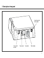
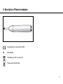
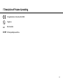
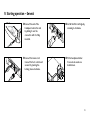
Instructions for use
Symbols
WARNING!
(Risk of injury)
ATTENTION!
(to prevent damage occurring)
General explanations,
without risk to
persons or objects
Thermo washer disinfectable
Sterilizable
up to the stated temperature
Data Matrix Code for product
identification e.g. in hygienic
maintenance process
Only for USA
Caution: Federal law restricts this device to sale by or on the order of a dentist,
physician or any other practitioner licensed by the law of the state in which he or she
practices to use or order the use of the device.
2
Contents
1.
2.
3.
4.
5.
6.
7.
8.
9.
10.
11.
12.
13.
14.
15.
16.
17.
18.
19.
20.
Introduction ....................................................................................................................................................................................4 – 5
Ozone generation ..................................................................................................................................................................................6
Equipment supplied ..............................................................................................................................................................................7
Description of front panel ....................................................................................................................................................................8
Description of rear panel ..............................................................................................................................................................9 – 10
Description of Prozone handpiece with tubing..................................................................................................................................11
Description of Prozone marking ........................................................................................................................................................12
Safety notes ..............................................................................................................................................................................13 – 14
Starting operation - General ................................................................................................................................................................15
Starting operation - Control Unit ........................................................................................................................................................16
Clinical applications .................................................................................................................................................................... 17– 20
Disinfection, Cleaning, Sterilization ..................................................................................................................................................21
Maintenance .............................................................................................................................................................................. 22– 23
Warnings ..............................................................................................................................................................................................24
Errors ..........................................................................................................................................................................................25 – 26
Environmental conditions ..................................................................................................................................................................27
Characteristics ..................................................................................................................................................................................28
Electromagnetics compatibility ................................................................................................................................................29 – 35
Accessories ........................................................................................................................................................................................36
Warranty ..............................................................................................................................................................................................37
3
1. Introduction
For your safety and the safety of your patients
These Instructions for Use explain how to use your product. However, we must also warn against possible hazardous situations. Your
safety, the safety of your team, and of course, the safety of your patients are of paramount importance to us.
It is therefore essential to read the safety notes.
Intended use
The Prozone is an electrical device which produces ozone for use in various dental applications.
Qualifications of the user
The Prozone has been designed and developed for the dental profession.
Only suitably qualified medical, technical and specialist staff may use the Prozone unit after specific training.
Production according to EU-Directives
EU-Directive 93/42/EEC has been used as a basis in the design and manufacture of this medical product and this applies to the
Prozone unit. This declaration does not apply to non-specified fittings, mountings etc.
4
Introduction
Responsibility of the manufacturer
Tip Top Tips (TTT) can only accept responsibility for the safety, reliability and performance of the Prozone when there is compliance
with the following directions:
> The Prozone must be used in accordance with these Instructions for use.
> The Prozone has no components which can be repaired by the user. Assembly, modifications or repairs must only be undertaken
by skilled personnel authorized by TTT.
> The electrical installation at the premises must comply with the regulations of ÖVE-EN 7 »Installation of electrical equipment in
rooms used for medical purposes« or with the regulations applicable in your country.
> Unauthorized opening of the Prozone invalidate all claims under warranty and any other claims.
5
2. Ozone generation
Generation of ozone is created with a high voltage applied on a ceramic plate, principle called corona discharge.
To produce ozone with the Corona effect, it is very important that the air inside the ozone generator chamber is dry.
The device will purge for 30 secs each time it is turned on (up to 90 sec if the air flow is reduced; for example with an Prozone tip
Endo connected).
This purge will ensure that the humidity that could remain in the Prozone while the device is not in use will be evacuated.
The purge can also be performed manually by depressing the 03 button while the device is in standby.
Only use the Prozone with a yellow filter
Humidity inside the ozone generator will:
> reduce the production of ozone.
> reduce the life time of the ceramic plate.
yellow
= good
blue/yellow = to be exchanged
blue
= expired (error CF)
The device will display an error (E2) when there is a low output of ozone. In this case, the Prozone will have to be re-calibrated by a
TTT appointed distributor.
6
3. Equipment supplied
❍ REF 12930100 Prozone unit
❍ Prozone handpiece tube with connector
❍ Prozone handpiece
❍ Prozone filter cartridge
❍ Prozone foot control
❍ Prozone tips Coro (20 pcs)
❍ Prozone tips Endo (20 pcs)
❍ Prozone tips Perio (20 pcs)
❍ IFU 50631 Prozone Instruction for use
Only one supplied:
❍ REF 01343700 Mains cord EUR
❍ REF 03212700 Mains cord UK
❍ REF 04280600 Mains cord CH
❍ REF 02909300 Mains cord AUS, NZ
❍ REF 02821400 Mains cord USA
❍ REF 05901800 Mains cord DK
Handpiece and handpiece tube are not delivered sterile and therefore must be sterilized to prior first use.
7
4. Description of front panel
Ozone Generator
monitor
Program select
buttons (6'' - 24'')
Display
Handpiece tube connector
8
5. Description of rear panel
Connecting socket
for foot pedal
Power switch
ON / OFF
Power socket
Fuse holder
Filter chamber
9
Description of rear panel
O I
CE symbol refers to Directive
93/42/EEC
Equipment of Protective Class II
REF
Catalog number
Follow operating instructions
Type BF appliance (not suitable
for intracardiac application)
SN
Serial Number
ON and OFF positions marked
Foot control connector
Fuse
Separate collection for electrical
and electronic equipment waste
per Directive 2002/96/EEC in
the European Union
Year of manufacture
Functional Earth
10
6. Description of Prozone handpiece
CE symbol refers to Directive 93/42/EEC
SN
Serial Number
Sterilizable up to 135° C in autoclave
Thermo washer disinfectable
11
7. Description of Prozone tip marking
CE symbol refers to Directive 93/42/EEC
2
Lot
Single use
Batch number
EC REP EC European Representative
12
8. Safety notes
Please ensure that you carry out the following instructions before operating the unit:
> Only operate the Prozone when you have high volume aspiration (~50l/min) and at the point of application.
> Never operate unit if any tubing is damaged or worn.
> Use only original parts and accessories, as recommended by the manufacturer. The use of non-original parts will invalidate any
claims under warranty.
Inappropriate Use
Improper use in addition to assembly, installation, modifications or repairs of the unit or non-compliance with an instruction,
invalidates all claims under warranty and any other claims.
Patients at risk
Do not use the Prozone on patients with respiratory conditions.
Cardiac Pacemaker Patients
The use of the Prozone involves generation of magnetic fields, which are below the interference threshold limit according to
EN 60601-1-2. We do however advise that the Prozone is not used on such patients.
Pregnant Women and Infants
Do not use the Prozone on these patients as the VME value is not available.
13
Safety notes
Mains
The power supply should be connected to a hospital grade power outlet as applicable in your country. Only connect to an earthed
socket outlet.
Power Failure
In the event of a power failure while the Prozone is in use, the unit will reset itself once the mains power has been restored.
Safety in presence of a flammable substance
In accordance with EN 60601-1, the control unit is not suitable for use in potentially explosive atmospheres or with
potentially explosive mixtures of anaesthetic substances containing oxygen or nitrous oxide.
14
9. Starting operation – General
➊ Connect the end of the
handpiece tube to the unit
by sliding it over the
connector until it is fully
inserted.
➌ Install the filter cartridge by
screwing in clockwise.
➋ Connect the mains cord.
Connect the foot control and
secure it by turning the
locking sleeve clockwise.
➍ Fit the handpiece holder.
It can also be used on a
mobile basis.
15
10. Starting operation – Control Unit
Immediately after switching the unit »ON«, a purge (30sec-90sec) is automatically performed and all four programmes (6"-24") will
be illuminated by a blue LED accompanied by a single beeping sound. Then the unit is in »Standby« mode.
For all procedures, please observe the following:
➊ Press desired program select button. The unit goes to »Ready« mode.
➋ Cycle button illuminated and flashing, allowing user 30 seconds preparation time to place aspiration and Prozone tip.
(Pressing the program select button return to »Standby« mode.)
➌ Activate foot control briefly. After a 3 second warmup. O3 LED is ON, indicating ozone generator is active.
➍ Treatment Countdown + Fast beeping. Pressing program button will interrupt the treatment.
➎ There is a system flush for 10 seconds at the end of each treatment. Keep aspiration and Prozone tip in place, until the fast
beeping has been replaced by slow beeping.
➏ Unit returns to »Ready« mode for 30 seconds during which time treatment may be continued by reactivating foot control. After
30 seconds, or pressing the program select button, the unit return to »Standby« mode.
Before treatment, ensure high volume aspiration is used (~50l/min) prior to activating foot control.
16
11. Clinical applications
Please use high volume aspiration (~50l/min.)
Place Prozone tip as close as possible to the treatment area (1-2mm)
Apply only the prescribed time of application. Do not »over ozonate« tissues.
PROGRAM 6" (seconds)
Cavity disinfection technique:
>
>
>
>
>
Prozone tip Coro
Prepare cavity as per standard procedure
Select 6" on display panel
Follow steps 2-5 to disinfect cavity
Place restoration
Program 6" can also be utilized directly for the following conditions:
Herpes
Gingivitis
Stomatitis
17
Clinical applications
PROGRAM 6" (seconds)
Acid etch bonding technique for composite restoration:
(inlays-onlays-veneers)
>
>
>
>
>
>
Prozone tip Coro
Prepare tooth surface as per standard procedure
Apply and rinse etching gel
Select 6" on display panel
Follow steps 2-5, injecting O3 directly into the cavity to disinfect
Apply bonding agent and restoration as normal
PROGRAM 12" (seconds)
Surgical disinfection:
>
>
>
>
Prozone tip Coro
Extraction, implant placement
Disinfection of crowns, posts, inlays-onlays-veneers
Dental hypersensitivity
18
Clinical applications
PROGRAM 18" (seconds)
Periodontal treatment:
>
>
>
>
Prozone tip Perio
Debride and irrigate pocket as usual
Select 18" on display panel
Follow steps 2-5, applying to disinfect
PROGRAM 24" (seconds)
Endodontic treatment:
>
>
>
>
>
>
>
Prozone tip Endo
Prepare and clean the canal system as per standard procedure
When the canals are ready for obturation, dry with paper points
Select 24" on display panel
Follow steps 2-5 injecting gas directly into canal to disinfect
Complete obturation procedure
Should bleeding from the pulp chamber occur, utilize ozone gas to coagulate bleeding
19
Clinical applications
Which tips to use?
Prozone tips are specifically designed and manufactured for use with the Prozone.
We suggest you use the following tips for each specific treatment:
Prozone tip Coro: general use, cavity preparation, surgical disinfection etc.
Prozone tip Endo: endodontics (needle tip for endodontics).
Prozone tip Perio: fine capillary tip for periodontal pockets.
20
12. Disinfection, Cleaning, Sterilization
Wear protective gloves.
Disinfect and clean the handpiece immediately after every treatment.
Control unit, foot control
The front panel of the control unit is sealed and may be wiped clean.
Disinfect using surface disinfectants.
Use certified surface disinfectants (e.g. DGHM-tested).
Handpiece, Handpiece tube
Wrap handpiece in sterilization bag, according to EN 868-5.
TTT recommends sterilization according to EN 13060, class B
Vacuum sterilization
Steam vacuum sterilization according to EN 13060, using a sterilization holding time
of a minimum of 3 minutes at 134 (+3) °C (273.2 +5.4 °F)
Gravity sterilization
Steam gravity sterilization using a sterilization holding time
of a minimum of 4 minutes at 134 (+3) °C (273.2 +5.4 °F)
Before starting operation again, wait until the handpiece is completely dry.
21
13. Maintenance
Filter Cartridge
The filter is a key element for the generation of ozone.
The functions are:
> Air drying
> Dust prevention
Life time of the filter cartridge will depend on relative humidity conditions and number of treatments: average 500 applications.
The top of the filter cartridge is fitted with a special indicator which will change colour with using:
yellow
= good for use
blue/yellow = needs to be replaced
blue
= expired (error CF)
When Prozone is not in use for more than 2 days, place the black rubber cover over the filter cartridge.
Changing the filter
> For easy access to the filter, remove the foot control connector.
> Unscrew the used filter.
> Install the new filter.
> Reattach the foot control connector.
If the filter is not attached correctly, error E1 will appear on the digital display when the Prozone is put into operation.
22
Maintenance
Checking the ozone concentration level
W&H recommends sending in the Prozone every 12 months for a safety inspection.
23
14. Warnings
Warnings only appear in »Standby« or »Ready« mode and never interrupt a treatment.
Activating any button will erase the warning display and the Prozone will return to »Standby« mode after a purge of the air circuit.
Display: CF
After every hour of ozone generator working time, »CF« will be indicated on the display panel, as a reminder to check the filter
status. Refer to »Maintenance / Filter« section.
Display: CO
After up to 100 hours of ozone generator working time, »CO« will be indicated on the display panel, as a remainder to check the
ozone generation values. Contact your distributor to arrange an inspection of the ozone concentration levels.
Display: OU
The device will limit the amount of ozone produced in case it runs continuously (Over Used). The allowed continuous running time
is 15 minutes, then the device allow to run as many time as the time it stay in standby.
24
15. Errors
When an error is detected, the Prozone immediately returns to »Standby« mode. An error will interrupt a running treatment.
Activating any button will erase the error display and the Prozone will return to »Standby« mode.
Display: E1
Air leakage detected. Check for correct connection of:
> Filter cartridge
> Handpiece tube
> Handpiece
> Prozone tip
If the error remains, refer to your Prozone dealer.
Display: E2
Ozone detection: No presence of ozone detected by the internal ozone sensor.
Check the filter status (refer to Maintenance/Filter) and purge the air circuit with dry air by manually by pushing the 03 switch while
the device is in standby.
If the error remains, a re-calibration of the device could be necessary due to the ageing of the Corona ceramic plate.
Refer to your Prozone dealer to proceed with re-calibration.
Display: E3
Hardware fault: Hardware problem detected during the automatic self-testing of the unit. Switch ON/OFF the unit and re-start a
treatment. If the error remains, refer to your Prozone dealer.
25
Errors
Display: E4
Ozone sensor fault: Hardware problem detected during the automatic self-testing of the unit. Switch ON/OFF the unit and re-start a
treatment. If the error remains, refer to your Prozone dealer.
Display: E5
Over pressure fault: Over pressure inside the ozone chamber detected during the automatic self-testing of the unit. Re-start the
device with the handpiece cord removed. If the error is cleared, check if the air is blocked inside the tube, handpiece or the tip. If the
error remains, refer to your Prozone dealer.
26
16. Environmental Conditions
Operation
Temperature:
Altitude:
Atmospheric Pressure:
Relative Humidity:
5°C to 40°C (41°F to 104°F)
-390 m to 3,012 m (-1,254 ft. to 9,882 ft.)
70 kPa to 106 kPa (20.6 in. Hg to 31.3 in Hg)
15 % to 95 % non-condensing to be compliant with IEC 60601-1, sub-clause 44.5
Transport and Storage
Temperature:
Altitude:
Atmospheric Pressure:
Relative Humidity:
-20°C to 60°C (-2°F to 140°F)
-390 m to 5,574 m (-1,280 ft. to 18,288 ft.)
50 kPa to 106 kPa (14.7 in. Hg to 31.3 in Hg)
15 % to 95 % non-condensing
Recycling
Prozone:
Foot control:
The equipment contains many valuable materials. Therefore return your equipment for material recycling
via the relevant public collection system.
Main unit must be disposed as »special electronic waste«
When the foot control is to be scrapped, it must be disposed of - if necessary - as »special electronic
waste« in accordance with local regulations.
27
17. Characteristics
Electrical
Supply voltage:
Frequency:
Power:
Fuse:
Operating mode:
Protection class:
Applied Part:
Degree of Safety in
presence of a flammable
anesthetic:
Ozone
Ozone production:
100 - 240 V AC
50 - 60 Hz
30 VA
2x 250V T1AH
Continuous
Class II (with functional earth connection)
Type BF
Not suitable
140ppm @ 2L/min
Protection again ingress of water
Prozone:
The control unit is classed as conventional equipment (closed equipment without protection against the
ingress of water).
Foot control:
IPX1 - Drip-Proof
Physical Characteristics
Weight:
Dimensions:
1.8 kg
24 cm x 26.5 cm x 6.5 cm
28
18. Electromagnetics compatibility
Manufacturer's Declaration
WARNING: The use of accessories, cables other than those specified may result in increased emission and/or decreased immunity.
Cables Length:
Cables and accessories Maximum length
Complies with
Handpiece cord
1.80 m
RF emissions, CISPR 11, Class B / Group 1
Foot control
3.00 m
Harmonic emissions, IEC 61000-3-2
Mains cord
2.50 m
Voltage fluctuations/flicker emission, IEC 61000-3-3
Electrostatic discharge (ESD), IEC 61000-4-2
Electric fast transient/burst, IEC 61000-4-4
Surge IEC 61000-4-5
Voltage dips, short interruptions and voltage variations on power supply
input lines, IEC 61000-4-11
Power frequency (50/60Hz) magnetic field, IEC 61000-4-8
Conducted RF, IEC 61000-4-6
Radiated RF, IEC 61000-4-3
29
Electromagnetics compatibility
Electromagnetic Emissions
The Prozone is suitable for use in the specified electromagnetic environment. The customer and/or user of the Prozone should assure
that it is used in an electromagnetic environment as described below:
Emissions Test
Compliance
Electromagnetic Environment Guidance
RF emission CISPR 11:
Group 1
The product uses RF energy only for its internal function. Therefore, its RF
emissions are very low and are not likely to cause any interference in nearby
electronic equipment.
RF emission CISPR 11:
Class B
The product is suitable for use in all establishments, including domestic
establishments and those directly connected to the public low-voltage power
supply network that supplies buildings used for domestic purposes
Harmonic emissions
IEC 61000-3-2:
Class A
Voltage fluctuations /
flicker emission
IEC 61000-3-3:
Complies
30
Electromagnetic Immunity
Immunity Test
IEC 60601-1-2
Compliance Level
Electromagnetic Environment Guidance
Electrostatic discharge (ESD)
± 6 kV contact
± 6 kV contact
Floor should be wood, concrete, or ceramic tile.
If floors are covered with synthetic material,
the relative humidity should be at least 30%
IEC 61000-4-2
± 8 kV air
± 8 kV air
Electrical fast transient/burst
± 2 kV for power
supply lines
± 2 kV for power
supply lines
IEC 61000-4-4
± 1 kV for
input/output lines
± 1 kV for input
input/output lines
Surge
± 1 kV differential
mode
± 1 kV differential
mode
IEC 61000-4-5
± 1 kV common
mode
± 1 kV common
mode
Mains power quality should be that of a typical
commercial and/or hospital environment
Mains power quality should be that of a typical
commercial and/or hospital environment
31
Electromagnetic Immunity
Immunity Test
IEC 60601-1-2
Compliance Level
Electromagnetic Environment Guidance
Voltage dips, short
interruptions and voltage
variations on power supply
input lines IEC 61000-4-11
<5 %UT
(>95 % dip in UT)
for 0.5 cycle
40% UT
(60% dip in UT)
for 5 cycles
70 % UT
(30 % dip in UT)
for 25 cycles
<5 % UT
(>95 % dip in UT)
for 5 sec
<5 %UT
(>95 % dip in UT)
for 0.5 cycle
40% UT
(60% dip in UT)
for 5 cycles
70 % UT
(30 % dip in UT)
for 25 cycles
<5 % UT
(>95 % dip in UT)
for 5 sec
Mains power quality should be that of a typical
commercial or hospital environment. If the user
of the product requires continued operation
during power mains interruptions, it is
recommended that the product be powered from
an uninterruptible power supply.
Power frequency (50/60 HZ)
magnetic field IEC 61000-4-8
3 A/m
3 A/m
Power frequency magnetic fields should be at
levels characteristic of a typical location in a
typical commercial or hospital environment.
32
Electromagnetic Immunity, RF portable equipment
The product is intended for use in the electromagnetic environment specified below. The customer or the user of the product should
assure that it is used in such environment
Immunity Test
IEC 60601 Test Level Compliance Level Electromagnetic Environment Guidance
Portable and mobile RF communications equipment should be used no closer to any part of the product, including cables, than the
recommended separation distance calculated from the equation applicable to the frequency of the transmitter.
Conducted RF
IEC 61000-4-6
Radiated RF
IEC 61000-4-3
3 Vrms
150 kHz to 80 MHz
3 V/m
0 MHz to 2.5 GHz
3 Vrms
3 V/m
Recommended separation distance
d = 1.2 P
d = 1.2 P 80 MHz to 800 MHz
d = 2.3 P 800 MHz to 2.5 GHz
Where P is the maximum output power rating of
the transmitter in watt (W) according to the
transmitter manufacturer and d is the
recommended separation distance in meters (m)
Field strengths form fixed RF transmitters, as determined by an electromagnetic site survey, should be less than the compliance level
in each frequency range.
Interference may occur in the vicinity of equipment marked with the following symbol :
33
Electromagnetic Immunity, RF portable equipment
NOTE 1: At 80 MHz and 800 MHz, the higher frequency range applies.
NOTE 2: These guidelines may not apply in all situations. Electromagnetic propagation is affected by absorption and reflection from
structures, objects and people.
Field strengths from fixed transmitters, such as base stations for radio (cellular/cordless) telephones and land mobile radios,
amateur radio, AM and FM radio broadcast and TV broadcast cannot be predicted theoretically with accuracy. To assess the
electromagnetic environment due to fixed RF transmitters, an electromagnetic site survey should be considered, if the measured field
strength in the location in which the product is used exceeds the applicable RF compliance level above, the product should be
observed to verify normal operation. If abnormal performance is observed, additional measures may be necessary, such as reorienting or relocating the product.
Over the frequency range 150 kHz to 80 MHz, field strengths should be less than 3 V/m.
34
Recommended Separations Distances
The product is intended for use in an electromagnetic environment in which radiated RF disturbances are controlled. The customer or
the user of the product can help prevent electromagnetic interference by maintaining a minimum distance between portable and
mobile RF communications equipment (transmitters) and the product as recommended below, according to the maximum output
power of the communications equipment.
Rated maximum output
power of transmitter W
0.01
0.1
1
10
100
Separation distance according to frequency of transmitter M
150 kHz to 80 MHz
d = 1.2 √P
80 MHz to 800 MHz
d = 1.2 √P
800 MHz to 2.5 GHz
d = 2.3 √P
0.12 m
0.38 m
1.2 m
3.8 m
12 m
0.12 m
0.38 m
1.2 m
3.8 m
12 m
0.23 m
0.73 m
2.3 m
7.3 m
23 m
For transmitters rated at a maximum output power not listed above, the recommended separation distance d in meters (m) can be
estimated using the equation applicable to the frequency of the transmitter, where P is the maximum output power rating of the
transmitter in watts (W) according to the transmitter manufacturer.
NOTE 1: At 80 MHz and 800 MHz, the separation distance for the higher frequency range applies.
NOTE 2: These guidelines may not apply in all situations. Electromagnetic propagation is affected by absorption and reflection from
structures, objects and people.
35
19. Accessories
Use only original or approved by TTT accessories and spare parts.
>
>
>
>
>
>
>
REF 05864100 Prozone handpiece tube with connector
REF 05875200 Prozone handpiece
REF 05863400 Prozone filter cartridge
REF 05863500 Prozone foot control
REF 05863700 Prozone tips Coro (20 pcs)
REF 05863800 Prozone tips Endo (20 pcs)
REF 05863900 Prozone tips Perio (20 pcs)
36
20. Warranty
As manufacturer, TTT is liable for material or manufacturing defects within a warranty period of 24 months from the date of
purchase.
TTT accepts no responsibility for damage caused by incorrect handling or by repairs carried out by third parties not authorized to
do so by TTT. Parts subject to normal wear, such as bulbs, are excluded from the warranty.
Claims under warranty - accompanied by proof of purchase - must be sent to the vendor or to an authorized TTT service point.
The provision of service under warranty extends neither the warranty period nor any other guarantee period.
37
CERTIFICATION OF TRAINING
Name of the customer / user
Adress
Distributor
Prozone Serial Number
Signature
The user / customer have been trained in all functions of the unit in accordance
with current Instructions for Use. Particular attention was shown to Safety notes,
Disinfecting, Cleaning, Sterilization and Servicing.
Name of the instructor
Address
Date
Appendix 1: Copy for the distributor.
Prozone follow up
User Control Prozone
Date
Drager 10/a Visa / OK
Note:
39
Distribution
W&H Dentalwerk Bürmoos GmbH
Ignaz-Glaser-Straße 53, 5111 Bürmoos, Austria
t +43 / 6274 / 6236-0, f +43 / 6274 / 6236-55
[email protected]
wh.com
Manufacturer
TIP TOP TIPS Sàrl.
Ch. de la Navigation 4, P.O. Box 122
CH-1180 Rolle, Switzerland
t +41 / 21 / 801 20 00, f +41 / 21 / 826 20 01
[email protected]
1254
ISO 13485
Form-Nr. 50631 AEN
Rev. 007 / 09.06.2009
Subject to alterations