1
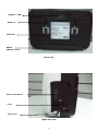
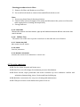
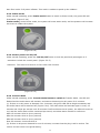
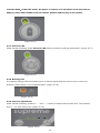
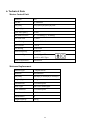
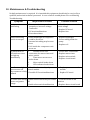
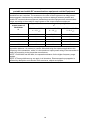
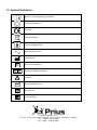
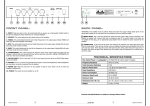
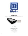
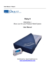
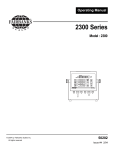
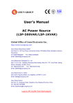
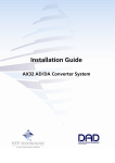
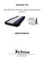
Supreme DX Alternating Anti-Decubitus Mattress Replacement System USER MANUAL Caremed Supply, Inc. 7F, No. 2, Lane 235, Bao Chiao Rd., Xin Tien City, Taipei 231 Taiwan Tel: +886-2-2917-9808 Fax: +886 -2-2918-6505 Warning * Connect the Master Control unit to a 220 ~240 volt to a power source. * Keep the pump and mattress away from open flame. * Keep the mattress away from sharp objects. * Do not place a heating device close to the mattress system. Caution * The Alternating System should always be used in accordance with your Institutions pressure care guidelines. * Re-positioning of the patient is always recommended when using an Alternating Pressure Air Mattress (APAM). * The Control unit can only be repaired by an authorized technician. * Do not drop the control unit. * Operation Temp: 15°C ~ 40°C R.H. : 30% ~ 75 % 1 Contents 1. The Purpose of this Manual P. 1 2. Intended Use P. 1 3. Hardware Introduction P. 1 4. Pre-application System Preparation P. 5 5. Operation instruction P. 7 6. Technical specification P. 11 7. Cleaning P. 12 8. Storage and Transportation P. 13 9. Waste Disposal P. 13 10. Maintenance and Trouble Shooting P. 14 11. EMC Related Notifications P. 15 12. Symbol Definition P. 19 2 1. The Purpose of this Manual This operation manual is mainly focused on the set up, cleaning and routine maintenance of the Supreme DX Alternating Pressure Mattress Replacement System. We recommend you keep this manual in a safe place, so that it may be referred to when required. 2. Intended use The Supreme DX Alternating Pressure Mattress Replacement System is primarily used for the treatment and prevention of decubitus ulcers up to stage IV. The System comprises of the latest technology in alternating mattress therapy which enables the mattress overlay to perform accurate pressure setting to individual patients needs. The cells of the mattress are spatially oriented above a two inch convoluted foam base to provide extra protection and comfort to the patient. Supreme DX Mattress Replacement System is one of the most advanced active pressure area management systems. . 3. Hardware introduction Control panel Air outlet plate Label area Power Cord Front view 3 Handle + Filter Hook set Label set Shock absorber foam Back view Power On/Off Switch Fuses Power Cord Right side view 4 Sensor connection Air outlet Left side view 4. Pre-application System Preparation: 4.1 Control Panel User could press the button on the control panel to operate the function. 4.1.1 Air Outlet Plate Connect the mattress to the control unit by plug in the air tube set (mattress side) to the air outlet plate (control unit side). Make sure the plug is connected properly. 4.1.2 Label Area Place for label (company logo label or simple operation label) 4.1.3 Power Cord Plug in the control unit and turn on the switch. ※ CAUTION: Make sure the voltage is AC 220 ~ 240 Volt. 4.1.4 Filter Device The Air Filter should be cleaned and checked as often as possible at a minimum of every six months. Air Filter can be removed and pulling outward from the back of the control unit. 5 Cleaning procedure for air filter: 1. Remove Air filter and Replace a new Filter. 2. Use a soft bristle brush to remove dust and difficult dried-on soil. Note: 1. Do not use phenol based cleaning solutions. 2. Switch off the electrical supply to the pump and disconnect the power cord from the main supply before cleaning and inspection) 3. Storage and care. 4.1.5 Hook Set Remove the control unit from the box, pop-up the fixation hooks and affix the unit at the foot end of the bed. Rubber Foot The rubber foot enable user to put the control unit on the table and avoid vibration. 4.1.6 4.1.7 Power On/Off Main power On/off switch. 4.1.8 Fuse Fuse for protection 4.1.9 Sensor connector Connect the sensor from mattress to control unit. 4.2 Overlay mattress 4.2.1 Use for either hospital and home cares 4.2.2 One Piece air cells design for maximum pressure distribution. 4.2.3 Ultra stretch, vapor permeable and water resistant top cover enhances comfort and minimizes hammocking, shear, friction and heat building up. 4.2.4 Modular construction for easy care cleaning and maintenance. 4.2.5 CPR quick release could deflate the system in 10 sec. 6 5. Operation instruction 5.1 Installation 1. Unpack the system and place the pump at the foot end of the bed. 2. Remove the existing mattress and place the support surface directly onto the bed frame with the vapor permeable cover uppermost, ensuring that the inflation tubes are also at the foot end of the bed. 3. Connect the air hoses from the mattress to the CPC connector on the side of the pump. 4. Turn the pump unit on. 5. The pump indicators will illuminate. The pump will begin inflating the air mattress. 6. Set the required pressure of the system by simply turning the pressure dial until the arrow on the dial is pointing at the required pressure setting. 7. Before repositioning the patient, wait 5 minutes after the low pressure LED has gone out. Moving the patient just after the LED goes out may activate the alarm. Note : The inflation time should not exceed 25 minutes. 5.2 Contol unit (pump) Alternate/Static mode switch Flower mode switch Transfer mode switch Alarm LED Pressure setting range Pressure setting buton (softer) Pressure setting button (harder) Alarm On/Off switch Control panel Lock On/Off Auto Firm mode switch Power On/Stand-By switch 7 5.2.1 Power On/Stand-By mode Plug the power cord to the socket and switch on the power at the power air outlet, the Orange LED will illuminate, it means Stand-by, please see below figure (Figure 5.2.1.1). Press the button Power On/Stand-By button, the LED light will turn to green, and the control unit will start to operate. (Figure 5.2.1.1) (Figure 5.2.2) 5.2.2 Alternate/Static mode Select the Alternate/Static mode by pressing Alternate/Static button. The Alternate green LED will illuminate when selected Alternate mode which shown as below (Figure 5.2.2.1). The Static green LED will illuminate when selected Static mode which shown as below (Figure 5.2.2.2). Alternate mode: A cell and B cell will take turn to inflate and deflate. Static mode: All cells are remaining the same level and static status. Alternate (Figure 5.2.2.1) Static (Figure 5.2.2.2) 5.2.3 Auto Firm mode When the pump is operation, press the Auto Firm button to switch to Auto Firm mode,the green LED will illuminated. (Figure 5.2.3) (Figure 5.2.3) 8 Auto Firm mode: Full power inflation. This mode is unable to speed up the inflation. 5.2.4 Fowler mode Under normal operating, press Fowler mode button to switch to fowler mode, the green LED will illuminated. (Figure 5.2.4) Fowler mode:Under Fowler mode, the system will enter static mode, and the pressure will increase two levels to inflate the system. (Figure 5.2.4) 5.2.5 Control panel Lock On/Off Under normal operating, press the Lock On/Off button to lock the panel and press again in 5 seconds to unlock the control panel. (Figure 5.2.5) Attention:The Auto Firm function is free under lock function. (Figure 5.2.5) 5.2.6 Transfer Mode Under normal operating, press Transfer Mode button to switch to Transfer Mode,the LED will flashed and the audio alarm will activate, and start to detecting the AC power for 2 minutes. (1) If there is no AC power is detected over 2 minutes, the green LED will be bright constantly and the audio alarm will be switched off (Figure 5.2.6). The audio alarm will activate again in every 15 minutes and 3 bips per second until 55 minutes if still not detect the AC power, the LED will turned to red, and the audio alarm will be continues bips sound, see below alarm sounds for reference: After 15 minutes: Bi bi bi (every second) After 30 minutes: Bi bi bi (every second) After 45 minutes: Bi bi bi (every second) Over 55 minutes: Continues Bi bi bi (2) If there is AC power detected for over 2 minutes, it means that the plug is still in socket. The control unit will return to original setting. 9 Transfer Mode:Under this mode, the power of control unit will switch from AC power to battery power which enables user to transfer patient without plug in the socket. (Figure 3.6.1) 5.2.7 Alarm On/Off Under normal operating, press Alarm On/Off button to switch on/off the audio alarm. (Figure 5.2.7) (Figure 5.2.7) 5.2.8 Warning LED The Warning orange LED illuminated to give a warning signal that the control unit is under Low pressure, power failure or out of bed situation. (Figure 5.2.8) (Figure 5.2.8) 5.2.9 Pressure adjustment Under normal operating, pressure “ - ” and “ + ” button to adjust soft and firm level. The pressure level 1 - 5 is from soft to firm (Figure 5.2.9). (Figure 5.2.9) 10 6. Technical Data Master Control Unit Model No. M12 Part No. FC-PHE0002 Size (mm) 345(L)x125(W)x225(H) mm Weight (Kg) 4 kg Cycle Time (min) 12 min Min/Max Pressure 16 ~ 32 mmHg +/- 6 mmHg Max Flow-rate 7 L/min Rated Voltage AC 100~240 volt Max Current 0.125 A Fuse Rating T1AH 250V Rated Frequency 50/60 Hz Protection Type Class II, Type BF Not AP or APG Type Mode of Operation Continuous Mattress Replacement Mattress type 8” Replacement Model No FM-PHE0005 Size (mm) 200cm(L) x 90cm(W) x 20cm(H) Weight (Kg) 8.8 Kg Cells Material PU coated Nylon Cover Type Full Cover with zipper Cover Material PU coated Nylon Base Material PVC Mesh Cells Number 20 Weight capacity 230 kg 11 7. Cleaning Mattress Overlay The mattress should be cleaned on the bed weekly using a damp soft cloth and mild detergent. If top sheet (Top cover) or base (Bottom cover) becomes grossly soiled, put on clean gloves, plastic gown and eye protection before removing top sheet or base and disposing according to standard hospital procedures for contaminated waste. Replace with clean covers. Covers can be washed and thermally disinfected in a washing machine following below procedure: (Never use phenol based cleaning solutions) Industrial Domestic Break washes Main washes Main washes Extraction 3 Cold Rinses Extraction Pre-wash Main Wash Extraction Cold Rinses Extraction Cold 60∘C 70∘C Cold 70∘C 10 minutes 6 minutes 10 minutes 2 minutes 5 minutes 10 minutes 2 minutes 5 minutes Article I. Mattress Cells can be wiped over with a solution of sodium hypochlorite 1000ppm or any other non-phenolic germicidal solution. Master Control Unit SWITCH OFF THE ELECTRICAL SUPPLY TO THE PUMP AND DISCONNECT THE POWER CORD FROM THE MAIN SUPPLY BEFORE CLEANING AND INSPECTION The pump unit should also be cleaned weekly using a damp soft cloth and mild detergent. The pump casing is manufactured from ABS plastic and if the case is soiled the pump can be wiped down with a sodium hypochlorite solution to dilution of 1000ppm or any EPA- approved hospital grade disinfectant. (Do not use phenol based cleaning solution) 12 8. Storage and Transportation Master Control Unit Storage and transportation conditions Temperature limitations: 5°C ~ 60°C Relative humidity: 30% ~ 75% Check the power cord and plug for abrasions or excessive wear. Plug in the unit and verify air flows from the units hose connection ports Place in plastic bag for storage. Overlay Mattress Check the air manifold for kinks or breaks. Replace if necessary. Twist the CPR plug at the head of the mattress and disconnect the air feed tubes. All the air will now be expelled. Starting at the head end, the mattress can now be rolled. Use the base mounted straps for containment. Place in plastic bag of storage. It is recommended the following guidelines are used whenever this system is being stored or transported another location: Temperature limitations: 10∘C ~ 40∘C Relative Humidity: 30% ~ 75% 9. Waste Disposal This Product has been supplied from an environmentally aware manufacturer that complies with the WEEE. This product may contain substances that could be harmful to the environment if disposed of in places (landfills) that are not appropriate according the legislation. Please be environmentally responsible and recycle this product through your recycling facility at its end of life. 13 10. Maintenance & Troubleshooting No daily maintenance is required. It is intended this equipment should only be serviced by a qualified, authorized technical personnel. In case of minor trouble please refer as following Troubleshooting. Symptom Inspection Procedure Possible Solution Pump not functioning 1. Power terminal may not be secured properly or incorrect voltage connected. 2. PC board malfunctions. 3. Fuses burn down 1. Check for power terminal or main voltage 2. Replace PC board 3. Replace fuse Pump functioning but no air out put 1. Bello diaphragm in compressor could be worn out. 2. Internal air tubing may become loose 3. Coil inside the compressor unit worn out 1. Replace diaphragm 2. Secure tubing inside the pump 3. Replace coil No Alternation or LED indicator does not light up immediately. 1. Possible loose wire connection for motor timer and micro switch. 2. Time motor worn out or broke down. 3. Micro switch broke down 4. LED indicator broke down 1. Secure wire connections. 2. Replace motor timer 3. Replace micro switch 4. Replace circuit board Low Pressure light 1. Check for functionality of pressure 1. Replace pressure control does not turn off control module. module after mattress is fully 2. Possible PC board malfunctions. 2. Replace PC board. inflated No audio alert during 1. Audio alarm switch may be turned 1. Turn the switch to ON power cut/power off. position. outage. 2. Audio alarm switch malfunction 2. Replace alarm circuit board 14 11. EMC related notifications Guidance and manufacturer’s declaration – electromagnetic emissions The Equipment is intended for use in the electromagnetic environment specified below. The customer or the user of the Equipment should assure that it is used in such an environment. Emissions test RF emissions Compliance Electromagnetic environment – guidance Group 1 The Equipment uses RF energy only for its internal function. Therefore, its RF emissions are very low and are not likely to cause any interference in nearby electronic equipment. Class B The Equipment is suitable for use in all establishments, including domestic establishments and those directly connected to the public lowvoltage power supply network that supplies buildings used for domestic purposes. CISPR 11 RF emissions CISPR 11 Harmonic emissions Class A IEC 61000-3-2 Voltage fluctuations/ Complies flicker emissions IEC 61000-3-3 15 Guidance and manufacturer’s declaration – electromagnetic immunity The Equipment is intended for use in the electromagnetic environment specified below. The customer or the user of the Equipment should assure that it is used in such an environment. Immunity test Electrostatic discharge (ESD) IEC 61000-4-2 IEC 60601 test level Compliance level 6 kV contact 6 kV contact 8 kV air 8 kV air Electrical fast transient/burst 2 kV for power supply lines 2 kV for power supply lines IEC 61000-4-4 1 kV for input/output lines 1 kV for input/output lines Surge IEC 61000-4-5 1 kV line(s) to line(s) 1 kV line(s) to line(s) 2 kV line(s) to earth 2 kV line(s) to earth <5 % UT (>95 % dip in UT) <5 % UT (>95 % dip in UT) for 0,5 cycle for 0,5 cycle 40 % UT (60 % dip in UT) 40 % UT (60 % dip in UT) for 5 cycles for 5 cycles 70 % UT (30 % dip in UT) 70 % UT (30 % dip in UT) for 25 cycles for 25 cycles <5 % UT (>95 % dip in UT) for 5 sec <5 % UT (>95 % dip in UT) for 5 sec interruptions and voltage variations on power supply input lines IEC 61000-4-11 Power frequency (50/60 Hz) magnetic field 3 A/m 3 A/m IEC 61000-4-8 Electromagnetic environment – guidance Floors should be wood, concrete or ceramic tile. If floors are covered with synthetic material, the relative humidity should be at least 30 %. Mains power quality should be that of a typical commercial or hospital environment. Mains power quality should be that of a typical commercial or hospital environment. Mains power quality should be that of a typical commercial or hospital environment. If the user of the Equipment] requires continued operation during power mains interruptions, it is recommended that the Equipment be powered from an uninterruptible power supply or a battery. Power frequency magnetic fields should be at levels characteristic of a typical location in a typical commercial or hospital environment. NOTE UT is the a.c. mains voltage prior to application of the test level. Guidance and manufacturer’s declaration – electromagnetic immunity 16 The Equipment is intended for use in the electromagnetic environment specified below. The customer or the user of the Equipment should assure that it is used in such an environment. IEC 60601 test Compliance Electromagnetic environment – Immunity test level guidance level Portable and mobile RF communications equipment should be used no closer to any part of the Equipment, including cables, than the recommended separation distance calculated from the equation applicable to the frequency of the transmitter. Conducted RF 3 Vrms Recommended separation distance 3 Vrms IEC 61000-4-6 150 kHz to 80 MHz d = 1,2 Radiated RF IEC 61000-4-3 3 V/m 80 MHz to 2,5 GHz 3 V/m d = 1,2 80 MHz to 800 MHz d = 2,3 800 MHz to 2,5 GHz where P is the maximum output power rating of the transmitter in watts (W) according to the transmitter manufacturer and d is the recommended separation distance in metres (m). Field strengths from fixed RF transmitters, as determined by an electromagnetic site survey,a should be less than the compliance level in each frequency range.b Interference may occur in the vicinity of equipment marked with the following symbol: NOTE 1 At 80 MHz and 800 MHz, the higher frequency range applies. NOTE 2 These guidelines may not apply in all situations. Electromagnetic propagation is affected by absorption and reflection from structures, objects and people. a Field strengths from fixed transmitters, such as base stations for radio (cellular/cordless) telephones and land mobile radios, amateur radio, AM and FM radio broadcast and TV broadcast cannot be predicted theoretically with accuracy. To assess the electromagnetic environment due to fixed RF transmitters, an electromagnetic site survey should be considered. If the measured field strength in the location in which the Equipment is used exceeds the applicable RF compliance level above, the Equipment should be observed to verify normal operation. If abnormal performance is observed, additional measures may be necessary, such as reorienting or relocating the Equipment. b Over the frequency range 150 kHz to 80 MHz, field strengths should be less than 3 V/m. 17 Recommended separation distances between portable and mobile RF communications equipment and the Equipment The Equipment is intended for use in an electromagnetic environment in which radiated RF disturbances are controlled. The customer or the user of the Equipment can help prevent electromagnetic interference by maintaining a minimum distance between portable and mobile RF communications equipment (transmitters) and the Equipment as recommended below, according to the maximum output power of the communications equipment. Rated maximum output power of transmitter W Separation distance according to frequency of transmitter m 150 kHz to 80 MHz d = 1,2 80 MHz to 800 MHz d = 1,2 800 MHz to 2,5 GHz d = 2,3 0,01 0,12 0,12 0,23 0,1 0,38 0,38 0,73 1 1,2 1,2 2,3 10 3,8 3,8 7,3 100 12 12 23 For transmitters rated at a maximum output power not listed above, the recommended separation distance d in metres (m) can be estimated using the equation applicable to the frequency of the transmitter, where P is the maximum output power rating of the transmitter in watts (W) according to the transmitter manufacturer. NOTE 1 At 80 MHz and 800 MHz, the separation distance for the higher frequency range applies. NOTE 2 These guidelines may not apply in all situations. Electromagnetic propagation is affected by absorption and reflection from structures, objects and people. 18 12. Symbol Definition Refer to Accompanying Documents Class II Equipment CE Mark Waste Disposal Type BF Applied Part Alternating Current Manufacture Reference Number Authorized Representative Caution Date of Manufacture Batch Code Serial Number Caremed Supply, Inc. 7F, No. 2, Lane 235, Bao Chiao Rd., Xin Tien City, Taipei 231 Taiwan Tel: +886-2-2917-9808 Fax: +886 -2-2918-6505 19