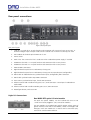
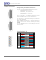
1
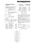
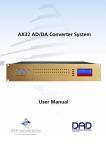
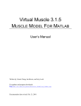
Installation Guide
AX32 AD/DA Converter System
Installation Guide AX32
IMPORTANT SAFETY INSTRUCTIONS
READ AND KEEP THESE INSTRUCTIONS
WARNING – when using electric products, basic precautions should be followed, including the following:
Read all of the safety and installations instructions and explanation of graphic symbols before using the
product.
1. Do not use this apparatus near water.
2. Clean only with dry cloth.
3. Do not block any ventilation openings. Install in
accordance with the manufacturer's instructions.
4. Do not install near any heat sources such as
radiators, heat registers, stoves, or other
apparatus (including amplifiers) that produce
heat.
5. Do not defeat the safety purpose of the polarized
or grounding-110 to 125V type plug according to
UL 817 and CSA C22.2 no. 42. A polarized plug
has two blades with one wider than the other. A
grounding type plug has two blades and a third
grounding prong. The wide blade or the third
prong are provided for your safety. If the
provided plug does not fit into your outlet,
consult an electrician for replacement of the
obsolete outlet.
6. Protect the power cord from being walked on or
pinched particularly at plugs, convenience
receptacles, and the point where they exit from
the apparatus.
7. Only use attachments/accessories specified by
the manufacturer.
8. Use only with the cart, stand, tripod, bracket, or
table specified by the manufacturer, or sold with
the apparatus. When a cart is used, use caution
when moving the cart/apparatus combination to
avoid injury from tip-over.
9. Unplug this apparatus during lightning storms or
when unused for long periods of time.
10. Refer all servicing to qualified service personnel.
Servicing is required when the apparatus has
been damaged in any way, such as power-supply
cord or plug is damaged, liquid has been spilled
or objects have fallen into the apparatus, the
apparatus has been exposed to rain or moisture,
does not operate normally, or has been dropped.
DANGER
Improper connection of the equipment-grounding can result in a risk of electric shock. Do not modify
the plug provided with the product – if it will not fit the outlet have a proper outlet installed by a
qualified electrician. Do not use an adapter which defeats the function of the equipment-grounding
conductor. If you are in doubt as to whether the product is properly grounded, check with a qualified
serviceman or electrician.
Doc no. AX32-8001-A-4
Rev. date 140107
Page 2 of 15
Installation Guide AX32
The product must be grounded. If it should malfunction or breakdown, grounding provides a path of
least resistance for electric current to reduce the risk of electric shock. This product is equipped with a
power supply cord having an equipment-grounding conductor and a grounding plug. The plug must
be plugged into an appropriate outlet which is properly installed and grounded in accordance with all
local codes and ordinances.
WARNING
• This product, either alone or in combination with an amplifier and speakers or headphones, may be
capable of producing sound levels that could cause permanent hearing loss. Do not operate at a high
volume level or at a level that is uncomfortable. If you experience any hearing loss or ringing in the
ears, you should consult an audiologist.
•
The product should be located so that its location or position does not interfere with its proper
ventilation.
•
The power-supply cord of the product should be unplugged from the outlet when left unused for a
long period of time. When unplugging the power supply, do not pull on the cord, but grasp it by the
plug.
•
Care should be taken so that objects do not fall and liquids are not spilled into the enclosure through
openings.
SERVICE
• Do not attempt to service the product beyond that described in the user maintenance instructions. All
other servicing should be referred to qualified service personnel.
•
The product should be serviced by qualified service personnel when:
1.
2.
3.
4.
The power supply cord or plug has been damaged, or
Objects have fallen, or liquid has spilled into the product, or
The product has been exposed to rain, or
The product does not appear to be operating normally or exhibits a marked change in
performance, or
5. The product has been dropped, or the enclosure damaged.
WARNING – Hazardous moving parts inside the unit. Keep fingers and other body parts away.
Doc no. AX32-8001-A-4
Rev. date 140107
Page 3 of 15
Installation Guide AX32
Contents
GENERAL DESCRIPTION.
5
Accessing the AX 32 cards.
5
BEFORE YOU START
5
Mechanical installation and low fan noise
5
Network configuration
5
CONTROL SOFTWARE INSTALLATION
Computer recommendation
6
6
Program installation
6
Assigning the IP address for the computer and the AX32
6
OPERATION
8
Front panel LED’s
8
Front panel status display
9
Reconfig button
10
REAR PANEL CONNECTIONS.
11
Digital I/O Connections
11
Analogue I/O Connections
13
SPECIFICATIONS
14
Audio Specifications
14
Electrical Specifications:
15
Mechanical specifications
15
Environmental specifications.
15
© 2014 All rights reserved. DAD - Digital Audio Denmark is a registered
Trademark of NTP Technology A/S, who is the legal owner of the brand.
Product features and specifications are subject to change without notice.
NTP Technology A/S shall not be liable for technical or editorial errors contained herein, nor for incidental or
consequential damages resulting from the furnishing, performance or use of this manual.
Company Address: NTP Technology A/S, Nybrovej 99, DK-2820 Gentofte, Denmark
Fax. +45 44 53 11 70, E-mail: [email protected], Web: www.digitalaudio.dk.
All trademarks are recognized as the property of their respective owners.
Doc No. AX32-8001-A-4 rev.1
Doc no. AX32-8001-A-4
Rev. date 140110
Page 4 of 15
Installation Guide AX32
General description.
Congratulations, and thank you for purchasing the DAD AX32 Converter System. AX32 is an extremely
capable multi channel audio converter and microphone preamplifier for independent simultaneous analogto-digital (A/D), and digital-to-analog (D/A) conversion as well as digital-to-digital (D/D) format conversion
and signal routing. The AX32 has as standard 8 stereo AES3 inputs and outputs (16 I/O channels), dual
DigiLink™ interface for 64 input and output channels to Pro Tools™ HDX and one coaxial 64-channel MADI
input and output connection. The AX32 can be fitted with up to 6 pcs. 8-channel A/D or 8-channel D/A
cards, providing for up to 48 analogue input or output channels. Digital interface options include up to 2
optical MADI 64-channel input and output connections and a 64-channel IP Audio interface power by
Dante™. The AX32 is equipped with one power supply, except when configured with 6 analogue cards in
which case a second power supply is installed. It is also possible to add a the second power supply as a
redundant power supply when less than 6 cards are installed.
This installation guide provides basic information about the installation and use of the AX32. For
more detailed information please refer to the AX32 user manual available on the DAD website,
www.digitalaudio.dk.
Accessing the AX 32 cards.
It is not necessary to open the AX32 during installation, unless you need to add extra A/D or D/A cards.
The AX32 cards and module options can be accessed by removing the lid of the AX32 chassis. The chassis
provides 8 card slot positions, where six can be used for analogue cards. It is important that the placement
of the cards are maintained since they correspond to the configuration of the unit. The mini I/O module and
the IP Audio option are mounted on the Main board of the converter. Cards and modules should not be
removed or changed without consulting either NTP Technology or an authorised DAD representative.
Before you start
Place your AX32 on a hard and dry surface or mount it into a 19” rack, and leave plenty of room for
ventilation.
In order to meet the EMC requirements of directives EN 55103 and FCC 47 CFR part 15, and in order to
obtain the highest performance of the AX32, you must use good quality correctly shielded cables for all
external connections when installing the AX32. For the power connection, a normal unshielded power cable
with a proper protective earth conductor can be used.
Make sure that your sound system is at a safe volume level.
Mechanical installation and low fan noise
The AX32 is fitted with two ultra-quiet fans to ensure optimum operating temperature. The fans are
temperature-controlled, i.e. the rotation speed, and thereby noise, is dependent on the temperature inside
the AX32. The fans are hardly audible during normal operation, assuming the AX32 is installed correctly.
The optimal air flow is from the front holes in the bottom of the unit to the rear holes in the rear and top
plate. When the unit is installed, considerations have to be made to ensure proper air circulation from the
bottom to the rear. It is recommended to leave 1RU of space free under the AX32 and not to block the rear
panel and top plate holes. The speed of the two low noise fans will be increased automatically to keep the
internal temperature low if there is insufficient airflow. If the internal temperature exceeds 60ºC / 140ºF a
temperature alarm will appear in the display.
Please refer to the mechanical specifications section for more details regarding the installation.
Network configuration
AX32 is equipped with two GigaBit Ethernet connectors and internally an Ethernet switch, a controller part
and a part for the optional IP Audio option powered by Dante™. The network connectors can operate as
Doc no. AX32-8001-A-4
Rev. date 140110
Page 5 of 15
Installation Guide AX32
two “parallel” connectors for the internal switch, or as dual connectors for redundant IP audio operation. In
this case controlling the unit is done via Net port 1. AX32 has one to tree different IP addresses. One for the
unit control via DADman and one or two for the IP audio in respectively single or redundant mode. The
network configuration is managed separately for the controlling interface and for the IP audio interface,
and can have different configuration. The controlling interface is used for controlling AX32 from DADman
and the IP audio interface (one or two if installed) is used for interfacing IP audio in a network. The factory
default setting of the IP address of the controller port of the AX32 is 10.0.7.20. The IP address can be
changed manually via DADman or it can be set to be automatically assigned by a DHCP server/router in the
network. If needed AX32 can be set in recovery mode with a the fixed factory defined IP address 10.0.7.20
and IP discovery via DHCP. This is described in the Reconfig section of this manual. For a more detailed
description of the network functionality, configuration, and behaviour please refer to the separate AX32
user manual.
Control software installation
Computer recommendation
The DADman control program operates on any Windows or MAC-OSX based computer, and is constantly
maintained for interoperability with the latest OS versions.
Program installation
This section will take you through the installation procedure for the DADman computer control program.
The AX32 is controlled from a PC or MAC using a network connection. The PC/MAC and the AX32 units
must be connected on the same subnet.
The DADman remote control program
1. Install the DADman program by downloading the application from www.digitalaudio.dk. Follow the
instructions of the install program. Please note that there are two different program downloads;
One for Windows and one for MAC-OSX.
2. Create a shortcut for the DADman program on the desktop.
3. Double-click on the DADman icon and start the DADman application.
4. Connect one (only one) AX32 to the network
5. In the top menu bar select Tools/Device List and apply ‘Refresh’ when using a Windows PC, in order
to discover the AX32 on the network. On MAC-OSX ‘Action’ is used to select ‘Refresh IP list’ The
Device List window for Windows and MAC-OSX is show in figure 1.
Assigning the IP address for the computer and the AX32
When the DADman program is installed you are able to finalise the network configuration of the AX32 by
connecting AX32 one by one. You have the option of using fixed IP addresses or IP addresses assigned via
DHCP.
Fixed IP address
You must have a preferred range of IP addresses, and a network mask for the computer network and the
connected AX32 units.
1. Configure your computer IP address and network mask via the computer control panel to e.g.
10.0.7.25 | 255.255.255.0
2. Select the AX32 in the DADman Settings/ Device List menu by right clicking the unit line and select
‘Network settings’ when using a Windows PC. On MAC-OSX you use the ‘Action’ button to select
‘Network Settings’.
3. Configure via DADman each AX32 in turn with a unique IP address and the preferred network
mask e.g. 10.0.7.21 | 255.255.255.0. In this window you can also configure the IP audio network
settings
Doc no. AX32-8001-A-4
Rev. date 140110
Page 6 of 15
Installation Guide AX32
4. When you are done you can connect more than one AX32 to the network, and they will appear in
the DADman Device List.
Automatic IP address
You must have a network with a DHCP server which will allocate the IP addresses.
1. Configure your computer IP address via the computer control panel to DHCP.
2. Select the AX32 in the DADman Tools / Device List menu by right clicking the unit line and select
‘Network settings’.
3. Configure via DADman each AX32 in turn to DCHP.
4. When you are done you can connect more than one AX32 to the network, and they will appear in
the DADman Device List.
Figure 1, DADman Device list in Windows
Figure 2, DADman Device list in MAC-OSX
Doc no. AX32-8001-A-4
Rev. date 140110
Page 7 of 15
Installation Guide AX32
For a more detailed description of the DADman software please refer to the AX32 user manual
available on the DAD website, www.digitalaudio.dk
Note. In order to have proper function of the AX32 the router and sample rate configuration has
to be set correctly via DADman.
Operation
The AX32 is controlled via the DADman software and some simple control and status viewing can be made
via the front panel of the unit. The DADman control program interfaces to the unit via one of the rear panel
Ethernet connectors. On the front panel two rows of LED indicators are available for indication of the AD
and DA signal level, an LCD display is available for simple control and for showing various settings of the
AX32. 4 buttons are available for accessing the settings shown in the display.
Figure 3, Front panel layout
Front panel layout
1.
16 LED indicators for signal level indication of the analogue AD input.
2.
16 LED indicators for signal level indication of the analogue DA output.
3.
4 buttons for operating the status display.
4.
Status display.
Front panel LED’s
AX32 has two rows of 16 LED indicators on the front panel showing the signal status for the AD inputs and
DA outputs.
Doc no. AX32-8001-A-4
AD
OL/signal
Signal of AD channel 1-16. Yellow indicates
signal input above -42dB FS, and red indicates
signal above -0.5 dB FS.
DA
Signal/carrier
Signal of DA channel 1-16. Yellow indicates
signal input above -42dB FS, and green
indicates signal below -42dB FS and a valid
digital input source/carrier.
Rev. date 140110
Page 8 of 15
Installation Guide AX32
Front panel status display
The display of the AX32 has four rows for displaying information and four knobs for entering and scrolling
information. The display can show more pages and each page can consist of rows where settings can be
changed, and with rows for just showing status information. The display functions for the basic page are
described below. More pages are available depending on the firmware version of the AX32. For more
information on these pages please refer to the user manual.
Operating buttons
Setting
Pushing the button scrolls trough the settings
rows. The > curser marks the selected
row/function.
Up
Pushing the button scrolls up the value/ setting
of the selected function.
Down
Pushing the button scrolls down
value/setting of the selected function.
Page
Pushing the button scrolls trough the available
display pages.
the
Basic display page – sample rate, synchronization, ID
and alarms
Sample Rate
Shows sample rate of the AX32. If an asterisk
* is shown the sample rate is controlled via an
external digital audio interface.
SRate Adapt
Shows which external digital audio interface
that controls the sample rate or shows
“Intern” for internal sample rate control.
Sync Source
Shows the external synchronisation clock
source or shows “Intern” when the AX32 uses
the internal clock.
Unit ID /Name
Shows unit ID number and unit name. This is
set via DADman.
Alarm/status
Shows alarm status:
Sync OK = Clock sync is OK
SyncErr = Clock sync failure
TempErr = temperature inside AX32 is above
60ºC / 140ºF. Check that the AX32 is installed
in accordance with the instructions.
Fan Err = One of the two fans is not working
correctly. Contact a DAD representative or the
factory.
CardErr = Fault in one of the A/D or D/A
cards. Contact a DAD representative or the
factory.
Psu Err = Power supply failure. Contact a DAD
representative or the factory.
Doc no. AX32-8001-A-4
Rev. date 140110
Page 9 of 15
Installation Guide AX32
Reconfig button
The “Reconfig” button on the back of the AX32 should not be used during normal installation. It is
generally intended as an ultimate recovery function in case something goes wrong during programming of
IP addresses or a software upgrade, e.g. an unintended power loss. It allows the AX32 to start in various
“basic” modes so it can be restored without having to be returned to the factory.
The “Reconfig” button is accessed via a hole in the rear panel using a pen or a similar pointed item. A green
LED is visible through the hole. When the “Reconfig” button is activated, the LED will light up indicating the
two reconfig modes of the AX32.
Recovery mode
“Reconfig”
pushed while the
unit is powering
up
Green LED
turns ON
The AX32 enters a recovery mode. In this mode
only a basic boot software is operative in the
unit, and new software can be downloaded via
the DADman software. This mode is used if the
software in the AX32 for some reason is not
operative or broken.
The IP address settings of the unit are the last
setting used in the unit.
“Reconfig”
short push
while the unit is
in reconfig mode
and Green LED is
on
The AX32 remains in reconfig mode as described
above.
The IP address settings of the unit is however set
to DHCP. In case there is no DHCP server on the
network, the AX32 will default to IP address
10.0.7.20 / 255.255.0.0 after approx. 2 minutes.
Green LED
turns OFF
The selection of either of the two recovery modes are fixed after selection. The AX32 will start with a basic
boot software and IP configuration. The AX32 will not be operational until a proper firmware has been
downloaded via the DADman software and it has been restarted. By enabling recovery mode with default IP
address and network configuration the unit can always be identified on a network via the default setup.
Note that the IP address referred to is the IP address of the controller/management
interface of the unit. This is not the IP address of the IP audio interface if a such is
installed. This IP address can not be accessed in recovery or restore defaults mode.
Restore defaults
Push “Reconfig”
for 10 sec. while
the unit is in
normal operation.
Release
“Reconfig”
button
Green LED
OFF
Doc no. AX32-8001-A-4
The AX32 enters a restore default mode. In this
mode all setting of the unit is initialized to the
factory programmed defaults.
The IP address settings of the unit are remain
unchanged and do NOT return to factory default.
When the “Reconfig” button is released the
firmware of the unit restarts with the factory
default settings and enter normal operation
automatically.
Rev. date 140110
Page 10 of 15
Installation Guide AX32
Rear panel connections.
Figure 4, Rear panel layout
Rear panel layout
1. Card slot 1 to card slot 8. 25 pole female D-sub connector with Tascam pin-out. Up to 6 pcs. 8channel analogue input or output cards can be installed. Slots 2 and 6 are currently not used.
2. Mini module slot for dual optical MADI I/O via SFP.
3. Power switch.
4. Mains inlet. The same mains inlet is used even when a redundant power supply is installed.
5. AES/EBU I/O channels 1-4. 25 pole female D-sub connector with Tascam pin-out.
6. AES/EBU I/O channels 5-8. 25 pole female D-sub connector with Tascam pin-out.
7. MADI I/O BNC connectors.
8. DigiLink™interface port for Pro Tools™HDX, Primary port.
9. DigiLink™interface port for Pro Tools™HDX, Primary port or Expansion port (configurable).
10. Word Clock or Video Black Burst synchronization input (configurable), BNC connector.
11. Word Clock synchronization output BNC connector.
12. AES11/AES3 synchronization input, female XLR connector.
13. Ethernet control and IP audio Primary port (net 1) RJ45 connector. Control port in redundant IP
audio mode.
14. Ethernet control and IP audio Secondary port (net 2) RJ45 connector
15. Reconfigure button, and status LED
Digital I/O Connections
Dual MADI SFP optical I/O mini-module
The Dual SFP optical module, can be installed with one or two
“Small form-factor pluggable” (SFP) transceiver modules.
The SFP modules are standard types which support various types of
optical interfaces with LED or Laser diodes, various wavelengths and
fibertypes. Each SFP module has a receiver and a transmitter part,
and can be used for MADI audio I/O.
Doc no. AX32-8001-A-4
Rev. date 140110
Page 11 of 15
Installation Guide AX32
The right part of the SFP connector is the receiver and the left part is
the transmitter.
AES11 Sync input, Female XLR connector
Pin 1.
TX. +
Pin 2.
TX. –
Pin 3.
RX. +
Ethernet, RJ45 connector, Gigabit
Pin 1.
BI_DA+
Pin 2.
BI_DA-
Pin 3.
BI_DB+
Pin 4.
BI_DC+
Pin 5.
BI_DC-
Pin 6.
BI_DB-
Pin 7.
BI_DD+
Pin 8.
BI_DD-
AES/EBU I/O 25 pole female D-sub connectors
The top connector provides the connection for AES/EBU I/O
channels 1-4. The lower connector provides the connection for
AES/EBU I/O channels 5-8, providing a total of 8 AES/EBU I/O
channels.
Below is listed the connections for the combined input and output
25 pole D-sub connector. The pinning is according to the
proprietary standard by the company Tascam.
Connections channel 1-4 / channel 5-8
Pin out
Doc no. AX32-8001-A-4
Pin no
Func.
Pin no
Func.
1
DOUT 4/8 +
14
DOUT 4/8 -
2
GND
15
DOUT 3/7 +
3
DOUT 3/7 -
16
GND
4
DOUT 2/6 +
17
DOUT 2/6 -
5
GND
18
DOUT 1/5 +
6
DOUT 1/5 -
19
GND
7
DIN 4/8 +
20
DIN 4/8 -
8
GND
21
DIN 3/7 +
9
DIN 3/7 -
22
GND
10
DIN 2/6 +
23
DIN 2/6 -
11
GND
24
DIN 1/5 +
12
DIN 1/5-
25
GND
13
N.C.
Rev. date 140110
Page 12 of 15
Installation Guide AX32
Analogue I/O Connections
Analogue I/O 25 pole female D-sub connectors.
There are three types of optional analogue card for the AX32:
•
CARD-AX32-L8, 8 ch. Line AD Card
•
CARD-AX32-M8, 8 ch. Mic/Line AD Card
•
CARD-AX32-DA8, 8 ch. Line DA Card
These are interfaced via a 25 pole D-sub connectors on the card
which is accessible from the rear panel of the AX32 chassis.
This connector type is used both for the analogue input card and for
the analogue output card.
Below is listed the connection for the 25 pole D-sub connector. The
pinning is according to the proprietary standard by the company
Tascam.
For more a detailed description of the two cards please refer to the
AX32 user manual.
Connections channel 1-8
Pin out
Doc no. AX32-8001-A-4
Pin no
Func.
Pin no
Func.
1
AIN/OUT 8 +
14
AIN/OUT 8 -
2
GND
15
A/IN/OUT 7 +
3
AIN/OUT 7 -
16
GND
4
AIN/OUT 6 +
17
AIN/OUT 6 -
5
GND
18
AIN/OUT 5 +
6
AIN/OUT 5 -
19
GND
7
AIN/OUT 4 +
20
AIN/OUT 4 -
8
GND
21
AIN/OUT 3 +
9
AIN/OUT 3 -
22
GND
10
AIN/OUT 2 +
23
AIN/OUT 2 -
11
GND
24
AIN/OUT 1 +
12
AIN/OUT 1-
25
GND
13
N.C.
Rev. date 140110
Page 13 of 15
Installation Guide AX32
Specifications
Audio Specifications
Analogue input
Sampling, resolution
5bit sigma/[email protected] or 6.144 MHz, 24 bit PCM
PCM (DXD) sample rates
44,1, 48, 88.2, 96, 174.4, 192, 352.8, 384 kHz
DSD sample rates
2.8224 & 5.6448 Mhz (64 & 128 fs)
Dynamic range (A)
> 123 dB
THD+N(A)
< -117 dB@-3dB FS / 0,00014%
Cross talk
< -120 dB
Input Impedance (differential)
> 10 k Ohm
Max input level
Adjustable from 9 dBu to 30 dBu in steps of 0.1 dB
Microphone input gain range/accuracy
Adjustable from -18 to +70 dB, in steps of 0.1 dB,
± 0.25 dB accuracy
Microphone equivalent input noise (A)
< -133dB
Analogue output
Modulator resolution, format
32 x oversampling, 1 bit DSD, 24 bit PCM
PCM (DXD) sample rates
44,1, 48, 88.2, 96, 174.4, 192, 352.8, 384 kHz
DSD sample rates
2.8224 & 5.6448 Mhz (64 & 128 fs)
Dynamic range (A)
> 128 dB
THD+N(A)
< -110 dB@-3dB FS / 0,00031%
Cross talk
< 120 dB
Max output level
Adjustable from -60 dBu to 24 dBu in steps of 0.1 dB
Digital I/O and Synchronisation
Digital I/O formats/ Supported sample rate
AES/EBU, Pro Tools™ DigiLink™, Dante™ IP Audio/up
to 192 kHz.MADI / up to 384 kHz and DSD
Synchronisation/sample rate
AES11, Word Clock, All digital inputs, Video Sync
(word clock connector)/ PAL, NTSC, SECAM
Network Interface
Interface
Doc no. AX32-8001-A-4
1000BASE-T, RJ45 connector, 4-pair connection
Rev. date 140110
Page 14 of 15
Installation Guide AX32
Electrical Specifications:
Power consumption
90 VA max.
Input voltage
90 – 260 VAC
100 – 240 VAC Nominal, 47 - 63 Hz
Mains fuse, mounted in IEC connector
1 A, T1AH/250V
Safety compliance
EN 60950-1:2006
Power supply cord must be min. light sheathed flexible cord according to IEC60227 (designation 60227 IEC
52) and include a protective earth conductor having a green-and-yellow insulation. Cross-sectional areas
min. 3x0.75mm2”
Mains line plug type
Correct type acc. to standard
110-125V
UL817 and CSA C22.2 no 42
220-230V
CEE 7 page VII, SR section 107-2-D1/IEC 83
page C4.
240V
BS 1363 of 1984.Specification for 13A fused
plugs and switched and unswitched socket
outlets
Mechanical specifications
Chassis standard
19”, 2 RU
Chassis depth, without connectors mounted
35.0 cm / 13.8”
Chassis body width
43.5 cm / 17.2”
Weight, not including I/O cards
5 kg / 11 lbs.
Chassis air flow from front to rear
Environmental specifications.
Operating Temperature
0 – 45 ºC / 32 - 113ºF
Humidity
EMC compliance
EN 55103-1, part 1: emission
EN 55103-2, part 2: Immunity
FCC 47 CFR part 15 (B): emission
Doc no. AX32-8001-A-4
Rev. date 140110
Page 15 of 15