1
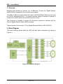
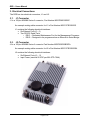
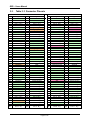
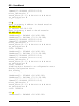
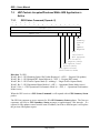
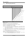
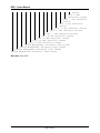
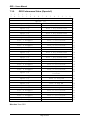
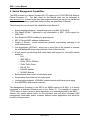
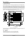
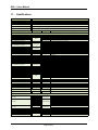
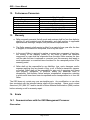
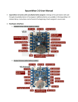
Gigabit Ethernet Switch (GES)
User’s Manual
1775 West Hibiscus Blvd, Suite 200
Melbourne, FL 32901
(321) 984-1671
www.Aeronix.com
GES – Users Manual
Document Revision History
Ver/Rev
Description of Change
Chg’d By
Chg/Rel #
Date
-001/-
Initial Release of User’s Manual for the
GEN2GES
R. Little
SP-619
10 October 2011
-001/A
Added Section 12 – Performance Parameters
R. Kneapler
SP-640
9 December 2011
-001/B
Update Section 9 to reflect updated mounting
hardware
R. Kneapler
SP-705
2 July 2012
-001/C
Fixed word order issue with Summary Status
packet in (Sect 7.3.2), and corrected the unit
weight on pages 29 & 31
R. Little
SP-725
6 September 2012
-001/D
Added COG dimensioning to GES Chassis
Drawing in Section 9.
S. Ammerman
SP-738
19 October 2012
-001/E
Updated Qualification Test Table (see page
30)
S. Ammerman
SP-814
16 September 2013
Note:
This manual applies to the Aeronix
AE101264-002
12-Port Gigabit Ethernet Switch
This User’s Manual is Part Number AE301016-001
Page ii
GES – Users Manual
Table of Contents
1.
OVERVIEW .......................................................................................................... 1
2.
BLOCK DIAGRAM ............................................................................................... 1
3.
ELECTRICAL CONNECTIONS ............................................................................ 2
3.1. J1 CONNECTOR ................................................................................................... 2
3.2. J2 CONNECTOR ................................................................................................... 2
3.3. TABLE 3-1: CONNECTOR PIN-OUTS ....................................................................... 3
3.4. INTERFACE PORT DETAILS .................................................................................... 4
3.4.1. Ethernet Ports ............................................................................................ 4
3.4.2. Serial and Programming Ports ................................................................... 4
3.4.3. Management Processor ............................................................................. 4
3.4.4. Input Power ................................................................................................ 5
4.
PORT DETAILS.................................................................................................... 6
4.1.
4.2.
ETHERNET PORT MAPPING ................................................................................... 6
SERIAL PORTS..................................................................................................... 6
5.
BOOTLOADER .................................................................................................... 7
6.
MENU INTERFACE .............................................................................................. 8
6.1. REQUIRED HARDWARE ......................................................................................... 8
6.2. SERIAL PORT SETUP ............................................................................................ 8
6.3. MENUS ............................................................................................................... 8
6.3.1. How the menus work.................................................................................. 8
6.3.2. Menu Header ............................................................................................. 8
6.3.3. Main Menu ................................................................................................. 9
6.3.4. Configuration Menu .................................................................................. 10
6.4. EXAMPLE .......................................................................................................... 12
7.
MANAGEMENT PROCESSOR ETHERNET COMMUNICATIONS ................... 15
7.1. NETWORK COMMUNICATIONS SUPPORTED........................................................... 15
7.2. GENERAL FORMAT OF A GES UDP PACKET ........................................................ 15
7.3. UDP PACKETS ACCEPTED/PRODUCED W HILE GES APPLICATION IS ACTIVE .......... 16
7.3.1. GES Status Command (Opcode: 0) ......................................................... 16
7.3.2. GES Summary Status (Opcode 1) ........................................................... 17
7.3.3. GES Initiated BIT Status (Opcode 2) ....................................................... 18
7.3.4. GES Operational Status (Opcode 4) ........................................................ 20
7.3.5. GES Performance Status (Opcode 5) ...................................................... 21
7.3.6. GES Programming Command (Opcode 3) ............................................... 22
7.3.7. GES Programming Response (Opcode 6) ............................................... 23
7.3.8. GES Reboot ............................................................................................. 24
7.3.9. GES Reboot Acknowledge ....................................................................... 24
7.3.10. Opcode Unrecognized By Application ...................................................... 24
Page iii
GES – Users Manual
7.4. UDP PACKETS ACCEPTED/PRODUCED W HILE BOOTLOADER IS ACTIVE ................. 24
7.4.1. Opcode Unrecognized By Bootloader ...................................................... 24
7.4.2. Erase Non-Boot-Bank (NBB) Flash .......................................................... 25
7.4.3. Erase NBB Flash Acknowledge ............................................................... 25
7.4.4. Erase NBB Flash Completed ................................................................... 25
7.4.5. Program NBB Data .................................................................................. 26
7.4.6. Program NBB Data Acknowledge ............................................................ 26
7.4.7. Program NBB Data Completed ................................................................ 26
7.4.8. Finished Programming ............................................................................. 27
7.4.9. Finished Programming Acknowledge ....................................................... 27
7.4.10. Bad CRC .................................................................................................. 27
8.
SWITCH MANAGEMENT CAPABILITIES ......................................................... 28
9.
HARDWARE MOUNTING .................................................................................. 29
10.
INDICATORS ..................................................................................................... 29
11.
QUALIFICATIONS ............................................................................................. 30
12.
PERFORMANCE PARAMETERS ...................................................................... 31
13.
WARRANTY ....................................................................................................... 31
14.
ERRATA ............................................................................................................. 31
14.1. COMMUNICATIONS WITH THE GES MANAGEMENT PROCESSOR ............................. 31
15.
PRODUCTS AND SERVICES ............................................................................ 33
Aeronix places no restriction on the duplication or distribution of this document;
however, it must remain unaltered and in its entirety.
Copyright 2012© by Aeronix, Inc. All rights reserved.
Page iv
GES – Users Manual
1. Overview
Designed and produced by Aeronix, Inc. of Melbourne, Florida, the Gigabit Ethernet
Switch (GES) is designed for use in hostile environments.
The GES is a lightly managed switch with twelve 10/100/1000BaseT Ethernet ports, and
two RS-232 management ports. Its rugged monolithic design is intended to operate in
severe environments without the need for forced air cooling.
This document is intended to provide the information required to interface with the
Aeronix Gigabit Ethernet Switch (GES) hardware.
The part number of the Aeronix 12-Port Gigabit Ethernet Switch is AE101264-002.
2. Block Diagram
The basic functional blocks within the GES and their basic interactions are shown in
Figure 2-1.
Figure 2-1: GES Block Diagram
Page 1 of 33
GES – Users Manual
3. Electrical Connections
The GES has two electrical connectors, J1 and J2.
3.1.
J1 Connector
J1 is a 100 pin M38999 Series II connector, Part Number MS27508E22B35P.
An example mating cable connector for J1 is Part Number MS27473E22B35S.
J1 contains the following electrical interfaces:
• Six Ethernet Ports (0 – 5)
• Two RS-232 Serial Ports
o DEV1 – Dedicated Maintenance Port for the Management Processor
o DEV2 – Designed to be programmed as an Ethernet to Serial Bridge
3.2.
J2 Connector
J2 is a 100 pin M38999 Series II connector Part Number MS27508E22B35PA.
An example mating cable connector for J2 is Part Number MS27473E22B35SA.
J2 contains the following electrical interfaces:
• Six Ethernet Ports (6 – 11)
• Input Power (nominal 28 VDC per MIL-STD-704A)
Page 2 of 33
GES – Users Manual
3.3.
Table 3-1: Connector Pin-outs
J1
Pin
1
2
3
4
5
6
7
8
9
10
11
12
13
14
15
16
17
18
19
20
21
22
23
24
25
26
27
28
29
30
31
32
33
34
35
36
37
38
39
40
41
42
43
44
45
46
47
48
49
50
Signal
Chassis Ground
Port 0 - A(+)
Port 0 - C(-)
Port 0 - D(+)
Port 0 - D(-)
Chassis Ground
Port 1 - A(+)
Chassis Ground
Chassis Ground
Port 0 - A(-)
Port 0 - C(+)
Chassis Ground
Port 1 - A(-)
Port 1 - C(+)
Port 1 - D(-)
Reserved
Chassis Ground
Chassis Ground
Port 0 - B(+)
Chassis Ground
Port 1 - B(+)
Port 1 - B(-)
Port 1 - C(-)
Port 1 - D(+)
Reserved
GND
Reserved
Port 0 - B(-)
Chassis Ground
Chassis Ground
Chassis Ground
Chassis Ground
Chassis Ground
Chassis Ground
Reserved
Reserved
Chassis Ground
Chassis Ground
Chassis Ground
Port 2 - A(+)
Chassis Ground
Port 3 - B(+)
Port 3 - B(-)
Port 3 - C(-)
Port 3 - D(+)
Reserved
GND
Chassis Ground
Port 2 - B(-)
Port 2 - A(-)
Pin
51
52
53
54
55
56
57
58
59
60
61
62
63
64
65
66
67
68
69
70
71
72
73
74
75
76
77
78
79
80
81
82
83
84
85
86
87
88
89
90
91
92
93
94
95
96
97
98
99
100
J2
Signal
Chassis Ground
Chassis Ground
Port 3 - A(+)
Port 3 - C(+)
Port 3 - D(-)
RX_FROM_DEV1
TX_TO_DEV1
Chassis Ground
Port 2 - B(+)
Port 2 - C(-)
Port 2 - D(+)
Chassis Ground
Port 3 - A(-)
Chassis Ground
Chassis Ground
Chassis Ground
RX_FROM_DEV2
TX_TO_DEV2
Chassis Ground
Chassis Ground
Port 2 - C(+)
Port 2 - D(-)
Chassis Ground
Chassis Ground
Port 5 - D(-)
Port 5 - D(+)
GND
Chassis Ground
Port 4 - A(+)
Chassis Ground
Chassis Ground
Chassis Ground
Port 5 - A(+)
Port 5 - C(+)
Port 5 - C(-)
Chassis Ground
Chassis Ground
Port 4 - A(-)
Port 4 - D(-)
Port 4 - D(+)
Chassis Ground
Port 5 - A(-)
Port 5 - B(+)
Chassis Ground
Port 4 - B(+)
Port 4 - B(-)
Port 4 - C(+)
Port 4 - C(-)
Chassis Ground
Port 5 - B(-)
Pin
1
2
3
4
5
6
7
8
9
10
11
12
13
14
15
16
17
18
19
20
21
22
23
24
25
26
27
28
29
30
31
32
33
34
35
36
37
38
39
40
41
42
43
44
45
46
47
48
49
50
Page 3 of 33
Signal
Chassis Ground
Port 6 - A(+)
Port 6 - C(-)
Port 6 - D(+)
Port 6 - D(-)
Chassis Ground
Port 7 - A(+)
Chassis Ground
Chassis Ground
Port 6 - A(-)
Port 6 - C(+)
Chassis Ground
Port 7 - A(-)
Port 7 - C(+)
Port 7 - D(-)
28V
Chassis Ground
Chassis Ground
Port 6 - B(+)
Chassis Ground
Port 7 - B(+)
Port 7 - B(-)
Port 7 - C(-)
Port 7 - D(+)
28V
Reserved
Chassis Ground
Port 6 - B(-)
Chassis Ground
Chassis Ground
Chassis Ground
Chassis Ground
Chassis Ground
Chassis Ground
28V
28V
Chassis Ground
Chassis Ground
Chassis Ground
Port 8 - A(+)
Chassis Ground
Port 9 - B(+)
Port 9 - B(-)
Port 9 - C(-)
Port 9 - D(+)
Reserved
Reserved
Chassis Ground
Port 8 - B(-)
Port 8 - A(-)
Pin
51
52
53
54
55
56
57
58
59
60
61
62
63
64
65
66
67
68
69
70
71
72
73
74
75
76
77
78
79
80
81
82
83
84
85
86
87
88
89
90
91
92
93
94
95
96
97
98
99
100
Signal
Chassis Ground
Chassis Ground
Port 9 - A(+)
Port 9 - C(+)
Port 9 - D(-)
28VRTN
28VRTN
Chassis Ground
Port 8 - B(+)
Port 8 - C(-)
Port 8 - D(+)
Chassis Ground
Port 9 - A(-)
Chassis Ground
Chassis Ground
Chassis Ground
28VRTN
Reserved
Chassis Ground
Chassis Ground
Port 8 - C(+)
Port 8 - D(-)
Chassis Ground
Chassis Ground
Port 11 - D(-)
Port 11 - D(+)
28VRTN
Chassis Ground
Port 10 - A(+)
Chassis Ground
Chassis Ground
Chassis Ground
Port 11 - A(+)
Port 11 - C(+)
Port 11 - C(-)
Chassis Ground
Chassis Ground
Port 10 - A(-)
Port 10 - D(-)
Port 10 - D(+)
Chassis Ground
Port 11 - A(-)
Port 11 - B(+)
Chassis Ground
Port 10 - B(+)
Port 10 - B(-)
Port 10 - C(+)
Port 10 - C(-)
Chassis Ground
Port 11 - B(-)
GES – Users Manual
3.4.
Interface Port Details
3.4.1.
Ethernet Ports
All connections in Table 3-1 that have a white background are Ethernet Port
connections.
Table 3-2 indicates the appropriate wiring connections for the GES Ethernet ports
relative to the available link speeds. Please note that MDI is the preferred connection
choice. The GES and most modern Ethernet enabled electronics are capable of
connecting using the MDIX scheme, but it is not advised.
Table 3-2: Ethernet Port Connections
GES Pin
RJ-45
Pinout P/N
Port X - A(+/-)
Port X - B(+/-)
Port X - C(+/-)
Port X - D(+/-)
1/2
3/6
4/5
7/8
3.4.2.
MDI
MDIX
1000Base-T
100Base-T
10-Base-T
1000Base-T
100Base-T
10-Base-T
BI_DA+BI_DB+BI_DC+BI_DD+-
TX+RX+Unused
Unused
TX+RX+Unused
Unused
BI_DA+BI_DB+BI_DC+BI_DD+-
RX+TX+Unused
Unused
RX+TX+Unused
Unused
Serial and Programming Ports
All connections in Table 3-1 that have an Orange background are Serial Port
connections.
The DEV1 serial port is a dedicated GES Management Processor Maintenance Port.
The DEV2 serial port was designed for future expansion as an in-band Ethernet to Serial
Bridge.
Table 3-3 indicates the appropriate wiring connections for the DEV1 and DEV2 serial
ports.
Table 3-3: Serial Port Connections
3.4.3.
Signal
Direction
Type
Connects
Notes
TX_TO_DEVX
RX_FROM_DEVX
GND
Output
Input
Reference
RS-232
RS-232
RTN
DB9-2
DB9-3
DB9-5
J1-26,77
Management Processor
The GES provides an ARM 9 processor running at 96MHz for both internal and customer
specified functions. This processor is in-band allowing control by any device on the
Ethernet network that is connected to the GES.
This processor is lightly loaded after initialization of the GES allowing customer specified
functions to use most of the available processing power if required.
Page 4 of 33
GES – Users Manual
The primary purpose of this processor is to:
• Initialize the Ethernet Switch IC for GES default operation
• PBIT and CBIT
• Customer specific functions if required
3.4.4.
Input Power
The connections shown in Table 3-1 with a Red background are Power Connections.
The input power requirements are as specified in MIL-STD-704A:
Aircraft, 28 VDC, Category B (curves 2 &3 of Fig. 9)
During normal operations the average power consumption with all 12 ports connected at
1 GB speed is 17 watts. Input current is internally limited to 2 amps.
Page 5 of 33
GES – Users Manual
4. Port Details
4.1.
Ethernet Port Mapping
In its factory default configuration, all twelve Ethernet ports of the GES are configured
identically. When programming custom configurations into the GES, the External-Port
numbers map to the Switch’s MAC and Phy Port numbers as defined in Table 4-1.
Table 4-1 Ethernet Port Mapping
4.2.
External Port
MAC Port
Phy Port
Port 0
Port 1
Port 2
Port 3
Port 4
Port 5
Port 6
Port 7
Port 8
Port 9
Port 10
Port 11
GES Internal
10
11
9
8
7
6
4
2
3
5
1
0
4
5
6
7
8
9
10
11
12
13
14
15
Management CPU
CPU Port
n/a
Serial Ports
There are two serial ports associated with the Management Processor, DEV1 and DEV2.
Both ports are RS-232 compatible and operate only at:
• 115.2K baud
• 1 Stop Bit
• No Parity
• No Flow Control
The DEV1 port supports out-of-band configuration management of the GES.
The DEV2 serial port is available for customer specific uses. Contact Aeronix if you
would like custom programming for this port such as an Ethernet to Serial bridge or
sensor/actuator to Ethernet. See section 6.2 for current details.
Page 6 of 33
GES – Users Manual
5. Bootloader
The GES management processor (STR912) executes code directly from flash. The GES
supports running from either of two internal banks of flash. The smaller bank is
dedicated to the bootloader. This allows upgrading of the GES application software in
the field over the network. Immediately after power up the bootloader allows nine
seconds to begin a code load before it jumps to the application that executes out of the
main (larger) bank of flash.
Page 7 of 33
GES – Users Manual
6. Menu Interface
The GES Menu Interface is used for out-of-band control of the GES. It provides the
ability to customize configurations and status monitoring.
6.1.
Required Hardware
6.2.
Serial Port Setup
To interact with the STR9 CPU, the following hardware is required:
• Power supply
• Gigabit Ethernet Switch, Part Number AE101264
• Computer with Terminal Emulation software (i.e.: TeraTerm under Windows)
Serial port setup is 115,200 Baud with N81 and no hardware or software handshaking.
The command system is tied to DEV1.
The second UART (DEV2) will reply to an input character with a message string “Saw a
NN on port 1\n”, where NN is a hexadecimal representation of the input character.
6.3.
Menus
6.3.1.
How the menus work
6.3.2.
Menu Header
All menu selections require a single character to be input. There is no need to enter a
carriage return.
GES Software Version: 4.3
GES Bootloader Version: 7
Hardware Serial Number: 1002
MAC Address: 00:0B:D1:08:10:02
FDB Table Index: 984
IP Address[0]: 192.168.1.100
IP Mask[0]
: 255.255.255.0
IP Address[1]: 172.31.129.100
IP Mask[1]
: 255.255.255.0
Temperature: 35 C
The menu header is displayed above every menu. The serial number, MAC address and
FDB table index are unique to each GES (these values are programmed at the factory
and are not modifiable by the customer). The IP addresses and netmasks are
configurable by the customer via the RS-232 interface.
Page 8 of 33
GES – Users Manual
6.3.3.
Main Menu
Main menu
d
u
1
2
o
c
display statistics
display UIP statistics
MAC port status
PHY port status
dump MIB counts
go to configuration menu
6.3.3.1.
‘d’ – display statistics
6.3.3.2.
‘u’ – display UIP statistics
6.3.3.3.
‘1’ – MAC port status
6.3.3.4.
‘2’ – PHY port status
6.3.3.5.
‘o’ – dump MIB counts
6.3.3.6.
‘c’ – go to configuration menu
Display the counts of interrupts serviced by the management processor.
Display the packet counts of various types that were sent and received by the
management processor.
Show the port status of the MAC ports. Shows link connection status, speed, duplex and
other information. Note: Port 63 corresponds to the management CPU port.
Show the port status of the phy ports. Shows link up/down, speed, duplex, and other
information gleaned from the phy chips connected to each external port.
Show the various packet and octet counts for data going into and out of every port. In
addition counts going to and from the CPU port are shown.
Change to the Configuration Menu (you can get back to the main menu by hitting ‘b’).
Page 9 of 33
GES – Users Manual
6.3.4.
Configuration Menu
6.3.4.1.
Menu Overview
Configuration menu
c
p
s
d
m
u
f
b
6.3.4.2.
show configuration
set primary IP address and netmask
set secondary IP address and netmask
set mirror destination
set port mirror details
set cpu mirror details
write out current config to flash
back to main menu
‘c’ – show configuration
Display the contents of the configuration structure (Displayed below is the default
configuration). This configuration is stored in flash memory and may be modified using
the serial port and saved. This configuration survives power cycling of the GES unit.
IP_address[0]: 6401A8C0 (192.168.1.100)
IP_address[1]: 64811FAC (172.31.129.100)
IP_mask[0]: 00FFFFFF (255.255.255.0)
IP_mask[1]: 00FFFFFF (255.255.255.0)
mirror_destination: 2
switch_mirror[0..11]: N B N N N N N N N N N N
cpu_switch_mirror: N
crc32: 3875E0CC
The management CPU supports two IP addresses. This allows the GES management
CPU to potentially participate in two distinct subnets. The primary IP and net mask are
shown as IP_address[0] and IP_mask[0]. The secondary IP and net mask are shown
as IP_address[1] and IP_mask[1].
The GES supports port mirroring. This allows monitoring of traffic going in or out of any
of the ports. The mirror_destination is the external port number where the mirrored
traffic is directed. The switch_mirror[0..11] describes the mirroring state of each
external port of the GES. An ‘N’ indicates no mirroring, an ‘I’ indicates ingress mirroring,
an ‘E’ indicates egress mirroring, while a ‘B’ indicates both ingress and egress mirroring.
The cpu_switch_mirror is much like the switch_mirror[0..11], but it indicates the
mirroring for data going to and from the CPU port.
NOTE: Port mirroring is enabled using a GES Status Command UDP packet with the
GES Traffic Capture Mode bit set. Once enabled, the mirroring can only be reset with a
power cycle of the GES.
Page 10 of 33
GES – Users Manual
The crc32 is generated internally and is used to verify the stored values in flash. If the
crc32 fails the GES reverts to the default values.
6.3.4.3.
‘p’ – set primary IP address and netmask
6.3.4.4.
‘s’ – set secondary IP address and netmask
6.3.4.5.
‘d’ – set mirror destination
6.3.4.6.
‘m’ – set mirror details
6.3.4.7.
‘u’ – set cpu mirror details
6.3.4.8.
‘f’ – write out current config to flash
6.3.4.9.
‘b’ – back to main menu
The GES will prompt for the new IP address (saved as IP_address[0]). It expects it in
dotted notation followed by a carriage return. Any characters other than 0-9, a period or
a carriage return cause the update to be aborted. After the IP address is entered, the
GES prompts for the netmask (saved as IP_mask[0]). The netmask must also be
entered in dotted notation. At the conclusion of a successful IP address and netmask
input the GES writes the configuration to flash.
The GES will prompt for the new IP address (saved as IP_address[1]). It expects it in
dotted notation followed by a carriage return. Any characters other than 0-9, a period or
a carriage return cause the update to be aborted. After the IP address is entered, the
GES prompts for the netmask (saved as IP_mask[1]). The netmask must also be
entered in dotted notation. At the conclusion of a successful IP address and netmask
input the GES writes the configuration to flash.
The GES prompts for an entry (0-9,a,b), where external ports 10 and 11 are represented
by ‘a’ and ‘b’ respectively. At the conclusion of a successful mirror destination input the
GES writes the configuration to flash.
The GES prompts for each port in sequence, expecting ‘I’ (for ingress),’E’ (for egress),’N’
(neither ingress nor egress),’B’ (both ingress and egress).
This updates the
switch_mirror[0..11] field. At the conclusion of a successful mirror details input the
GES writes the configuration to flash.
The GES prompts for the management CPU mirroring configuration, expecting ‘I’ (for
ingress),’E’ (for egress),’N’ (neither ingress nor egress),’B’ (both ingress and egress). At
the conclusion of a successful CPU mirror details input the GES writes the configuration
to flash.
Commands the GES to write out the current configuration to flash. This is useful if you
want to burn the default configuration to flash. Normally any update of any of the
configuration fields causes the configuration to be saved to flash.
Return to the main menu.
Page 11 of 33
GES – Users Manual
6.4.
Example
This is an example of the interaction with the GES command line interface.
The following actions are performed:
• Change to the configuration menu
• Show the current extra configuration
• Update the Primary IP
• Show the new configuration
Note: characters input by the user are in bold.
Main Menu
Cmd
d
u
1
2
o
c
Description
display statistics
display UIP statistics
MAC port status
PHY port status
dump MIB counts
go to configuration menu
GES>c
GES Software Version: 4.3
GES Bootloader Version: 7
Hardware Serial Number: 1002
MAC Address: 00:0B:D1:08:10:02
FDB Table Index: 984
IP Address[0]: 192.168.1.100
IP Mask
[0]: 255.255.255.0
IP Address[1]: 172.31.129.100
IP Mask
[1]: 255.255.255.0
temperature: 43 C
Configuration Menu
Cmd
c
p
s
d
m
u
f
b
Description
show configuration
set primary IP address and netmask
set secondary IP address and netmask
set mirror destination
set port mirror details
set cpu mirror details
write out current config to flash
back to main menu
GES>c
IP_address[0]: 6401A8C0 (192.168.1.100)
IP_address[1]: 64811FAC (172.31.129.100)
Page 12 of 33
GES – Users Manual
IP_mask[0]: 00FFFFFF (255.255.255.0)
IP_mask[1]: 00FFFFFF (255.255.255.0)
mirror_destination: 2
switch_mirror[0..11]: N B N N N N N N N N N N
cpu_switch_mirror: N
crc32: 3875E0CC
GES>p
Enter in primary IP address in dotted notation
192.168.1.101
you entered 192.168.1.101
Enter in primary IP mask in dotted notation
255.255.255.0
IP_address[0]: 6401A8C0 (192.168.1.100)
IP_address[1]: 64811FAC (172.31.129.100)
IP_mask[0]: 00FFFFFF (255.255.255.0)
IP_mask[1]: 00FFFFFF (255.255.255.0)
mirror_destination: 2
switch_mirror[0..11]: N B N N N N N N N N N N
cpu_switch_mirror: N
crc32: 3875E0CC
IP_address[0]: 6501A8C0 (192.168.1.101)
IP_address[1]: 64811FAC (172.31.129.100)
IP_mask[0]: 00FFFFFF (255.255.255.0)
IP_mask[1]: 00FFFFFF (255.255.255.0)
mirror_destination: 2
switch_mirror[0..11]: N B N N N N N N N N N N
cpu_switch_mirror: N
crc32: 3692081D
Disabling Write Protection on configuration sector
Erasing configuration sector
done erasing
Writing configuration structure
IP_address[0]: 6501A8C0 (192.168.1.101)
IP_address[1]: 64811FAC (172.31.129.100)
IP_mask[0]: 00FFFFFF (255.255.255.0)
IP_mask[1]: 00FFFFFF (255.255.255.0)
mirror_destination: 2
switch_mirror[0..11]: N B N N N N N N N N N N
cpu_switch_mirror: N
crc32: 3692081D
GES> c
IP_address[0]: 6401A8C0 (192.168.1.101)
Page 13 of 33
GES – Users Manual
IP_address[1]: 64811FAC (172.31.129.100)
IP_mask[0]: 00FFFFFF (255.255.255.0)
IP_mask[1]: 00FFFFFF (255.255.255.0)
mirror_destination: 2
switch_mirror[0..11]: N B N N N N N N N N N N
cpu_switch_mirror: N
crc32: 3692081D
Page 14 of 33
GES – Users Manual
7. Management Processor Ethernet Communications
7.1.
Network Communications Supported
7.2.
General Format of a GES UDP Packet
The GES management processor supports ARP, ICMP (ping), and UDP communications. UDP
traffic is supported on port 3500. All fields are sent in network byte order. This means that fields
larger than a byte will be read and written using standard access routines. These routines are
host-to-network-short “htons()”, host-to-network-long “htonl()”, network-to-host-short “ntohs()”
and network-to-host-long “ntohl()”.
1
1
1
5
4
3
Length (in
Opcode
Additional
1
1
2
1
words)
1
0
9
8
7
6
words (if required)
Length – Length of the GES UDP Packet in words.
Opcode – Operation performed by this packet.
Page 15 of 33
5
4
3
2
1
0
GES – Users Manual
7.3.
UDP Packets Accepted/Produced While GES Application is
Active
7.3.1.
1
5
1
4
GES Status Command (Opcode: 0)
1
3
1
2
1
1
1
0
9
8
7
6
Length (3)
Opcode (0)
Spare (0)
5
4
3
2
1
0
0
1
2
GES
Summary
Status
1Hz
Update
Request
GES
Initiated
BIT Request
GES Traffic
Capture Mode
GES Operational
Status Mode
GES Operational
Performance Mode
Direction: To GES.
Word 2, Bit 0 – GES Summary Status 1Hz Update Request (0 – OFF, 1 – Request 1Hz updates)
Word 2, Bit 1 – GES Initiated BIT Status Request (0 – OFF, 1 – Request IBIT status)
Word 2, Bit 2 – GES Traffic Capture Mode (0 – nothing, 1 – Begin Traffic Capture Mode)
Word 2, Bit 3 – GES Operational Status Mode (0 – OFF, 1 – Operational Status Mode Active)
Word 2, Bit 4 – GES Operational Performance Mode (0 – OFF, 1 – Operational Performance
Mode Active)
When the GES receives a GES Status Command it will respond with a GES Summary Status
packet.
The GES also supports up to two requests for 1Hz GES Summary Status updates. The first two
requestors will receive GES Summary Status messages at approximately 1Hz intervals. If a
request for 1Hz updates comes from the same IP address, but from a different port it will replace
the previous 1Hz update request.
Page 16 of 33
GES – Users Manual
7.3.2.
1
5
1
4
GES Summary Status (Opcode 1)
1
3
1
2
1
1
1
0
9
Spare (0)
GES Firmware Level
8
7
6
Length (4)
Opcode (1)
5
4
3
2
1
0
0
1
2
Overall
GES
Mngmnt
Processor
Status
Overall Phy
Status
Overall TDR
Status
Baseline Mode of
Operation
Updated Mode of
Operation
Traffic Monitor Function
Active
Operational Status Function
Active
Operational Performance Function
Active
GES Status Command Message Received
GES Software Level
3
Direction: From GES
GES Firmware Level – This is the revision level of the bootloader code.
GES Software Level – This is the revision level of the GES application code.
Word 2, Bit 0 – Overall GES Management Processor Status (0 – good, 1 – degraded)
Word 2, Bit 1 – Overall Phy Status (0 – good, 1 – degraded)
Word 2, Bit 2 – Overall TDR Status (0 – good, 1 – degraded)
Word 2, Bit 3 – Baseline Mode of Operation (0 – not in Baseline Mode, 1 – Baseline Mode). Baseline
mode of operation indicates that there are no configuration words applied to either of the two
internal switches by the configuration.
Word 2, Bit 4 – Updated Mode of Operation (0 – not in Updated Mode, 1 – Updated Mode). Updated
mode of operation indicates that at least one of the two internal switches has configuration words
applied.
Word 2, Bit 5 – Traffic Monitor Function Active (0 – not Active, 1 – Active). The traffic monitor function
is latched once enabled. A power cycle is required to reset.
Word 2, Bit 6 – Operational Status Function Active (0 – not Active, 1 – Active)
Word 2, Bit 7 – Operational Performance Function Active (0 – not Active, 1 – Active)
Word 2, Bit 8 – GES Status Command Message Received (0 – not received, 1 – received). This bit
indicates that a GES Status Command message was received by the GES.
Page 17 of 33
GES – Users Manual
7.3.3.
1
5
1
4
GES Initiated BIT Status (Opcode 2)
1
3
1
2
1
1
1
0
9
8
7
6
Length (5)
Opcode (2)
Spare (0)
5
4
3
2
1
0
0
1
2
Overall
GES
Mngmnt
Processor
Status
Overall Phy
Status
Overall TDR
Status
3
Port 0
PHY
Status
Port 1 PHY
Status
Port 2 PHY
Status
Port 3 PHY Status
Port 4 PHY Status
Port 5 PHY Status
Port 6 PHY Status
Port 7 PHY Status
Port 8 PHY Status
Port 9 PHY Status
Port 10 PHY Status
Port 11 PHY Status
Port A PHY Status
Port B PHY Status
Port C PHY Status
Port D PHY Status
4
Port 0
TDR
Interface
Status
Port 1 TDR
Interface
Page 18 of 33
GES – Users Manual
Status
Port 2 TDR
Interface Status
Port 3 TDR Interface
Status
Port 4 TDR Interface
Status
Port 5 TDR Interface Status
Port 6 TDR Interface Status
Port 7 TDR Interface Status
Port 8 TDR Interface Status
Port 9 TDR Interface Status
Port 10 TDR Interface Status
Port 11 TDR Interface Status
Switch Management Processor ID#1 Status
Switch Management Processor ID#2 Status
Switch Management Processor ID#3 Status
Switch Management Processor ID#4 Status
Direction: From GES
Page 19 of 33
GES – Users Manual
7.3.4.
1
5
1
4
GES Operational Status (Opcode 4)
1
3
1
2
1
1
Spare (0)
1
0
9
8
7
6
Length (5)
Opcode (4)
5
4
3
2
1
0
0
1
2
Port 0
Duplex
Setting
Port 1 Duplex
Setting
Port 2 Duplex
Setting
Port 3 Duplex Setting
Port 4 Duplex Setting
Port 5 Duplex Setting
Port 6 Duplex Setting
Port 7 Duplex Setting
Port 8 Duplex Setting
Port 9 Duplex Setting
Port 10 Duplex Setting
Port 11 Duplex Setting
3
Port 0 Speed
Status
Port 1 Speed Status
Port 2 Speed Status
Port 3 Speed Status
Port 4 Speed Status
Port 5 Speed Status
Port 6 Speed Status
Port 7 Speed Status
Spare (0)
4
Port 8 Speed
Status
Port 9 Speed Status
Port 10 Speed Status
Port 11 Speed Status
Direction: From GES.
Page 20 of 33
GES – Users Manual
7.3.5.
1
5
1
4
GES Performance Status (Opcode 5)
1
3
1
2
1
1
1
0
9
8
7
6
5
4
3
2
1
Length (34)
Opcode (5)
Spare (0)
Port 0 Avg Bandwidth
Port 0 Dropped
Port 0 Collisions
Spare (0)
Port 1 Avg Bandwidth
Port 1 Dropped
Port 1 Collisions
Spare (0)
Port 2 Avg Bandwidth
Port 2 Dropped
Port 2 Collisions
Spare (0)
Port 3 Avg Bandwidth
Port 3 Dropped
Port 3 Collisions
Spare (0)
Port 4 Avg Bandwidth
Port 4 Dropped
Port 4 Collisions
Spare (0)
Port 5 Avg Bandwidth
Port 5 Dropped
Port 5 Collisions
Spare (0)
Port 6 Avg Bandwidth
Port 6 Dropped
Port 6 Collisions
Spare (0)
Port 7 Avg Bandwidth
Port 7 Dropped
Port 7 Collisions
Spare (0)
Port 8 Avg Bandwidth
Port 8 Dropped
Port 8 Collisions
Spare (0)
Port 9 Avg Bandwidth
Port 9 Dropped
Port 9 Collisions
Port 10 Avg Bandwidth
Spare (0)
Percent
Port 10 Dropped
Port 10 Collisions
Spare (0)
Port 11 Avg BW
Port 11 Dropped
Port 11 Collisions
Spare (0)
Port A Avg BW
Port A Dropped
Port A Collisions
Spare (0)
Port B Avg BW
Port B Dropped
Port B Collisions
Spare (0)
Port C Avg BW
Port C Dropped
Port C Collisions
Spare (0)
Port D Avg BW
Port D Dropped
Port D Collisions
Direction: From GES.
Page 21 of 33
0
0
1
2
3
4
5
6
7
8
9
10
11
12
13
14
15
16
17
18
19
20
21
20
21
20
21
20
21
20
21
20
21
20
21
GES – Users Manual
7.3.6.
1
5
1
4
P7
GES Programming Command (Opcode 3)
1
3
1
2
1
1
1
0
9
8
7
6
5
4
Length (93)
Opcode (3)
Spare (0)
Spare (0)
Spare (0)
CPU
P11
P10
P6
P5
P4
P3
P2
Primary IP Address (MSW)
Primary IP Address (LSW)
Primary Netmask (MSW)
Primary Netmask (LSW)
Secondary IP Address (MSW)
Secondary IP Address (LSW)
Secondary Netmask (MSW)
Secondary Netmask (LSW)
3
2
1
0
a
b
c
Mirror Dest
P9
P8
P1
P0
0
1
2
3
4
5
6
7
8
9
10
11
12
13
Direction: To GES.
Not yet supported.
This packet allows modification of the GES configuration stored in flash.
a – When set, this bit indicates that the Mirror Dest should be updated with the contents of this
packet.
b – When set, this bit indicates that the P0-P11 and CPU port mirroring details will be updated
with the contents of this packet.
c – When set, this bit indicates that the Network Parameters will be updated with the contents of
this packet (Primary IP & Netmask, as well as Secondary IP & Netmask).
Primary IP Address – The GES management processor’s primary IP address.
Primary Netmask – The GES management processor’s primary network mask.
Secondary IP Address – The GES management processor’s secondary IP address.
Secondary Netmask – The GES management processor’s secondary network mask.
Mirror dest – External port used as destination for data mirrored from other ports on this switch.
P0-P11, and CPU – Each port has two bits indicating the mirroring for the particular port.
00 – monitor no ingress or egress traffic.
01 – monitor ingress traffic only
10 – monitor egress traffic only
11 – monitor both ingress and egress traffic
Page 22 of 33
GES – Users Manual
7.3.7.
1
5
1
4
P7
GES Programming Response (Opcode 6)
1
3
1
2
1
1
1
0
9
8
7
6
5
4
Length (93)
Opcode (3)
Spare (0)
Spare (0)
Spare (0)
CPU
P11
P10
P6
P5
P4
P3
P2
Primary IP Address (MSW)
Primary IP Address (LSW)
Primary Netmask (MSW)
Primary Netmask (LSW)
Secondary IP Address (MSW)
Secondary IP Address (LSW)
Secondary Netmask (MSW)
Secondary Netmask (LSW)
3
2
1
0
a
b
c
Mirror Dest
P9
P8
P1
P0
0
1
2
3
4
5
6
7
8
9
10
11
12
13
Direction: From GES.
Not yet supported.
This packet is generated in response to a GES Programming Command (Opcode 3). By sending a
GES Programming Command (Opcode 3) with the ‘a’, ‘b’, and ‘c’ bits all reset, the current GES
configuration can be queried without effecting the current configuration.
a – always 0.
b – always 0.
c – always 0.
Primary IP Address – The GES management processor’s primary IP address.
Primary Netmask – The GES management processor’s primary network mask.
Secondary IP Address – The GES management processor’s secondary IP address.
Secondary Netmask – The GES management processor’s secondary network mask.
Mirror dest – External port used as destination for data mirrored from other ports on this switch.
P0-P11, and CPU – Each port has two bits indicating the mirroring for the particular port.
00 – monitor no ingress or egress traffic.
01 – monitor ingress traffic only
10 – monitor egress traffic only
11 – monitor both ingress and egress traffic
Page 23 of 33
GES – Users Manual
7.3.8.
1
5
GES Reboot
1
4
1
3
1
2
1
1
1
0
9
8
7
6
Length (2)
Opcode (102)
5
4
3
2
1
0
0
1
Direction: To GES.
GES software doesn’t support GES Reboot. In order to do a GES application update the unit
must be power cycled to cause the bootloader to listen for the UDP packets necessary to program
a new GES application into the 2048K flash bank.
7.3.9.
1
5
GES Reboot Acknowledge
1
4
1
3
1
2
1
1
1
0
9
8
7
6
Length (2)
Opcode (103)
5
4
3
2
1
0
0
1
Direction: From GES.
Version 3.0 software doesn’t support GES Reboot. In order to do a GES application update the
unit must be power cycled to cause the bootloader to listen for the UDP packets necessary to
program a new GES application into the 512K flash bank.
7.3.10.
1
5
1
4
Opcode Unrecognized By Application
1
3
1
2
1
1
1
0
9
8
7
6
Length (2)
Opcode (101)
5
4
3
2
1
0
0
1
Direction: From GES.
This opcode is generated by the GES when it receives
7.4.
UDP Packets Accepted/Produced While Bootloader is Active
7.4.1.
1
5
1
4
Opcode Unrecognized By Bootloader
1
3
1
2
1
1
1
0
9
8
7
6
Length (2)
Opcode (100)
5
4
3
2
1
0
0
1
Direction: From bootloader.
This opcode is generated by the GES while the bootloader is active and an opcode that the
bootloader doesn’t support is received.
Page 24 of 33
GES – Users Manual
7.4.2.
1
5
1
4
Erase Non-Boot-Bank (NBB) Flash
1
3
1
2
1
1
1
0
9
8
7
6
Length (2)
Opcode (104)
5
4
3
2
1
0
0
1
Direction: To bootloader.
This message halts the 9-second countdown and the boot process. It causes the bootloader to
immediately send back an Erase NBB Flash Acknowledge UDP message. Next the bootloader
erases the contents of the larger bank of flash (the Non-Boot Bank or NBB). After the GES
completes the erase, the bootloader sends an Erase NBB Flash Complete UDP message. This
last message indicates to the loader that it may begin sending Program NBB Data UDP
messages containing the contents of the new GES Application to program into the NBB flash.
7.4.3.
1
5
1
4
Erase NBB Flash Acknowledge
1
3
1
2
1
1
1
0
9
8
7
6
Length (2)
Opcode (105)
5
4
3
2
1
0
0
1
Direction: From bootloader.
This is the first GES response by the bootloader to an Erase NBB Flash UDP message. It lets the
loader know that the bootloader has received the message and the loader must wait for the Erase
NBB Flash Completed message before it can proceed. The erase procedure can take several
seconds.
7.4.4.
1
5
1
4
Erase NBB Flash Completed
1
3
1
2
1
1
1
0
9
8
7
6
Length (2)
Opcode (106)
5
4
3
2
1
0
0
1
Direction: From bootloader.
This is the second GES response by the bootloader to an Erase NBB Flash UDP message. It lets
the loader know that the bootloader has completely erased the NBB flash and the bootloader is
now ready to receive data to program into the NBB flash.
Page 25 of 33
GES – Users Manual
7.4.5.
1
5
1
4
Program NBB Data
1
3
1
2
1
1
1
0
9
8
Length (5
Opcode
Offset
Offset
7
6
5
to 516)
(107)
(MSW)
(LSW)
4
3
2
1
0
Data (1 to 512 words)
0
1
2
3
4 to
515
Direction: To bootloader.
The loader sends between 1 and 512 words at a time to the bootloader to program into the NBB
flash. The Offset is the byte offset into the NBB flash of the first data word of this packet. The
GES only supports writing words at a time so this offset should always be even.
7.4.6.
1
5
1
4
Program NBB Data Acknowledge
1
3
1
2
1
1
1
0
9
8
7
6
Length (2)
Opcode (108)
5
4
3
2
1
0
0
1
Direction: From bootloader.
The bootloader immediately responds with this message when the bootloader receives a Program
NBB Data UDP message. The bootloader then writes the data words to NBB flash. Next the
bootloader sends a Program NBB Data Completed UDP message to indicate to the loader that
another data packet may be sent.
7.4.7.
1
5
1
4
Program NBB Data Completed
1
3
1
2
1
1
1
0
9
8
7
6
Length (2)
Opcode (109)
5
4
3
2
1
0
Direction: From bootloader.
This packet is sent by the bootloader once the data has been written to the NBB flash.
Page 26 of 33
0
1
GES – Users Manual
7.4.8.
1
5
1
4
Finished Programming
1
3
1
2
1
1
1
0
9
8
7
6
Length (2)
Opcode (110)
5
4
3
2
1
0
0
1
Direction: To bootloader.
This packet is sent by loader to let bootloader know that all data words have been programmed.
This causes the bootloader to perform a CRC32 of the GES application in the NBB flash. If it
verifies the bootloader will send a Finished Programming Acknowledge UDP message and then
launches the GES application from the NBB flash. If the image fails CRC32, the bootloader
sends a Bad CRC UDP message.
7.4.9.
1
5
1
4
Finished Programming Acknowledge
1
3
1
2
1
1
1
0
9
8
7
6
Length (2)
Opcode (111)
5
4
3
2
1
0
0
1
Direction: From bootloader.
The bootloader indicates that the CRC32 has passed verification and the GES application will be
launched from NBB flash.
7.4.10.
1
5
1
4
Bad CRC
1
3
1
2
1
1
1
0
9
8
7
6
Length (2)
Opcode (112)
5
4
3
2
1
0
0
1
Direction: From bootloader.
The bootloader indicates that the CRC32 has failed verification after receiving a Finished
Programming UDP message from the loader. The GES application will not be launched from
NBB flash. The bootloader will sit there waiting for another application load to be performed.
Page 27 of 33
GES – Users Manual
8. Switch Management Capabilities
The GES is based on a Marvell Prestera DX-167 sixteen port 10/100/1000 QoS Ethernet
Packet Processor IC. The data sheet for the Marvell parts can be accessed at
www.marvell.com. Access to the data sheet requires creating an account on the Marvell
web site. Aeronix cannot supply data sheets as they are proprietary to Marvell.
The following list is a sub-set of the capabilities of the Switch IC:
•
•
•
•
•
•
•
•
•
•
•
Egress tagging/untagging - selectable per port or by 802.1Q VLAN ID
Port Based VLANs - supported in any combination or 802.1 VLAN support for
4096 VIDs
Port States and BPDU handling for spanning tree
802.1X Source MAC address authentication
Quality of Service - switch architecture provides non-blocking switching in all
traffic environments
Link Aggregation (802.3ad) - allows two or more links to be trunked to increase
the total bandwidth and provide a failsafe if one of the links fails
A high speed, non-blocking, QoS switch fabric with support for four traffic classes
based on:
o Port
o IEEE 802.1p
o IPv4’s TOS or Diff-Serv
o IPv6’s Traffic Class
o 802.1Q VID
o DA MAC address
o SA MAC Address
Back-pressure flow control on half-duplex ports
Pause-frame flow control on full-duplex ports
Lookup engine supports 16384 MAC address entries with learning and aging
Auto-MDI/MDIX and polarity correction
The Management Processor in the GES is an ARM9 running at 96 MHz. It is directly
connected to a dedicated Ethernet port on the Switch IC. It is capable of running a
TCP/IP stack so that it can be an active participant on a network serviced by the GES.
Aeronix can create custom loads for this processor that will allow increased GES
management functionality and/or customer defined custom applications that would be
hosted on this processor.
Page 28 of 33
GES – Users Manual
9. Hardware Mounting
The GES weighs 2 pounds 12 ounces and is mounted via its four 10-32 captive screws.
The recommended clearance for the mounting hardware below the mounting surface is
0.750”. The GES mounting screws extend 0.665” below the bottom of the chassis.
Previous versions of the GES had shorter mounting screws. The current (longer) screws
can be easily recognized because they are Allen head screws with a black oxide coating.
The rectangular mounting pattern for the attachment points is 3.55” x 7.71” as shown in
Figure 9-1. The overall external dimensions are 8.25” L x 5.15” W x 1.38” H.
8.25
CG 0.60
CG 4.30
1.95
3.55
CG 2.40
5.15
2.00
0.80
5/32 HEX (4 PLACES)
1.75
1.38
1.31
0.27
7.71
10-32 2A NF THREAD (4 PLACES)
3/4" MIN. DEPTH
Figure 9-1: External Dimensions
The Center of Gravity (CG) is also shown in Figure 9-1. It is indicated by the letters “CG”
before the dimension.
10.
Indicators
The GES has one green LED on the front panel labeled PWR.
This LED is illuminated when input power is applied to the GES.
Page 29 of 33
GES – Users Manual
11.
Qualifications
Characteristic
Ports
Detail
12 - 1000Mbps full duplex,10Mbps or 100Mbps full or half duplex
Dimensions
8.25" x 5.1" x 1.38"
Weight
2 lb 12 oz (1.25 kg)
Management
Management Processor available for custom configurations
Connectors
MIL-C-38999 (Signal and Power)
Military Specification
MIL-HDBK-5400
Test
Cooling Air
MIL-STD-810F Method 500.4 Procedure I
MIL-STD-810F Method 500.4 Procedure II
Altitude
MIL-STD-810F Method 500.4 Procedure IV
MIL-STD-810F Method 502.4 Procedure I
MIL-STD-810F Method 502.4 Procedure II
Free Air, unmounted
Comment/Tailoring
Does not use the aircraft structure as a heat sink
Storage
Procedure I: -57°C @ 40,000 feet
Operational
Procedure II : -40°C @ 40,000 feet
Explosive Decompression Procedure IV: 8,000 feet to 23,100 feet in 0.008mSec
MIL-STD-810F Method 501.4 Procedure I
MIL-STD-810F Method 501.4 Procedure II
Detail
Environmental
High Temperature
Low Temperature
MIL-STD-810F Method 503.4, Procedure I
Temperature Shock
MIL-STD-810F Method 506.4 Procedure III
Rain
Storage
Procedure I: +95°C
Operational
Procedure II: +55°C
Operational
Procedure II: +71°C for 30 Minutes
Storage
Procedure I: -57°C
Operational
Procedure II: -40°C
-40°C - +55°C at 20°C/Minute
MIL-STD-810F Method 508.5
Fungus
Operating and non-operating effects of humidity, including conditions wherein condensation takes place in and on
the equipment
Designed with certified fungus inert materials
MIL-STD-810F Method 509.4 Procedure I
Salt Fog
Operating and non-operating exposure to salt-sea atmosphere
MIL-STD-810F Method 507.4
MIL-STD-810F Method 510.4 Procedure I & II
MIL-STD-810F Method 511.4 Procedure I
Humidity
Sand and Dust
Explosive Atmosphere
At site and 40,000ft altitudes
Limit Loads
MIL-STD-810F Method 513.5 Procedure I
Acceleration Load Factors
MIL-STD-810F Method 514.5 Performance
Vibration
MIL-STD-810F Method 514.5 Endurance
MIL-STD-810F Method 514.5 Gunfire
MIL-STD-810B Method 515.1 Category B
Remain captive, 40G forward, 20G aft and down, 14G left/right, 10G up
Performance
0.025 G2/Hz 300 - 1000 Hz, Overall 4.4Grms
Vibration
Endurance
0.06 G2/Hz 300 - 1000 Hz, Overall 9.2Grms
Vibration
Gunfire Sine Sweeps
Acoustical Noise
Up to 15G
140db
Bench Handling
Shock
MIL-STD-810F Method 516.5, Procedure V
MIL-STD-810F Method 520.2 Procedure III
MIL-HDBK-217 FN2, Method I, Case 3 using part stress
calculations. 100% Duty Cycle
Performance at ±10.0G applied individually along the three axes
Withstand without structural failure ±15.0G applied individually along the three axes
Crash Landing
MIL-STD-810F Method 516.5, Procedure VI
MIL-STD-810F Method 516.5 Procedure I
Ultimate Loads
Functional
Crash Safety
Temperature Altitude
MTBF
As modified: eighteen (18) blows, terminal peak sawtooth, 20g, 11ms
TPS (terminal peak sawtooth), 40g, 11 millisecond shock as modified by MIL-STD-810B, Method 516, Procedure
III Figure 516-1
Operational at 60,000 feet from -40°C to +23°C, 33,000 feet at +55°C
8,474 hours @ +55°C, Airborne Uninhabited Fighter Environment
Transportability
Transportation by rail, truck, air and/or ship at altitudes up to 45,000 ft.
Service Life
>10,000 hours
Mounting
Self locking, Retained
Primary Power
MIL-STD-704A 28VDC Category B
Curve 2 and Curve 3 of Figure 9
< 22Watts
Electromagnetic Compatibility
MIL-STD-461F
CE101
CE102
Conducted Emissions
CS101
MIL-STD-461F
CS114
CS115
MIL-STD-461F
RS103
SAE ARP 1870
Electrical Bonding
Chassis Grounding
Bulk cable injection, 10 kHz to 200MHz
Bulk cable injection, impulse excitation
Damped sinusoidal transients, cables and power leads, 10kHz to 100MHz
Radiated Emissions
RE102
MIL-STD-461F
Power leads, 10 kHz to 10MHz
Power leads, 30Hz to 150 kHz
Conducted Susceptibility
CS116
RE101
Power leads, 30Hz to 10KHz
Electric field, 30Hz to 100KHz
Electric field, 2MHz to 18GHz
Radiated Susceptibility
20 V/m from 30MHz to 1GHz - 60V/m from 1GHz to 18GHz
DC resistance measured from the equipment case to the aircraft structure < 2.5mΩ
DC resistance measured between each power input line and the safety grounding contact > 1MΩ
Page 30 of 33
GES – Users Manual
12.
Performance Parameters
Dimensions
Operating Temperature
Non-Operating Temperature
Cooling
Weight
Power Requirements
Input Voltage
Operating Altitude
13.
8.25" x 5.1" x 1.38"
-40°C to +71°C
-57°C to +95°C
Radiant Cooling (Requires only ambient air)
2 Lb. 12 Oz (1.2 kg)
< 22 watts operating
12VDC to 33VDC (28VDC Nominal)
60,000 Ft Continuous
Warranty
a. Seller expressly warrants that all goods and services shall be free from defects,
shall be of good materials and workmanship, and shall conform to applicable
specifications, drawings, samples, and performance specifications.
b. The Seller warranty shall remain in effect for a period of one year after the item
is shipped, or the service is completed, from or by the Seller.
c. In the event Seller is required to replace or correct any component of any item,
the running of the warranty period for the items of which the defective
component is a part shall be suspended from the date Seller receives the item
until the date the item is replaced or corrected, and this warranty shall apply to
such replacement or corrected items furnished for the unexpired portion of the
warranty period.
d. Seller shall not be responsible for any liabilities, loss, costs, damages, and/or
expense resulting from any breach of any, or all, of Seller’s warranties, express,
or implied. Seller shall not be responsible for any cost of removing such items
from property, equipment, or products, and/or any additional costs of
disassembly, fault isolation, failure analysis, reinstallation, reinspection, retesting
in which such items have been incorporated and/or transportation to or from the
Seller.
The GES does not contain any user serviceable parts. Any modification or use other
than consistent with the intended design shall void the warranty. Owner must contact
Aeronix at (321) 984-1671 and be issued a Return Material Authorization (RMA) number
before returning a unit for warranty repair.
14.
Errata
14.1. Communications with the GES Management Processor
Observation:
Page 31 of 33
GES – Users Manual
A device connected to the GES can connect to other devices on the network but cannot
communicate with the GES’s Management Processor.
Problem:
If the affected device has a MAC address where the last two bytes concatenated are less
than or equal to 1500 (0x5DC), the IP stack in the Management Processor will discard
the packet.
Workaround:
Change the two least significant MAC address bytes of the affected device to make them
larger than 1500 (0x5DC).
Page 32 of 33
GES – Users Manual
15.
Products and Services
Aeronix offers an extensive line of Engineering Services including the creation and
implementation of custom management configurations for the GES.
Visit the Aeronix web site at www.Aeronix.com for additional information about our
products and services.
Page 33 of 33
GES – Users Manual
1775 West Hibiscus Blvd, Suite 200
Melbourne, FL 32901
(321) 984-1671
www.Aeronix.com
Copyright Aeronix, Inc. 2012