1
RC100 User Manual
Version 1.2
Celoxica, the Celoxica logo and Handel-C are trademarks of Celoxica Limited.
Xilinx, Virtex, LogiBLOX XBLOX and XACTStep are trademarks of Xilinx Corp.
Altera, APEX, MAX+PLUS II, FLEX, FLEX 10K and FLEX 8000 are trademarks and/or
service marks of Altera Corp.
DriverLINX, LabOBJX, and SSTNET are registered trademarks and DriverLINX/VB,
LabOBJX Gauge, and LabOBJX Real-Time Chart are trademarks of Scientific Software
Tools, Inc.
Microsoft and MS-DOS are registered trademarks and Windows, Windows 95 and Windows
NT are trademarks of Microsoft Corporation.
All other products or services mentioned herein may be trademarks of their respective
owners.
Neither the whole nor any part of the information contained in, or the product described in,
this document may be adapted or reproduced in any material form except with the prior
written permission of the copyright holder.
The product described in this document is subject to continuous development and
improvement. All particulars of the product and its use contained in this document are given
by Celoxica Limited in good faith. However, all warranties implied or express, including but
not limited to implied warranties of merchantability, or fitness for purpose, are excluded.
This document is intended only to assist the reader in the use of the product. Celoxica
Limited shall not be liable for any loss or damage arising from the use of any information in
this document, or any incorrect use of the product.
The information contained herein is subject to change without notice and is for general
guidance only.
Copyright © 2001 Celoxica Limited. All rights reserved.
Authors: SB, SC, NS, AS
Document number: UM - 2100 - 1.2
RC100 User Manual
>: Table of Contents
Table of contents
TABLE OF CONTENTS ..................................................................................................... 1
CONVENTIONS ............................................................................................................... 1
ASSUMPTIONS ............................................................................................................... 2
OMISSIONS................................................................................................................. 2
>: 1 OVERVIEW ............................................................................................................. 3
1.1 INTRODUCTION ..................................................................................................... 3
1.2 RC100 FEATURES ................................................................................................ 3
1.2.1 Programmable logic chips ...................................................................................... 3
1.2.2 Other devices on the board .................................................................................... 4
1.3 REFERENCES ....................................................................................................... 4
>: 2 DEMONSTRATIONS PROVIDED .................................................................................. 5
2.1 INTRODUCTION ..................................................................................................... 5
2.1.1 Menu screen for RC100 demonstrations ................................................................ 5
2.1.2 Windows ................................................................................................................ 6
2.1.3 Venus de Milo ........................................................................................................ 8
2.1.4 Video processing.................................................................................................... 9
2.1.5 Squishy ................................................................................................................ 11
2.1.6 Breakout............................................................................................................... 11
2.1.7 Boat Game ........................................................................................................... 12
2.1.8 Celoni racer.......................................................................................................... 14
2.2 RELOADING THE DEMONSTRATIONS ...................................................................... 15
>: 3 TRANSFERRING FILES ........................................................................................... 17
3.1 INTRODUCTION ................................................................................................... 17
3.1.1 DriverLINX device driver....................................................................................... 18
3.1.2 File Transfer Utility performance........................................................................... 18
3.2 TRANSFERRING FILES ......................................................................................... 18
3.2.1 Configuring the File Transfer Utility....................................................................... 18
3.2.2 Transferring files to Flash RAM ............................................................................ 19
3.2.3 Transferring files to the FPGA .............................................................................. 19
3.2.4 Transferring files from the board to your PC ......................................................... 19
3.2.5 Stopping a transfer ............................................................................................... 20
3.3 USING COMMANDS AND SCRIPT FILES ................................................................... 20
3.3.1 File Transfer Utility commands ............................................................................. 21
3.3.2 Writing script files ................................................................................................. 21
3.3.3 Executing script files............................................................................................. 22
3.4 INFORMATION IN THE MESSAGE LOG ..................................................................... 22
3.4.1 Copying commands from the message log........................................................... 23
RC100 User Manual
>: Table of Contents
>: 4 USING THE EXAMPLE PROGRAMS ........................................................................... 24
4.1 INTRODUCTION ................................................................................................... 24
4.1.1 Example programs ............................................................................................... 24
4.1.2 Setting up DK1 ..................................................................................................... 24
4.1.3 Using the examples.............................................................................................. 25
4.1.4 Setting Done Cycles and the Start-up clock in Xilinx Design Manager.................. 25
4.2 MENU SCREEN PROGRAM .................................................................................... 25
4.2.1 Loading the Menu Screen program ...................................................................... 26
4.2.2 Program structure................................................................................................. 27
4.2.3 Modifying the program.......................................................................................... 29
4.3 TEXT EDITOR PROGRAM ...................................................................................... 30
4.3.1 Loading the Text Editor program .......................................................................... 30
4.3.2 Program structure................................................................................................. 31
4.3.3 Modifying the program.......................................................................................... 33
4.4 SOBEL EDGE DETECT PROGRAM ......................................................................... 34
4.4.1 Loading the Sobel Edge Detect program.............................................................. 35
4.4.2 Program structure................................................................................................. 36
4.4.3 Reading and storing data input............................................................................. 38
4.4.4 Processing and displaying stored data ................................................................. 38
4.4.5 Pipelining the data processing.............................................................................. 41
4.4.6 Modifying the program.......................................................................................... 45
>: 5 APPENDICES ........................................................................................................ 47
APPENDIX A. BITMAP / RAW FILE FORMAT UTILITIES ....................................................... 47
5.1.1 Introduction .......................................................................................................... 47
5.1.2 How to use the raw file / bitmap utilities................................................................ 47
APPENDIX B. LOCATION OF DEMOS IN FLASH RAM........................................................ 52
INDEX..............................................................................................................................I
RC100 User Manual
>: Conventions
Conventions
A number of conventions are used in this document. These conventions are detailed below.
Warning Message. These messages warn you that actions may damage your
hardware.
Handy Note. These messages draw your attention to crucial pieces of information.
Hexadecimal numbers will appear throughout this document. The convention used is that of
prefixing the number with '0x' in common with standard C syntax.
Sections of code or commands that you must type are given in typewriter font like this:
void main();
Information about a type of object you must specify is given in italics like this:
copy SourceFileName DestinationFileName
Optional elements are enclosed in square brackets like this:
struct [type_Name]
Curly brackets around an element show that it is optional but it may be repeated any number
of times.
RC100 User Manual
>: Assumptions
Assumptions
This manual assumes that you:
•
have used or have the language reference for Handel-C
•
are familiar with common programming terms (e.g., functions)
•
are familiar with MS Windows
Omissions
This manual does not include:
•
instruction in VHDL
•
instruction in the use of place and route tools
RC100 User Manual
>: 1. Overview
>: 1 Overview
1.1 Introduction
The RC100 Board is a development board designed to be helpful in the learning of the
Handel-C language.
This manual describes:
•
running the demos pre-installed on the RC100 board
•
using the File Transfer Utility program to transfer bit files to the FPGA, and to
read and write data to the Flash RAM on the board.
•
using and modifying the examples. These programs demonstrate some of the
features of Handel-C such as the par statement, pipelining and channels.
Further information about the RC100 is available in the
RC100 Hardware Manual
RC100 Library Reference Manual
RC100 Tutorial Manual
1.2 RC100 features
1.2.1 Programmable logic chips
The RC100 Board contains two programmable logic chips:
•
XILINX Spartan II FPGA: 200Kgates Spartan II FPGA in a FG-456-pin package.
The Spartan II FPGA is the main repository of programmable logic on the RC100
Board.
•
XILINX XCR3128XL CPLD: The CPLD (Complex programmable logic device) is
used to manage the configuration of the Spartan II FPGA via the parallel port or
Flash RAM.
>: Chapter :1
3
RC100 User Manual
>: 1. Overview
1.2.2 Other devices on the board
Device
Function
8 Mbytes of Flash RAM
Stores multiple configurations or generalpurpose data for the FPGA
Two independent 256K x 36 SSRAM
banks
Philips SAA7111A EVIP video decoder
Used by the FPGA for general-purpose data
storage.
DAC (Digital to Analogue Converter) with
a 24-bit colourmap
Two mouse/keyboard PS2 ports
Used by the FPGA to output video to a VGA
monitor
Parallel port interface
Used for programming the FPGA and Flash
RAM and for bi-directional communication.
Accepts NTSC/PAL/SECAM signals through
an RCA jack or S-video connector and outputs
RGB signal to the FPGA.
Give the FPGA access to common PC input
devices.
1.3 References
This manual contains references to the following documents:
1. RC100 Installation Guide
Celoxica, 2001
2. RC100 Function Library Manual
Celoxica, 2001
3. RC100 Tutorial Manual
Celoxica, 2001
4. RC100 Hardware Manual
Celoxica, 2001
5. Handel-C Language Reference Manual (contained within the online help for DK1)
Celoxica, 2000
>: Chapter :1
4
RC100 User Manual
>: 2. Demonstrations provided
>: 2 Demonstrations provided
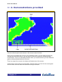
2.1 Introduction
The demonstration programs that are pre-installed on the RC100 Board are provided for
testing and demonstrating the RC100 Board. Note that the source code is not available for
these demonstrations except for the Breakout and Celoni racer programs, which are
provided as tutorials. See the RC100 Tutorial Manual for more information on the tutorials.
The demonstration programs are stored on the board in Flash RAM. If you overwrite the
demonstrations, you can upload them again by using the File Transfer Utility (Section 3.2).
To use the demos, set up the board:
1. Make sure that the Autoboot switch is on, and all the others are off. For more
information about switches, refer to the RC100 Hardware manual.
2. Connect a PS2 mouse, monitor, camera and power supply to the board. Set the
monitor to a 640 * 480 display.
3. Switch on the power.
You will see the Menu Screen displayed on your monitor. The Menu Screen allows you to
select the other demos.
Note that the peripheral devices should be connected before the RC100 Board is
turned on. Otherwise the devices may not function correctly.
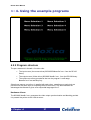
2.1.1 Menu screen for RC100 demonstrations
This application is used as a menu system for selecting all other demonstration programs.
You can select the other programs by moving the mouse over the appropriate text and
clicking the left mouse button.
>: Chapter :2
5
RC100 User Manual
>: 2. Demonstrations provided
Parallel processing
The menu screen demo shows how important parallel computing is when running at a low
clock frequency. The demo is mixing the rotating background with the moving lights, the text
and the logo. This is possible because the calculations for each procedure are done in
parallel.
The video stream is generated at a rate of one pixel per clock cycle, so no video buffer is
required.
2.1.2 Windows
This demo displays two windows. One contains a bouncing ball and the other contains a
demonstration of the classic computer science problem popularly known as the “Conway’s
Game of Life”.
•
You can use the mouse to move the windows around.
•
You can click the right mouse button in the window with the bouncing ball to
alternate between a transparent and opaque background.
>: Chapter :2
6
RC100 User Manual
>: 2. Demonstrations provided
•
To start the game of life, click the left mouse button anywhere in the “Life”
window. Each individual element survives according to the number of neighbours
it has. It dies if there are too many or too few.
•
Once the game has started, you can click the left mouse button to spawn life. If
you press the right mouse button, the screen is cleared. If you press both mouse
buttons together the screen will pause, enabling you to use the right button to
single step through the life process. To resume normal play, press both mouse
buttons together.
•
To return to the menu screen, click the cross in the top right corner.
Parallel processing
This is another demonstration of the power of parallelism. You'll notice as you move the
windows around that the animations inside do not glitch, no matter how fast you move the
>: Chapter :2
7
RC100 User Manual
>: 2. Demonstrations provided
mouse. This is because each window is being generated by a completely separate piece of
hardware on the FPGA. If this demonstration were implemented on a real-time operating
system, you would be able to notice decreased performance as the windows were moved
around.
Video management
The program "scans" the screen area and decides what colour the pixel at the current
position should be, depending on what the window processes are doing.
The video stream is generated at a rate of one pixel per clock cycle, so no video buffer is
required.
2.1.3 Venus de Milo
This program uses video from the camera and displays it in a rotating room with the Venus
de Milo as the centrepiece.
To stop or start the rotation at any time click the left mouse button.
To return to the menu screen right click the right mouse button while the Venus de Milo is
rotating.
If there is no input from the camera, a grey box rotates around the Venus de Milo.
>: Chapter :2
8
RC100 User Manual
>: 2. Demonstrations provided
This demo displays a complex graphical image, rotating within a room, while displaying and
processing live video.
The FPGA generates one pixel per clock cycle, giving a frame rate of 60fps.
To do this type of processing you would usually need a very high performance processor.
Techniques used to achieve this rely on Handel-C features, such as parallelism, pipelining,
and adjustable width variables. For information how to use these, refer to the RC100 Tutorial
manual or to the online help supplied with DK1.
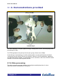
2.1.4 Video processing
The video processing program detects moving objects and displays them in colour.
Stationary objects are displayed in dark grey.
>: Chapter :2
9
RC100 User Manual
>: 2. Demonstrations provided
Input from the camera is combined with a screen showing moving balls. If the balls are “hit”
by a moving image (received from the camera) they bounce and change colour from green
to red.
To return to the menu screen, use the moving object in front of the camera (e.g. your hand)
to touch each of the stationary balls on the right side of the screen in order from top to
bottom.
Information
This program compares previous images from the camera with the current image. The
image-processing is performed in real time and would require a high performance processor
to perform the same task on a standard PC.
>: Chapter :2
10
RC100 User Manual
>: 2. Demonstrations provided
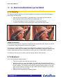
2.1.5 Squishy
The squishy program allows you to stretch regions of an image by selecting and dragging
them with a mouse pointer.
•
Left-click the mouse button to grab the parts of the image and keep the left
mouse button pressed down whilst you stretch them out.
•
To reset the image to normal, left-click the R in the top left corner.
•
To return to the menu screen left-click the cross in the top right corner.
Image manipulation
The FPGA on the board is configured to implement the mouse and video drivers, as well as
to perform the image-processing required for the game.
The image is morphed between the original image and the adjusted image using a sine
function and a vector map. The offsets of the image are calculated in real time, and the video
stream is generated at a rate of one pixel per clock cycle, so no video buffer is required.
The external memory is only used to store the image and the offset vectors.
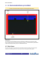
2.1.6 Breakout
This is the traditional breakout game.
•
To start the game press the left mouse button.
•
Move the mouse to control the paddle. You knock the ball against the bricks to
eliminate them and get points. If the ball hits the bottom line it is lost. Your current
score is shown in the top left corner and the previous highest score is in the top
right corner. Each time you play you get 3 balls. When the game is over the ball
stays in the centre of the screen.
•
Use the left mouse button to restart the game.
>: Chapter :2
11
RC100 User Manual
>: 2. Demonstrations provided
•
To return to the menu screen at any time, click the right mouse button.
Information
The FPGA on the RC100 Board has been configured to implement the mouse and video
driver in parallel with the processing required for the game. The video stream is generated at
a rate of one pixel per clock cycle, so no video buffer is used.
2.1.7 Boat Game
The aim of this game is to get the boat to the finish line without crashing. The boat travels
forward at a constant speed and it is your job to steer it through the water system.
>: Chapter :2
12
RC100 User Manual
>: 2. Demonstrations provided
Click the left and right mouse buttons on the mouse to steer the boat.
Once you’ve completed the course or have crashed the boat, you can restart the game by
clicking the left mouse button or exit and return to the menu screen by clicking the right
mouse button. There is a small delay between when you crash and when you can restart the
game so that accidental resets do not occur.
There is a map of the course in the bottom left hand corner of the screen.
At the bottom of the screen are several bars. The first shows your time for the current game
and the others show the best times achieved during the session.
>: Chapter :2
13
RC100 User Manual
>: 2. Demonstrations provided
Information
The FPGA on the board is configured to implement the mouse and video drivers in parallel
with the processing required for the game. The rotation angles and angular velocity of the
boat are all calculated in real time, which results in very smooth rotation compared to a
similar game played on a computer. The video stream is generated at a rate of one pixel per
clock cycle, so no video buffer is required. This demo does not use the SSRAM chips on the
board. The map image is loaded from Flash RAM.
2.1.8 Celoni racer
This is like a 3D version of the boat game.
•
Drive the vessel around the course. You don't need to worry about crashing, as
you rebound off the banks if you hit them.
•
Move the mouse to turn left and right and use the left mouse button to accelerate.
•
You can return to the menu screen by clicking the right mouse button.
>: Chapter :2
14
RC100 User Manual
>: 2. Demonstrations provided
Information
The game demonstrates a number of important techniques for producing high-performance
hardware using Handel-C. The FPGA on the board has been configured to implement the
mouse and video drivers in parallel with the processing required for the game.
The landscape in the game is represented using a height-map (or height-field). This is a twodimensional grid with each point on the grid having an associated height, similar to a topdown contour map. The map image is loaded from Flash RAM. The video stream is
generated at a rate of one pixel per clock cycle, which produces a frame rate of 60fps.
This application is described in more detail in the RC100 Tutorial Manual.
2.2 Reloading the demonstrations
The demos are stored on the board in Flash RAM. If you overwrite the demos, you can
transfer them onto the board again by using the File Transfer Utility (Section 3.2).
A script file (Load Demos Script.txt) is provided with all the commands necessary to
transfer the data. The default location for the file is RC100/Demos.
>: Chapter :2
15
RC100 User Manual
>: 2. Demonstrations provided
You can execute this script by pressing the Use Script button on the main File Transfer
Utility dialog (Section 3.3.3).
A map of the locations of the demonstrations in Flash RAM is given in Appendix B.
>: Chapter :2
16
RC100 User Manual
>: 3. Transferring files
>: 3 Transferring files
3.1 Introduction
The Celoxica File Transfer Utility allows you to transfer your files between your PC and the
RC100 board via a parallel port cable.
This allows you to test new Handel-C designs by:
•
transferring an FPGA configuration file directly to the FPGA on the RC100 Board
•
transferring completed Handel-C designs to the RC100 board’s Flash memory for
future execution.
You also need to use the File Transfer Utility to run the software examples and the tutorials
provided in the RC100 support software.
You can configure the File Transfer Utility and execute file transfers in three ways:
•
select commands using the GUI
•
type commands into the command prompt built into the main File Transfer Utility
dialog
>: Chapter :3
17
RC100 User Manual
>: 3. Transferring files
•
run a script file containing commands
The message log stores a list of recently executed commands.
3.1.1 DriverLINX device driver
The program uses the DriverLINX device driver that is provided on the RC100 Software
Support CD. The latest version can be downloaded without charge from the Scientific
Software Tools, Inc. website:
http://www.sstnet.com.
3.1.2 File Transfer Utility performance
It takes approximately 5 seconds per megabyte to transfer a configuration file to the FPGA.
Data is written to the Flash memory at approximately 60 seconds per megabyte. The
performance of the File Transfer Utility program may be reduced if you have a PC that is
significantly below the recommended system requirements.
3.2 Transferring files
You can use the File Transfer Utility to:
•
Transfer Xilinx® BIT files to the FPGA
•
Transfer files or raw data from your PC to a specified location in the Flash RAM
•
Transfer files or raw data from the Flash RAM to your PC
3.2.1 Configuring the File Transfer Utility
1. Connect the RC100 board to the parallel port on your PC with an IEEE 1284
compliant cable.
2. Switch on the board.
3. Start the File transfer program by selecting Start>Programs>RC100>File
Transfer Utility.
4. Ensure the correct parallel port is selected. The program automatically detects
ports at locations 378h (LPT1) and 278h (LPT2). If your port is at a non-standard
location, type:
SetPPTBase Address
at the command prompt, where Address is the location of the port. Specify the
address as either a decimal or a hexadecimal number.
>: Chapter :3
18
RC100 User Manual
>: 3. Transferring files
3.2.2 Transferring files to Flash RAM
1. Configure the File Transfer Utility as described above.
2. Select Flash from the Device drop-down list.
3. Specify the Flash location you want to transfer the file to by entering a decimal or
hexadecimal number in the Address Offset box.
By default, the program will write to location zero in the Flash memory (the ‘boot’
sector).
4. Click Write. This opens the Open file dialog.
5. Browse and select the file you want to transfer to Flash RAM. The transfer will
begin immediately, and the activity indicator will light up. You will see information
about the progress of the data transfer in the message log.
Do not disconnect the board from the PC whilst the activity indicator is lit.
3.2.3 Transferring files to the FPGA
1. Configure the File Transfer Utility as described above.
2. Select FPGA from the Device drop-down list
3. Click Write. This causes the Open file dialog to appear.
4. Browse and select the file you want to transfer to the FPGA. The transfer will
begin immediately. The activity indicator lights whilst data is being transferred.
You will also see information about the progress of the data transfer in the
message log window.
3.2.4 Transferring files from the board to your PC
1. Configure the File Transfer Utility as described above.
2. Select Flash from the Device drop-down list
3. Specify the location of the file you want to read in the Address offset box.
4. Enter the exact number of bytes of the file you want to read in the Size box.
5. Click Read. This opens the Save As dialog box.
6. Browse to select the directory where you want to save the file.
7. Enter the filename you want to use. The transfer will begin immediately. The
activity indicator lights whilst data is being transferred. You will also see
information about the progress of the data transfer in the message log window.
>: Chapter :3
19
RC100 User Manual
>: 3. Transferring files
3.2.5 Stopping a transfer
You can stop a file transfer at any time by clicking the Stop button.
3.3 Using commands and script files
You can type commands at the command prompt in the main File Transfer Utility dialog, or
execute them from a script file. They will be interpreted by the command parser, and acted
upon accordingly.
If you mistype a command or if the parameters are invalid, it will simply be ignored by the
command parser. The command parser is not case-sensitive.
You can repeat recently executed commands by selecting them from the drop-down list box
next to the Repeat button, then clicking Repeat.
You can recall commands typed at the command prompt by pressing the up or down arrow
keys.
The message log displays previously executed commands and any messages generated in
response. You can copy these into a text file or onto a clipboard (Section 3.4.1).
>: Chapter :3
20
RC100 User Manual
>: 3. Transferring files
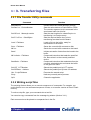
3.3.1 File Transfer Utility commands
Command
Function
AutoDetect
Initiates automatic board detection process.
SetDevice DeviceNumber
Sets the active device to Flash RAM or FPGA.
The numeric argument to this command is the
zero-based index into this list.
SetOffset MemoryLocation
Sets the start location for a data file prior to
transferring it to Flash memory.
SetFileSize SizeInBytes
Sets the required buffer size, prior to
transferring raw data from the board.
Load FileName
Save FileName
Loads a file into the buffer, ready for
transmission to the board.
Saves the current buffer contents to disk.
Write
Sends the current buffer contents to the board.
Read
Initiates a transfer of data from the board to the
buffer.
WriteAuto FileName
Compound instruction that loads the specified
file, then writes it to the currently selected
device.
ReadAuto FileName
SetLPT LPTNumber
Compound instruction that reads data from the
currently selected device and saves the buffer
to the given file name.
Selects the parallel port by LPT number.
SetPPTBase Address
Selects the parallel port by base I/O address.
Use ScriptFileName
Executes the named script.
Stop
Halts any currently active process.
Quit
Closes the application
3.3.2 Writing script files
The scripting feature allows you to execute a sequence of commands. For example, you
could use this to run an automated sequence of tests, or to transfer a series of files to Flash
memory.
To write a script file, type your commands into a text file.
You can also copy commands from the message log window (Section 3.4.1).
Each command must be placed on a separate line in the file.
>: Chapter :3
21
RC100 User Manual
>: 3. Transferring files
Unrecognized or misspelled commands are ignored. Execution continues with the next line
in the script file.
Comments in script files
All text that isn't recognized as a command is assumed to be a comment.
For ease of reading, it is recommended that you surround comments in brackets. For
example:
[This is a comment]
To comment a warning, prefix the comment with an exclamation mark:
![Stranger danger]
3.3.3 Executing script files
1. Configure the File Transfer Utility (Section 3.2.1).
2. Click the Use script button.
3. Browse and select the script file you want to use, or type
Use ScriptFileName
in the command prompt.
The progress bar will indicate the progress of the individual activity currently being executed
(not the progress of the script file itself).
You can terminate a script at any time by clicking the Stop button.
3.4 Information in the message log
The message log appears in the right hand pane of the main File Transfer Utility dialog.
Each new action causes some additional text to appear at the bottom of this window.
You can scroll through recent entries using Page Up and Page Down on your keyboard or by
using the arrows or the hand on the scroll bar. The outer set of arrows takes you to the start
or the end of the list.
The text in the message log is coloured according to its origin:
Green
Black
Purple
Blue
-
>: Chapter :3
Commands automatically generated by pressing buttons
Commands typed manually at the command prompt
Messages generated by the parallel port handler
Messages generated by the board handler
22
RC100 User Manual
>: 3. Transferring files
Grey
Red
-
Intermediate messages or commands
Error messages
3.4.1 Copying commands from the message log
You can copy commands from the message box onto a clipboard or into a text file. This
allows you to create or add to script files.
Copying commands to a text file
1. Press the Save icon at the bottom right of the dialog. This will open the Save As
dialog.
2. Select a name and location for the text file.
You can then execute the commands by using the text file as a script file (Section 3.3.3).
Copying commands to a clipboard
To save the contents of the message log window into a clipboard, press the Copy icon at the
bottom right of the dialog.
>: Chapter :3
23
RC100 User Manual
>: 4. Using the example programs
>: 4 Using the example programs
4.1 Introduction
This chapter describes the example programs provided in the RC100 support software and
describes how you can modify them. These programs demonstrate some of the features of
Handel-C such as pipelining, channels and prialts.
4.1.1 Example programs
The RC100 support software contains the source code for three example programs:
•
Menu Screen program – a simple program that demonstrates how to reconfigure
the FPGA from files stored in Flash RAM.
•
Text Editor program – a simple program that demonstrates how to interface with
a keyboard and mouse
•
Sobel Edge Detect program – a more advanced program that demonstrates how
to use the FPGA for real-time image-processing. The program shows how to use
two clocks set at different speeds.
4.1.2 Setting up DK1
In order to build the example programs you must set your environment variables to access
the RC100 library and include files.
1. Start DK1 (For the default installation, select Start>Programs>DK1 Design
Suite>DK1.)
2. Select the Options command from the Tools menu.
3. In the dialog that appears, select the Directories tab.
4. In the Show directories for: drop-down list, choose Include files. Click Add. In
the dialog that appears, you may browse for the directory containing the RC100
include files or type the full pathname in the Directories name pane. The default
path is RC100\Include
For example, C:\Program Files\Celoxica\RC100\Include
5. Choose Library files from the Show directories for: drop-down list. Add the
directories containing the RC100 libraries. By default, this path is RC100\Lib
For example, C:\Program Files\Celoxica\RC100\Lib
>: Chapter :4
24
RC100 User Manual
>: 4. Using the example programs
4.1.3 Using the examples
To use the examples you will need to compile the programs and produce Xilinx BIT files:
1. Set up DK1 and set your environment variables to access the RC100 library and
include files (Section 4.1.2).
2. Open the workspace for the example. The default location for the example
programs is Program Files/Celoxica/RC100/Examples
3. Set the active configuration to EDIF (Build>Set Active Configuration)
4. Check that the correct device is targeted on the Chip tab in the Project Settings
dialog. This should be Virtex series Xilinx FPGA.
5. Build the project. This will create a folder called EDIF within your project
containing an EDIF netlist and a netlist constraints file (.ncf).
6. Use your Xilinx tools to place and route the netlist. If you are going to access the
program from Flash memory on the board, you need to compile your application
with Done Cycles equal to 6 and the start-up clock equal to CCLK. This is
described in Section 4.1.4.
7. Use the File Transfer Utility to load the BIT file, and any associated data onto the
board. This is described in more detail for each example program below.
4.1.4 Setting Done Cycles and the Start-up clock in Xilinx
Design Manager
If you want to access programs from Flash memory (e.g. via the Menu Screen example
program), you need to compile the programs with Done Cycles equal to 6 and the start-up
clock equal to CCLK. You need to change this in the Options dialog in Xilinx Design
Manager:
1. Open the Options dialog, and press the Edit options button for Configuration
(the second Edit Options button). This will open a new dialog: Spartan 2
Configuration Options: Default.
2. Select the Startup tab, and change the value for Done to C6 and the start-up
clock to CCLK.
4.2 Menu Screen program
The Menu Screen program shows you how to:
•
reconfigure the FPGA from files stored in Flash RAM
•
use the RC100 board to interface with a monitor and a PS2 mouse
•
edit and store a background image file
•
use the Handel-C par statement for parallel processing
>: Chapter :4
25
RC100 User Manual
>: 4. Using the example programs
The menu screen has six designated areas that can be used to access programs in Flash
memory on the board. If you place the mouse pointer over a designated area, its colour
changes from white to yellow.
You can modify the example code to link programs stored in Flash RAM to these predefined
areas, or to change the number and size of predefined areas.
Once you have linked programs to the predefined areas you can reconfigure the FPGA by
clicking the left mouse button over one of these areas.
4.2.1 Loading the Menu Screen program
1. Open the workspace for the example in DK1 (menu.hw).
2. Compile the program and produce the Xilinx BIT file (see Section 4.1.2)
3. Connect a monitor and a mouse to the board. Set the monitor to a 640 * 480
display.
4. Choose the sector on the Flash RAM you want to load the BIT file to and then
configure the other switches.
For example, turn on switch 1 if you are loading to sector 1, or turn on switches 2
and 3 if you are loading to sector 6.
(This is not necessary if you want to load the program to sector 0).
5. Use the File Transfer Utility (Section 3.2) to transfer the relevant files:
First, load the background image for the program, menu.raw, to Flash location
0x380000 Note that this will overwrite whatever was previously stored in the
Flash.
Then transfer the BIT file to the chosen sector on the Flash RAM.
>: Chapter :4
26
RC100 User Manual
>: 4. Using the example programs
4.2.2 Program structure
The par statement in the main function calls:
•
The input macro (the mouse driver) RC100PS2MouseDriver from the RC100
library.
•
The output macro (Video driver), RC100VideoDriver, from the RC100 library.
•
The continuous macro procedures that run the program: LoadImage,
MenuSelection and Display.
Since these macros, are all run in parallel with each other, operations on each pixel are
performed at the same time as outputting them to the screen. This demonstrates the
advantages that Handel-C gives over sequential languages like C.
Hardware drivers
The RC100VideoDriver generates the video output synchronisation and blanking periods.
It is passed the pointer to the VGA structure.
>: Chapter :4
27
RC100 User Manual
>: 4. Using the example programs
Each pixel takes one clock cycle. Then a blanking period occurs before the next
frame is drawn to the screen.
The RC100PS2MouseDriver produces the feedback from the mouse. It is passed the
pointer to the mouse structure and which PS2 port to use.
The precompiled library functions in the RC100.lib are described in more detail in the
RC100 Function Library Manual.
LoadImage macro
The LoadImage macro loads an image file from a predefined area in Flash RAM and stores
it in the SSRAM. The Flash RAM location is defined at the beginning of the source code and
can be easily modified.
The macro reads each 8-bit colour element from a specified location in Flash RAM, and then
stores the resulting 24-bit colour pixel.
The LoadImage macro is run before the Display and MouseSelection macros so that
the memory is initialized before the output is displayed. This prevents unwanted data being
displayed.
MenuSelection macro
The MenuSelection macro determines whether the mouse pointer is within one of the
predefined areas. If this is true it sets an offset flag for the Display macro. It also checks
whether the left mouse button is pressed. If it is, the FPGA reconfigures itself with a file from
Flash RAM depending on which area was selected.
Display macro
The Display macro is pipelined into two parts that run in parallel. One part reads which
colour should be displayed next from the RAM. The other part provides continuous output of
the video signal, resulting in the colour being displayed on the screen. It also performs two
calculations:
•
It determines the location of the mouse pointer on the screen and displays the
mouse pointer instead of the output signal in this area.
•
If the mouse pointer is within one of the pre-defined areas that describe the files
available for download, it offsets the colour before it is displayed. This changes
the colour of the mouse pointer from white to yellow.
>: Chapter :4
28
RC100 User Manual
>: 4. Using the example programs
4.2.3 Modifying the program
If you want to add, remove or change items displayed in the menu program you need to:
1. Change the background image.
2. Save the image in raw file format.
3. Set the coordinates for any new menu items, or change the coordinates to fit the
length of the text inserted for a menu item.
4. Specify the start location of the Flash for each program accessed from the menu
at the beginning of the menu.c file.
5. Recompile the program and transfer the new files to the board, as described in
Section 4.2.
Changing the background image
You need to change the background image of the menu screen example to specify the
names of the programs you wish to access from the menu.
The background image, menu.raw, is stored in 24-bit Raw File Format. It does not contain
header information and is interleaved in the following format (RGB RGB…). The image is
also provided in a Paint Shop Pro file format (menu.psp), which may be easier to modify.
To change the background image:
1. Make changes to the image file using a graphics editor. Alternatively you can
substitute a new image.
2. Save the new image in Raw File Format. If you do not have any software that can
save as Raw File Format you can save as a bitmap and use the bmp2raw utility
described in Appendix A.
3. Transfer the new file to Flash RAM using the File Transfer Utility.
Graphic files loaded from Flash RAM use a 24-bit Raw File Format without header
information. Other formats will not work with this program.
Saving the image in raw file format
If you do not have any software that can save as Raw File Format you can save as a bitmap
and use the bmp2raw utility provided in the support software (see Appendix A).
Setting coordinates for a new item on the menu
The SetArea macro is used to set the coordinates of menu items in the ROM. These
coordinates describe an imaginary box around each menu item. For example, the
>: Chapter :4
29
RC100 User Manual
>: 4. Using the example programs
coordinates for Menu Selection 1 are the top left corner (40, 35) and the bottom right corner
(235, 60). This translates to the following line in the code:
SetArea(40, 35, 235, 60)
The order in which the items are stored in the RAM determines the configuration vector sent
to the Flash RAM.
To set the coordinates for a menu item:
•
Map an arbitrary box around it by entering the coordinates into the SetArea
macro.
4.3 Text Editor program
The Text Editor program allows you to enter text and simple commands with a keyboard,
and to change the colour of text. It displays the results on a VGA screen. Both the mouse
and keyboard can control the cursor.
Once you have started the program you can:
•
move the cursor by left-clicking anywhere in the white area of the screen
•
enter text at the cursor
•
change the colour of subsequent text by clicking one of the colours at the bottom
of the screen
•
use simple keyboard commands
The keyboard commands recognized by the program are:
•
Text-editing: Return; Backspace; Delete; Ctrl-Alt-Del. Ctrl-Alt-Del clears the
screen.
•
Cursor control: left, right, up and down arrows; Home; End; Ctrl-Home; Ctrl-End.
All other keyboard keys are ignored.
The Text Editor program shows you how you how to:
•
use the RC100 board to interface with a monitor, PS2 mouse and keyboard
•
use the Flash RAM on the board
•
use the Handel-C par statement for parallel processing
4.3.1 Loading the Text Editor program
1. Open the workspace for the example in DK1 (TextEditor.hw).
>: Chapter :4
30
RC100 User Manual
>: 4. Using the example programs
2. Compile the program and produce the Xilinx BIT file (see Section 4.1.2).
3. Connect a monitor, a mouse and a keyboard to the board. Set the monitor to a
640 * 480 display.
4. Use the File Transfer Utility (Section 3.2) to transfer the relevant files:
First load the font file font.raw to Flash location 0x300000. Note that this will
overwrite whatever was previously stored in the Flash.
Then transfer the BIT file to the FPGA.
4.3.2 Program structure
The par statement in the main function calls:
•
The input macros (the mouse and keyboard drivers), RC100PS2MouseDriver
and RC100PS2KeyboardDriver, from the RC100 library.
•
The output macro (Video driver), RC100VideoDriver, from the RC100 library.
•
The continuous macro procedures that run the program: Initialise,
KeyboardInterface, Write, MouseClick and Display.
>: Chapter :4
31
RC100 User Manual
>: 4. Using the example programs
Since these macros, are all run in parallel with each other, operations on each pixel are
performed at the same time as outputting them to the monitor. This demonstrates the
advantages that Handel-C gives over sequential languages like C.
Hardware drivers
The RC100VideoDriver generates the video output synchronisation and blanking periods.
It is passed the pointer to the VGA structure.
Each pixel takes one clock cycle. Then a blanking period occurs before the next
frame is drawn to the screen.
The RC100PS2MouseDriver produces feedback from the mouse. It is passed the pointer
to the mouse structure and which PS2 port to use.
The RC100PS2KeyboardDriver produces feedback from the keyboard. It is passed the
pointer to the keyboard structure, which PS2 port to use, and a description output format to
use.
The precompiled library functions in the RC100.lib are described in more detail in the
RC100 Function Library Manual.
Initialise macro
The Initialise macro initializes the SSRAM bank 0 to spaces (0x20). This clears the
screen of unwanted characters. The second part of this macro loads the font file from Flash
RAM, and stores it at the beginning of the SSRAM.
The fonts are stored as bitmaps and are read from memory when they are displayed. Their
location in Flash RAM is defined at the beginning of the source code and can be easily
modified.
The Initialise macro is run before the other macros so that the memory can be
successfully initialized before the output is displayed. This prevents unwanted data being
displayed.
KeyboardInterface macro
The KeyboardInterface macro determines what to do with the data returned from the
keyboard. The program waits for input from the keyboard passed via a channel. After this
has been received it checks whether the character is a control character or an ASCII
character.
If it is a control character the program runs a switch statement and performs the appropriate
action. For example, if ‘Home’ is pressed the cursor is returned to the left side of the screen.
>: Chapter :4
32
RC100 User Manual
>: 4. Using the example programs
If the input is a valid ASCII character it will be stored in the appropriate location in RAM and
the cursor will be moved to the next position.
Write macro
The Write macro stores the ASCII characters. This is a protected write, meaning that if the
memory is in use, it will wait until it is free before writing. This prevents multiple accesses on
the same clock cycle that would otherwise corrupt the data.
MouseClick macro
The MouseClick macro determines what to do when mouse buttons are pressed. There
are three parts to this macro:
•
If the right mouse button is pressed the FPGA reconfigures itself with whatever
program is stored in Flash RAM at location zero. This is usually a menu program
resulting in the menu screen being displayed on the VGA.
•
If the left mouse button is clicked on the colour palette the macro changes the
cursor colour and the text to the selected colour, starting with the next character
to be typed.
•
If the left mouse button is pressed anywhere in the text area, the cursor will be
repositioned to that location.
Display macro
The Display macro is pipelined into two parts that run in parallel. One part loads the ASCII
character specified by input from the keyboard from RAM and works out which part of the
bitmap to display in each clock cycle. As each character is 8 bits wide the process is broken
down to two sequential processes running in parallel and lasting 8 clock cycles. The other
part of the macro provides the output signal. It calculates whether the mouse pointer or the
result from the first part of the macro should be displayed.
4.3.3 Modifying the program
Adding more keyboard functions
The Text Editor program recognizes 12 control characters. These are listed in the switch
statement in the KeyboardInterface macro procedure in editor.c
ASCIIChars.h lists additional control characters which have been assigned. You can add
these functions to theText Editor program by adding them as new cases in the switch
statement. For example, to add in the “Insert” control:
>: Chapter :4
33
RC100 User Manual
>: 4. Using the example programs
case ASCII_CTRL_INSERT:
par
{
// Enter your code here
}
break;
Only ASCII codes 0-127 are supported for this program. This means you cannot use
the function keys, number pad keys, or Print Screen, Scroll or Pause/Break.
Adding text selection with the mouse
Text selection (highlighting text with the mouse) could be used as part of a text editing
function. For example, you might want to select text before cutting and pasting it elsewhere.
To add this feature you need to:
1. Edit the MouseClick macro, so that when you click and drag the mouse, a
region is selected. You need to specify starting and end coordinates for the
action.
•
Store the start coordinates from the point where the user first clicks the left
mouse button.
• Store the end coordinates from the point where the user releases the left
mouse button.
2. Edit the Display macro to add a function that inverts the colour output within the
selected area.
4.4 Sobel Edge Detect program
The Sobel Edge Detect program demonstrates the use of Handel-C in a real time image
processing application.
Video data is read from a camera and a Sobel Edge Detection algorithm is applied to the
data. The results are output to a VGA screen.
The program compares groups of pixels with their immediate neighbours. If there is no
difference, nothing will be shown on screen. If there is some difference (e.g. different shades
of grey), a faint “edge” will be seen. Distinct changes in colour will show up as a clear “edge”
on the screen.
The Sobel Edge Detect example program shows you how to:
>: Chapter :4
34
RC100 User Manual
>: 4. Using the example programs
•
Process video input from a camera, using the Philips SAA7111A Enhanced Video
Input Processor (EVIP) on the RC100 board.
•
Use two separate clocks running at different clock speeds.
•
Communicate between clock domains using channels.
•
Use multi-port block RAMs to buffer data.
•
Use a pipeline to optimize code.
The program has a modular design, allowing you to add, change or remove functions. For
example, you could remove the display process and add in some further image processing
functions.
4.4.1 Loading the Sobel Edge Detect program
1. Open the workspace for the example in DK1 (EdgeDetect.hw).
2. Compile the program and produce the Xilinx BIT file (see Section 4.1.2)
3. Connect a monitor and a video camera to the board. Set the monitor to a 640 *
480 display.
4. Transfer EdgeDetect.bit to the chosen sector on the FPGA using the File
Transfer Utility (Section 3.2).
>: Chapter :4
35
RC100 User Manual
>: 4. Using the example programs
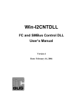
4.4.2 Program structure
The operation of the program is shown below. Processes running within the FPGA are
denoted using circles. Lines with arrowheads represent channels between two processes;
the arrowheads indicate the direction in which data is sent down the channel. A line with no
arrowhead indicates a simple connection to a device.
The design is split into two clock domains, shown by a dotted line on the diagram.
>: Chapter :4
36
RC100 User Manual
>: 4. Using the example programs
Video
Chip
DAC
Clock
Domain B
Read
Interlaced
Data From
Camera
Display Data
on Screen
Clock
Domain A
Spartan II 200
Deinterlace
Data to RAM
Read Data
from RAM
SRAM 0
Buffer Data
SRAM 1
HIGH-LEVEL DESIGN OF THE SOBEL EDGE DETECT PROGRAM
>: Chapter :4
Edge
Detection
Algorithm
37
RC100 User Manual
>: 4. Using the example programs
Using multiple clock domains
The interface to the video decoder chip is clocked at the same speed as the clock on the
chip (27MHz). The rest of the FPGA is clocked by the main oscillator running at 80MHz. This
is divided by three or four, depending on which Handel-C program is running. More
information on the use of clocks with Handel-C is given in the Handel-C Language
Reference Manual in the DK1 online help.
4.4.3 Reading and storing data input
Reading input from the camera
The Edge Detect program uses the RC100VideoDecoder driver from the RC100 library to
read data input from the camera.
Communication between clock domains
A FIFO buffer, implemented in block RAM, passes data between the two clock domains.
Synchronisation is achieved using Handel-C channels, which abstract away from the
programmer the complexities of communication between different clock domains.
Writing data into SSRAM
The input data from the camera is interlaced. This needs to be de-interlaced before the data
is stored in the SSRAM. The input data from the process reading from the camera clock
domain contains positional information so that the lines can be written to the correct location.
Once a frame is complete, the reading process reads the de-interlaced data from this RAM
bank whilst the de-interlacing process switches to the other SSRAM bank to write the next
frame. The de-interlacing process sets a 1-bit variable to control which RAM bank is being
written to.
4.4.4 Processing and displaying stored data
Reading data from SSRAM
This process uses the RC100ReadSSRAM0 driver from the RC100 library to read an image
out of the SSRAM. The image is equal in size to the visible area of the screen, set by
constants from the RC100 video library.
The reading process switches between the two RAM banks, to alternate with the writing
process described above.
>: Chapter :4
38
RC100 User Manual
>: 4. Using the example programs
Buffer management
Spatial image filters, such as Sobel Edge detection, operate on a square area of pixels from
an image. The Sobel Edge Detect program operates on a 3 by 3 pixel area. In order to
access a 3 by 3 area of an image in a single clock cycle, data from the RAM needs to be
stored in buffers.
The process for updating the buffers is implemented using replicated par statements. This
means you can easily extend the code for different size matrices.
The buffer management process takes an input of one pixel from a channel and outputs a 3by-3 array down a channel to the image-processing algorithm every clock cycle.
Two FIFO buffers are used. Each stores a line of the image, minus the three pixels that are
stored in the array. Every clock cycle, a pixel received from the RAM reading process is put
into the bottom right corner of the array. The contents of the array are shifted to the left, with
the leftmost member being added to the tail of the FIFO. The top left pixel is now finished
with and can be written over without storing it anywhere else.
The FIFOs are implemented using circular buffers constructed from multi-port block RAM
with an index keeping track of the front item in the buffer.
The availability of multi-port block RAM in the Spartan II FPGA means that you can read and
write to the RAM in the same clock cycle. This allows a throughput of one pixel per clock
cycle. The same effect can be achieved using double-width RAMs implemented in lookup
tables on the FPGA. However, the use of block RAMs is more efficient and has less
associated logic for reading and writing.
>: Chapter :4
39
RC100 User Manual
>: 4. Using the example programs
Edge detection algorithm
In this example code, each colour is processed individually and the results make up a single
pixel. 3 by 3 arrays for each colour arrive down the input channel and 16 bit pixels are
output.
A wrapper process (ProcessVideo) takes pointers to an input channel, an output channel
and the image processing function as arguments. A constant integer value parameter is also
passed to the wrapper function. This constant is the number of clock cycles that the image
processing function takes to produce an output at the end of the pipeline from an input.
The image processing function (ProcessWindowSobel) takes a pointer to the set of three
3 by 3 arrays representing the three colours of the 3 by 3 area of the image as one
parameter, and a pointer to a 16 bit pixel as the second, into which the output will be written.
This means you can substitute a new image processing function without needing to make
any changes to the rest of the code.
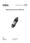
Sobel edge detection is performed using two 3 by 3 matrices, one for horizontal edges and
one for vertical edges. The two 3 by 3 matrices are shown below. The results of the
application of these two matrices to the 3 by 3 area of the image are then added together to
produce the final output.
Sobel operators (x and y direction)
The algorithm used in this program has been pipelined to produce one pixel every clock
cycle. The output for a given input appears at the other end of the pipe several clock cycles
later.
The algorithm has been implemented using a Handel-C macro procedure (Sobel). Macro
procedures are an alternative to functions in Handel-C and implement direct code
replication. They allow programmers to imply word width and sign and to use different widths
with each call to the macro. The Sobel macro procedure performs the same edge detection
algorithm on the red, green and blue components, even though the green component is a 6bit number and red and blue are 5-bit.
>: Chapter :4
40
RC100 User Manual
>: 4. Using the example programs
Displaying data on the screen
The RC100VideoDriver macro is used to generate scan data. When the current scan
position is within the visible area, the display process reads a pixel from its input channel.
4.4.5 Pipelining the data processing
The Sobel Edge Detect program uses a complex pipeline to accelerate the processing of
data.
Each of the processes below uses the scan position of the screen to ensure that they carry
out actions at the correct time:
•
Reading process: reads an image the size of the visible area of the screen from
the SSRAM bank not being used by the writing process.
•
Buffer process: copies information from the reading process into the buffers and
shifts data through the buffer at the right time so that valid (visible) data is input at
one end and output at the other
•
Image processing process: takes data at the correct time from the buffers and
passes the output to the display process
•
Display process: reads output from the image processing process and displays it
when it is required on the screen.
Possible solution
You could make process keep track of its own scan position. Each process would need to
calculate when the information that it reads and writes is visible and stall when it is not.
Two disadvantages of this are:
•
The work required in calculating the pipeline delays
•
The overhead of each process keeping track of its own scan position.
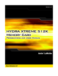
Efficient solution
An alternative approach is taken in the Edge Detect program. Each process produces the
data that the process downstream needs and blocks when the downstream process is not
ready to accept data.
>: Chapter :4
41
RC100 User Manual
>: 4. Using the example programs
Process P1
Block until process P2 is
ready
Process P2
Block until process P(n+1)
is ready
Process
P(n+1)
Process P(N1)
Block until process PN is
ready
Process PN
PIPELINING PROCESS
>: Chapter :4
42
Direction of Data Flow
Process Pn
RC100 User Manual
>: 4. Using the example programs
In the Edge Detect program, the display process is furthest downstream and so this stalls
the pipeline when it is not ready to take data. The display process only needs to take data
when the current scan position is in a visible area of the screen.
Achieving synchronisation
Synchronisation is achieved using a combination of signals and channels. The
ProcessVideo function, shown below, copies data over a number of clock cycles to the
output.
/*
inputs: WindowInChan - pointer to a 16 bit channel for incoming
data
outputs: OutChan - pointer to a 16 bit channel for outgoing data
process: pipeline to add latency to the propagation of data
*/
void ProcessVideo(chan WINDOW_PIXEL_16 *WindowInChan, chan unsigned 16
*OutChan, const unsigned ProcessDelay, void
(*ProcessWindow)(WINDOW_PIXEL_16 *Window, unsigned 16 *Pixel))
{
//window read in from input channel
WINDOW_PIXEL_16 Window;
//pixel to output
unsigned 16 Pixel;
/*
signal indicating whether or not data has been sent on a clock
cycle
*/
static signal unsigned 1 NoDataSent = 0;
//counter to delay the output of data while the pipe is primed
unsigned DelayCounter;
//read in the first window (blocks until data is available)
*WindowInChan ? Window;
>: Chapter :4
43
RC100 User Manual
>: 4. Using the example programs
par
{
while(1)
{
//if data has been sent
if (!NoDataSent)
{
par
{
//read in a new window
*WindowInChan ? Window;
//process the window
ProcessWindow(&Window, &Pixel);
}
}
else
delay;
}
{
//delay until the pipeline is primed
do
{
DelayCounter++;
}
while(DelayCounter!=(ProcessDelay+1)-1);
/*
send the data to the next process in the pipeline
if the send blocks, pause the pipeline update by
setting NoDataSent to 1
*/
while(1)
{
prialt
{
case *OutChan ! Pixel: break;
>: Chapter :4
44
RC100 User Manual
>: 4. Using the example programs
default: NoDataSent = 1; break;
}
}
}
}
}
The ProcessVideo function reads its input from the channel referenced by the pointer
WindowInChan and writes to the channel referenced by the pointer OutChan. If the
receiving channel is not ready to take the current data, the process stalls until it is.
A prialt statement is used ensure that the pipeline is not updated if a process has stalled.
In the prialt statement, the first case tries to send the output to the next process. If the
process is not ready to take the data, the default case of the prialt statement is executed,
setting a signal high. This signal is used to check whether or not to update the pipeline in the
same clock cycle. This code is highlighted in grey.
Hardware efficiency of prialts and signals
The prialt code block may look large, but it is extremely efficient.
Channels have what can be thought of as two wires, one from each side of the
communication, to indicate readiness. The prialt with a single case and default on the
sending side is implemented with a single-bit comparator, (as for a normal channel
communication), with the branch for an unsuccessful transmission setting the signal high.
The signal is implemented as a single wire with a single bit comparison in hardware.
4.4.6 Modifying the program
The Edge Detect program is modular, which means you can substitute, add or remove
processes. Some examples are given below.
Using a different image processing algorithm
You can substitute the call to the Sobel edge detection macro with a call to a different spatial
image processing macro.
It is important that you calculate the latency in clock cycles of the image processing process
correctly; otherwise erroneous data will appear in the output.
>: Chapter :4
45
RC100 User Manual
>: 4. Using the example programs
Adding stages to the pipeline
You can add extra pipeline stages by inserting a new function between two others in the
pipeline. For example you could add an image processing function (with its own buffers) that
smoothed the picture before the edge detection algorithm was performed.
The new function needs to copy the method of communication used in the other functions. A
template function is provided. This reads from a channel and copies the data into the output
channel.
It is important that the pipeline delay is calculated correctly; otherwise errors from later or
earlier data will filter downstream.
Pipelining multiple image processing functions
You can pipeline a number of image processing functions:
1. Take the output of one image processing function.
2. Copy it into a buffer for the next image processing function.
3. Process the output of the buffer.
Each set of buffers requires the use of multiport RAM, so there is a limited number of
functions that can be pipelined. An alternative is to use buffering that uses 32-bit wide RAMs
constructed from lookup tables on the FPGA, which can then be read and written in alternate
clock cycles.
Interpreting the data output from the edge detection
The Sobel Edge Detection program displays the results of the image processing on the
screen, but many applications need to interpret this data in order to make an analysis of the
image. The way in which the RAM is used in this application makes it difficult to do a
significant amount of interpretation, as the processed data is not stored in RAM.
Greyscale vs. full colour
The example code is written for full colour image processing, but you can adjust it to do grey
scale image processing. Greyscale image processing will reduce the amount of data storage
and logic produced.
In order to create the most efficient program possible, the grey scaling should be done at the
earliest moment – as soon as a pixel is read from the camera. This will reduce the amount of
RAM used to store a pixel, the size of registers for the pipeline stages and thus the logic
needed to manipulate the data through the pipeline. It should also be possible to pipeline
more image processing operations, as the buffers for storing the data will be smaller.
>: Chapter :4
46
RC100 User Manual
>: 5. Appendices
>: 5 Appendices
Appendix A. Bitmap / raw file format
utilities
5.1.1 Introduction
The Text Editor program only accepts images that are in raw file format. However, images in
BMP format may be easier to edit. The RC100 support software contains two utilities that
allow you to convert between these formats.
bmp2raw
converts BMP images to raw file format
raw2bmp
generates BMP image files from files in raw format. These may be easier
to modify with graphics editors.
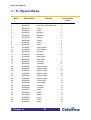
5.1.2 How to use the raw file / bitmap utilities
bmp2raw utility
The general usage of the bmp2raw utility is:
bmp2raw [-b] BMPFile RAWFile RGBFile
BMPFile
source image file
RAWFile
destination raw data file
RGBFile
file describing the format of the pixels in the raw data file
The format of the raw data file can be controlled with the RGBFile specified on the command
line. This tells the utility where to place each colour bit in the words in the raw data file.
Internally, the pixels in the BMP file are expanded to 8 bits for each of red, green and blue.
The RGB description file has the general format:
Red
Location for bit 7 of red
Location for bit 6 of red
Location for bit 5 of red
Location for bit 4 of red
Location for bit 3 of red
>: Chapter :5
47
RC100 User Manual
>: 5. Appendices
Location for bit 2 of red
Location for bit 1 of red
Location for bit 0 of red
Green
Location for bit 7 of green
Location for bit 6 of green
Location for bit 5 of green
Location for bit 4 of green
Location for bit 3 of green
Location for bit 2 of green
Location for bit 1 of green
Location for bit 0 of green
Blue
Location for bit 7 of blue
Location for bit 6 of blue
Location for bit 5 of blue
Location for bit 4 of blue
Location for bit 3 of blue
Location for bit 2 of blue
Location for bit 1 of blue
Location for bit 0 of blue
The file works by starting counting at bit 7 of the colour specified by the identifier word and
works down through the bits of that colour placing each bit in the specified location in the
destination word. The destination word will automatically be created wide enough to contain
the most significant bit specified (up to 32 bits wide in total).
You need not specify 8 locations for each colour. The least significant bits of each colour will
be dropped if fewer than 8 locations are specified. In the example below, the least significant
6 bits of red and blue and the least significant bits of green are dropped.
To generate 8-bit pixels in the raw file with the following bit pattern:
>: Chapter :5
48
RC100 User Manual
>: 5. Appendices
Raw file bit number
Colour bit
7 (Most significant)
Red 7
6
Green 7
5
4
Blue 7
Blue 6
3
Green 6
2
Red 6
1
0 (Least significant)
Green 5
Green 4
use the following RGBFile:
Red
7
2
Green
6
3
1
0
Blue
5
4
Each pixel number and identifier (Red, Green or Blue) must appear on a separate line.
You may also specify multiple identifiers of the same colour. The bit counter will continue to
count down from the value reached for that colour each time you specify the colour again.
For example, the above file could also be written like this:
Red
7
Green
6
Blue
5
Red
2
Green
3
1
>: Chapter :5
49
RC100 User Manual
>: 5. Appendices
Blue
4
Green
0
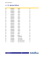
raw2bmp utility
The raw2bmp utility is the reverse of the bmp2raw utility. It converts binary files to BMP
image files.
The general usage of the raw2bmp utility is as follows:
raw2bmp [-b] Width RAWFile BMPFile RGBFile
Width
the width of the image. The height will be calculated from this parameter
and the source file length.
RAWFile
source file containing raw data.
BMPFile
destination image file.
RGBFile
file describing the format of the pixels in the raw data file.
The format of the RGBFile describing where each bit is located in the raw data word is
similar to the file used by the bmp2raw utility. Indeed, for some pixel formats (such as in the
example presented in the previous section) a common file may be used.
As an example of where a different file may be required, consider the conversion of 8 bit per
pixel greyscale images to a BMP image. Here, each bit must be duplicated in the red, green
and blue components of the destination BMP file. For example:
red
7
6
5
4
3
2
1
0
green
7
6
5
4
>: Chapter :5
50
RC100 User Manual
>: 5. Appendices
3
2
1
0
blue
7
6
5
4
3
2
1
0
>: Chapter :5
51
RC100 User Manual
>: 5. Appendices
Appendix B. Location of demos in Flash
RAM
>: Chapter :5
52
RC100 User Manual
>: 5. Appendices
Block
Start Address
Contents
Configuration
Vector
0
00000000
Intro GUI configuration file
0
1
00020000
Intro GUI configuration file
0
2
00040000
Venus
1
3
4
00060000
00080000
Venus
Breakout
1
2
5
000A0000
Breakout
2
6
000C0000
Squish
3
7
8
000E0000
00100000
Squish
Video
3
4
9
00120000
Video
4
10
00140000
Celoni Racer
5
11
12
00160000
00180000
Celoni Racer
Windows
5
6
13
001A0000
Windows
6
14
001C0000
Boat Game
7
15
16
001E0000
00200000
Boat Game
(unused)
7
8
17
00220000
(unused)
8
18
00240000
Squish Image
9
19
20
00260000
00280000
Squish Image
Squish Image
9
10
21
002A0000
Squish Image
10
22
002C0000
Squish Image
11
23
24
002E0000
00300000
Squish Image
Font.raw file
11
12
25
00320000
Celoni Map
12
26
27
00340000
00360000
(unused)
(unused)
13
13
28
00380000
spans
14
29
003A0000
spans
14
30
003C0000
spans
15
31
003E0000
spans
15
32
00400000
spans
16
33
00420000
spans
16
>: Chapter :5
53
RC100 User Manual
>: 5. Appendices
34
00440000
spans
17
35
36
00460000
00480000
spans
spans
17
18
37
004A0000
spans
18
38
004C0000
spans
19
39
004E0000
spans
19
40
00500000
spans
20
41
00520000
spans
20
42
00540000
spans
21
43
44
00560000
00580000
spans
spans
21
22
45
005A0000
spans
22
46
005C0000
spans
23
47
48
005E0000
00600000
spans
spans
23
24
49
00620000
spans
24
50
00640000
spans
25
51
52
00660000
00680000
spans
spans
25
26
53
006A0000
spans
26
54
55
006C0000
006E0000
spans
spans
27
27
56
00700000
Mask
28
57
00720000
Mask
28
58
59
00740000
00760000
Embossing
Embossing
29
29
60
00780000
Text Overlay
30
61
007A0000
Text Overlay
30
62
007C0000
Swirly Background
31
63
007E0000
Swirly Background
31
>: Chapter :5
54
RC100 User Manual
>: Index
Index
writing
21
activity indicator
19
address offset
53
demonstrations
5
Autoboot switch
AutoDetect
5
21
Boat game
12
Breakout
11
background image
29
Celoni racer
14
BIT files
bitmaps
25
47
Menu screen
5
selecting
5
Squishy
11
bmp2raw utility
29, 47
Boat Game demonstration
Breakout demonstration
buffers
12
11
38, 39
camera input
38
Celoni racer demonstration
14
using
5
Venus de Milo
8
Video processing
9
Windows
6
digital to analogue converter
Display macro
4
28, 33
clocks
6, 8, 9, 11, 12, 14, 28, 32, 35, 38
coloured text
22
DK1
command prompt
done cycles
25
21
downloading data
DriverLINX
17
18
22
driving
commands
20
20, 21
compound
comments
setting up
24
communication between clock domains 38
compiling programs
25
edge detection algorithm
40
complex programmable logic device
environment variables
24
example programs
24
3
compound commands
converting
21
video output
27
Menu Screen program
25
bitmaps
47
Sobel Edge Detect program
34
raw file format
47
Text Editor program
30
3
4
executing script files
FIFO buffers
21
38, 39
CPLD
DAC
data
File Transfer Utility
17
loading
21
performance
18
reading
21
setting up
18
saving
21
>: Index
i
files
RC100 User Manual
>: Index
loading
21
muliple clock domains
38
saving
21
multi-port block RAM
NCF files
39
25
Flash RAM
3, 4
location of demos
52
netlists
25
map
52
parallel port
18
setting done cycles
25
start address
52
transferring files
19
using
30
font.raw
31
FPGA
reconfiguring
25
transferring files
19
Game of Life
greyscale
image processing
6
46
11, 34
include files
24
Initialise macro
keyboard driver
32
32
KeyboardInterface
32
libraries
24
Load Demos script file
LoadImage macro
15
28
loading files
21
macro procedures
27, 31, 40
Menu screen demonstration
5
Menu Screen program
setting
parallel processing
Philips SAA7111A EVIP
pipelining
prialt
45
ProcessVideo
43
producing BIT files
25
programs
demonstrations
24
File Transfer Utility
17
PS2 mouse
PS2 ports
raw2bmp utility
47, 50
RC100
demonstrations
example programs
features
RC100PS2MouseDriver
RC100VideoDecoder
menu.psp
29
menu.raw
26, 29
interfacing with
mouse driver
33
28, 32
MouseClick
>: Index
33
ii
4
21
29, 47, 50
27
mouse
25
Quit command
raw file format
RC100PS2KeyboardDriver
20, 22
5, 26, 31, 35
5
examples
structure
message log
monitor resolution
4
41, 42, 46
25
29
28
6, 7
place and route
modifying
MenuSelection macro
21
RC100VideoDriver
5
24
3
32
28, 32
38
27, 32, 41
ReadAuto
21
reading data
21
real time image processing 10, 11, 14, 34
reconfiguring
17
FPGA
25
references
4
Repeat button
20
RC100 User Manual
>: Index
RGBFile
47
SAA7111A EVIP
Save file dialog
35
19
saving
structure
Sobel Edge Detect program
modifying
34
3
11
21
files
21
Spartan II FPGA
Squishy demonstration
raw file format
29
SSRAM
18
Stop command
script files
20, 21
45
Sobel edge Detection
buffer contents
Scientific Software Tools
36
4, 28, 32, 38
switches
20, 21
5
using
22
synchronisation
43
writing
21
Text Editor program
30
selecting
modifying
33
5
structure
31
parallel port
21
transferring
SetArea macro
29
data
17, 19
SetDevice
21
files
17
SetFileSize
SetLPT
21
21
uploading data
17
Use script button
22
SetOffset
21
Venus de Milo demonstration
SetPPTBase
21
video camera input
video decoder
21
video driver
29
Video processing demonstration
Windows demonstration
DK1
24
Write macro
33
File Transfer Utility
18
writing data
21
34
Xilinx Design Manager
25
demonstrations
setting
parallel port
setting coordinates
setting up
Sobel Edge detect program
>: Index
iii
8
8
4, 38
27, 32, 41
9
6
Customer Support at [email protected] and +44 (0)1344 663649.
Celoxica Ltd.
20 Park Gate
Milton Park
Abingdon
Oxfordshire OX14 4SH
United Kingdom
Tel: +44 (0) 1235 863 656
Fax: +44 (0) 1235 863 648
Celoxica, Inc
900 East Hamilton Avenue
Campbell, CA 95008
USA
Tel: +1 800 570 7004
Tel: +1 408 626 9070
Fax: +1 408 626 9079
Celoxica Japan KK
YBP West Tower 11F
134 Godo-cho, Hodogaya-ku
Yokohama 240-0005
Japan
Tel: +81 (0) 45 331 0218
Fax: +81 (0) 45 331 0433
Celoxica Pte Ltd
Unit #05-03
31 Int’l Business Park
Singapore
609921
Tel: (65) 896 4838
Fax: (65) 566 9213
Copyright © 2001 Celoxica Ltd. All rights reserved. Celoxica and the Celoxica logo are trademarks of
Celoxica Ltd.
www.celoxica.com