1
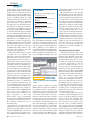
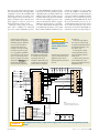
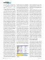
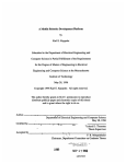
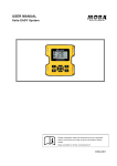
hands-on pr ject By David Marsh, Contributing Editor s industry insiders acknowledge, the need for speed drives FAST IS FREQUENTLY THE A KEY TO A PRODUCT’S At the highest echelons of the sport, competitive need frequently SUCCESS. BUT WHEN TIME- overrides considerations, such as cost and long-term return on in- SCALES ARE SERIOUSLY vestment, that typify mainstream commercial projects. In particu- SHORT, IT’S VITAL TO lar, cost frequently takes a back seat to the speed at which you can complete a new project. Even so, it comes as something of a surprise when commercial success depends on embedding intelligence and communications to take a development project from design brief to functional prototype within just two months. Without a suitable microcontroller to power the project from the outset, the prospects GETTING IDEAS TO MARKET CHOOSE FLEXIBLE DESIGN APPROACHES AND RESPONSIVE BUSINESS PARTNERS. HERE, A MOTORSPORT PROJ- every aspect of the motorsport industry—on and off the track. agement system. The microcontroller phase of the project calls for a plug-in board to provide a supervisory control and data-acquisition interface between the underlying power-control hardware and the car’s onboard systems. In an industry in which reliability is crucial, each stage of any project receives layers of testing that culminate in customer approval for a system to compete in championship ECT THAT INCLUDES THE Motorsport accelerates prototype design UNITED KINGDOM’S FIRST APPLICATION OF A BRANDNEW 32-BIT MICROCON- TROLLER COMES TO LIFE. At a glance ......................................22 Don’t neglect physical issues................................24 For more information ..................28 20 edn europe | July 2002 of success look distant and likely to force decisions that even the most pragmatic automotive engineers dislike. At times like this, normally reclusive hardware designers realise that capable, responsive, and, above all, willing business partners are key to success—as the story of “Project Hercules” demonstrates. Developed for sports-car and endurance-racing events, Project Hercules is an intelligent power-control system that actively manages all of a vehicle’s electrical circuits, including mission-critical channels, such as the engine-man- events. Partially for this reason, the initial phase of the power-control system comprises a modular design that can run as a stand-alone system. To provide the best reliability at the least risk, this standalone system is as simple as possible and uses as many tried-and-tested elements as is practical. The ability to run as a stand-alone system also suits cars that don’t carry central intelligence, providing cost savings to that market sector. Because the commissioning company, motorsport-system designer TJCW (Tony James Component Wiring), also serves ww.edn.com many industrial customers, it’s important for the project’s technology to be as reusable as possible. Accordingly, the stand-alone prototype of Hercules’ power-control system comprises two pc boards. A motherboard accommodates the power devices with their control elements and power supplies. A plug-in I/O signal-conditioning board provides the interface between the car’s various logic signals and switch-panel hardware. The motherboard makes extensive use of smart-power FETs from Infineon Technologies and International Rectifier. Together with external control logic, such FETs can reduce RDS(ON) power dissipation to negligible proportions to enable the packing density that vehicles such as Le Mans/GT prototype sports cars and endurance-spec touring cars require. Some smart-power FETs also provide an analogue feedback signal that’s proportional to output current (Reference 1). Given a suitable microcontroller and firmware, it’s possible to design a system that permits teams to run custom power-control strategies. For example, you might choose to temporarily disable the alternator to minimise engine power losses during a qualifying lap. FLEXIBLE I/O ENABLES MULTIPLE USES Photo courtesy Hitex The requirement to run as a stand-alone system or under processor control demands flexible input-signal switching. In stand-alone mode, inputs debounce switch-panel hardware and protect the downstream logic. In processorcontrol mode, tristate logic disconnects almost all input switches as serial-communication links assume control; few inputs, such as the park-ground signal that controls the wiper’s automatic-parking mechanism, remain connected. Further, most cars require circuits such as the engine-management system to be present with the master-switch positive supply, the ignition-on supply, or both, with no dedicated external switching. Regardless of the condition that enables each circuit in the end user’s application, designfor-test considerations demand independent hardwareand software-channel control to support automatic-testand-calibration routines. Finally, because the initial switch architecture may be unable to accommodate all end-user applications without hardware revisions, changes must be inexpensive and easy to make. As a result, the I/O board is a low-cost module that can change without affecting other boards. Able to withstand continuous ⫾25V input levels and ⫾15-kV ESD strikes, Maxim’s MAX6818 octal switches protect sensitive logic from environmental conditions and provide a nominal 40msec debounce time (Reference 2). The chips consume a maximum of 20 A from a 5V supply and include undervoltage-lockout protection to guarantee reliable start-up operation. Better still, the MAX6818 includes input pullup resistors of 63 k⍀/channel. You might wonder whether a 63-k⍀ pullup is strong enough to work in a noisy automotive application, but no problems have been evident, even with the unshielded wiring that feeds Hercules’ signal inputs. The MAX6818 also includes change-of-inputstate and tristate output controls that can simplify microcontroller interfacing. Importantly, the MAX6818 is specified for industrial-temperature-range operation and comes in 20-pin SSOPs that occupy less than 8⫻8 mm of pc-board space—and all for less than €3 (1000). The MAX6818s feed several PLDs (programmable-logic devices) that gate input-switch signals with status information, such as whether the ignition is on. The PLDs also provide the tristate interface that allows the processor board to assume executive control. In the initial design, the PLDs were Atmel’s ATF16V8CZ devices, which have very low average power consumption, helping to constrain Hercules’ full-load internal temperature rise to around 20⬚C. Costing around €2.50 (100), such “zero-power” PLDs employ input-transition-detection circuits that switch the device from active to standby mode after about 75 nsec of inactivity. In standby mode, the device turns off its internal fuse array to reduce power consumption from around 100 mA to some 25 A, while pin-keeper circuits maintain stable I/O conditions. This theory sounds fine, but in practice, some PLD outputs failed to track their inputs. Further analysis reveals that a slowly changing gating signal fails to wake the devices out of standby to update the output states; however, even sharpening this signal in a Schmitt trigger fails to provide reliable operation within the Hercules application. Substituting Cypress low-power PLDs (PALCE16V8L) provided an interim fix. But each of these parts consumes around 40 mA of quiescent current, which is similar to the current that the entire motherboard requires! Today’s approach routes a 250-Hz clock signal to each zero-power PLD to guarantee that it updates correctly. But a far better option that’s under evaluation may substitute July 2002 | edn europe 21 www.edn.com hands-on pr ject a single device from the Xilinx CoolRunner XPLA3 family, whose members provide 32 to 512 macrocells and 36 to 260 I/O pins. Suggested by PLD expert Arthur Wright, principal of First Time Designs, CoolRunner PLDs are fully CMOS structures that don’t rely on input-transition techniques or dedicated power-down pins to reduce quiescent consumption to less than 100 A. Running from a 3.3V supply, the 5V I/O-tolerant XPLA3-series includes JTAG-port in-system programmability to minimise pc-board rework and redesign. Available now, the midrange XCR3128XL offers 128 macrocells and 108 I/O pins in a 144pin TQFP for around €11 each from the Xilinx Web site (see sidebar “For more information”). If you’re prepared for a 60-Mbyte download, you can download the ISE WebPack design tool set for free. Also notice that Xilinx now offers the CoolRunner-II family, which is optimised for 1.8V operation to suit wider portable product applications. Other I/O-board functions include controlling the car’s indicator and wash/wipe systems. In a conventional vehicle, timer relays control these systems, but this approach can’t meet TJCW’s requirement to remove inelegant peripherals from the wiring loom’s structure. In stand-alone mode, an AT90S2313 microcontroller from Atmel’s AVR family drives the indicator and wash/wipe logic; in processor-control mode, the I/O pc board’s ability to cede control means that teams can experiment with alternative wash/wipe strategies to suit differing climatic conditions. The AT90S2313 is a 20pin device that has 15 independently programmable I/O lines, of which three serve in-system programming needs. (An external multiplexer can preserve I/O pin count.) On-chip memory comprises 128 bytes of RAM and 2 kbytes of flash, together with 128 bytes of EEPROM that you can use to store calibration constants. Other features include an analogue comparator, 8- and 16-bit timer/counters with programmable clock prescalers, a full-duplex UART, and internal and external interrupt sources. The catalogue distribution price is around €8 (250). Atmel’s decision to support the AVR family from the outset with a free development environment and low-cost tools, such as the ICE200 ICE (in-circuit emulator), proved decisive for another project in 2000. For around €200, you get a 22 edn europe | July 2002 AT A GLANCE 컄 Small-volume projects emphasise speed and flexibility over cost. 컄 Enthusiastic partners are key to meeting deadlines. 컄 BDM/OCDSs halve tool-chain costs. 컄 Complex 32-bit microcontrollers can simplify design. 컄 Don’t ignore potential hardware-layout issues. real-time ICE that nonintrusively emulates most AVR parts at full speed using a bond-out version of the AVR core. The ICE comes as standard with a variety of pods to suit eight- to 40-pin DIL devices, and an SMD kit is now available for around €120. Third-party AVR software support includes the QuickBasic-like Bascom compiler from MCS Electronics for around €80, and Imagecraft’s opti- Getting this Tasking CrossView debugger screen is the first step to TriCore development success. Figure 1 mising ANSI-C compiler for around €500; evaluation versions are available at the companies’ Web sites. You can download the latest versions of Atmel’s AVR Studio suite from the company’s Web site or from the AVR Forum at www.avrfreaks.net. Of course, the microcontroller landscape has moved on, and a feasibility study today may favour another vendor. Notably, some Microchip parts now have JTAG debugging capabilities and low-cost ICE support to complement competitive software tools. The recently announced PIC18xxx family includes members such as the PIC18F458, which features a CAN version 2.0B port to supplement the chip’s 32 kbytes of flash and typical microcontroller peripherals—all for around €7 (100). The I/O board carries three PC-104 stack-through connectors that plug into the motherboard, with the processor board becoming the top board in a threepc-board stack. A custom-made enclosure and pc-board mounting hardware ensure that the composite assembly withstands the mechanical shock loadings that plague competition vehicles. Harwin’s €3 (100) PC-104 connectors are very rugged and specified for ⫺55 to ⫹105⬚C operation. With mechanical detailing by ex-Lotus Formula One designer Martin Ogilvie at Prototype Car Designs, the Hercules enclosure provides around 0.5 mm clearance between the lid and the top connector. This clearance ensures that even if the pc-board mounts break, the boards can’t separate and should survive and work through an accident situation. CHOOSING PROCESSORS ISN’T TRIVIAL With the stand-alone prototype complete and with encouraging bench- and field-test results available, project management approved the second development phase that requires processor control. Here, the real pressure started when a customer requirement to run the processor-controlled Hercules in an event-specification car demanded that the first prototype appear within just eight weeks. Worse, this period straddled Christmas and New Year’s. Although this situation is normal within motorsports, most other industries simply aren’t geared up to respond with similar alacrity. In a marketplace in which volumes are low and timescales are uncompromisingly short, it’s imperative to select partners who will unquestioningly provide support. It’s therefore a tribute to all the project’s commercial partners that the first prototype came to life with around 12 hours to spare. The first obstacle, choosing a microcontroller, is always challenging. According to a recent survey, engineers rate these criteria as their first thoughts when choosing new processors: available software tools (66.9%); price (50.7%); available I/O (39.5%); available hardware tools (35.2%); and code compatibility (26.7%, Reference 3). Hercules has slightly different perspectives. With almost 200 signals to handle, the project has demanding I/O capabilities that include 32 channels of ADC, two CAN (controllerwww.edn.com hands-on pr ject area-network) ports, and at least one serial port. Industrial or extended operating-temperature range is essential but comes as standard with devices in this market segment. And although available development tools are a prerequisite for any project, processor price and code compatibility are virtually irrelevant in this project’s context. Crucially, the processor and its support circuitry must fit within the limited space that Hercules offers and contribute as little as possible toward power dissipation (see sidebar “Don’t neglect physical issues”). These considerations suggest a processor with extensive I/O and sufficient onchip memory to run the application without requiring any peripherals other than power supplies and support circuits. Hercules is undemanding of computational power, but reliability is key, so the processor must include comprehensive error-trapping mechanisms. Together, these requirements suggest a 32-bit machine that carries the memory, I/O, and reliability-enhancing features, but in which the computational power is wasted. The guiding principle of “simplest is best,” together with familiarity with various 68x and x86 architectures, suggests that microcontrollers such as Infineon’s SAB167CS and Motorola’s MC68376 may suit the need. Each of these devices DON’T NEGLECT PHYSICAL ISSUES the event, four signal layers and With today’s emphasis on hardcopper to define the land area 6-thou (0.15-mm) track-andware integration and structured (FFigure B). software design, it’s easy for Amkor supplies the TC1775B’s space rules wouldn’t allow the Pulsonix pc-board-design packdevelopment projects to relepackage, and the company’s age’s autorouter to complete the gate mundane issues, such as original information suggests board’s routing. Bob Williams, physical circuit layout. Although that SMD pads improve reliabilimarketing director at Pulsonix, PC-104 connectors ideally suit ty (RReference A). Inspecting the rescued this situation using the layout of Hercules motherTriBoard’s pc board suggests The initial Figure A Zuken’s Cadstar Route Editor boards, their central arrangethat this board uses SMD pads, TriCore autorouter. ment challenges the processor supporting the decision to use board occupies as much area as “If Route Editor can’t route it, board and its various buses and possible and includes a SMD technology. However, a nothing can,” says Williams. peripherals. The limiting factors later Amkor document suggests prototyping area for those that NSMD pads are as much as Realistically, more time and for the project’s processor pc afterthought-engineering another approach should allow 3.1 times more reliable than board combine a maximum out- exercises. the Pulsonix router to succeed. SMD (RReference B). You also line of 230⫻135 mm with the pins that occupy the four outer necessity for an autorouter to Then, using what sales manager need to consider the routing connect each of the 192 connec- rows of the 1.27-mm-pitch, Philip King calls its heroic turnissue: Motorola’s AN1231 applitor pins. As always, it’s desirable 23⫻23-pin package. (The cencation note shows that 1.27-mm- around-time service, Newbury that the production version of tral 5⫻5-pin matrix carries pitch SMD pads restrict trackElectronics fabricated, assemthe pc board is as small as pospower and ground connections and-space rules to 6 thou (0.15 bled, and delivered the board sible and occupies the minito the processor’s 2.5V core.) mm) compared with 8 thou within a week. Newbury also mum number of layers using (0.20 mm) for NSMD types. Other issues include choosing hand-masked the SMD pads commodity track-and-spacing Because many pc-board-design SMD (solder-mask-defined) or that provide perfect connectivity rules—say, eight layers maxipackages apply global clearances (FFigure C). NSMD (non-solder-maskmum and 6-thou (0.15-mm) for the solder-resist mask, it’s defined) pads to connect the Other hardware lessons rules. But the prototype boards also easier to implement NSMD package to the board. Although include the desirability of adding conservatively consume every pads. Otherwise, you may need NSMD pads follow the convenexternal SRAM to your protoavailable square mil and pruyour pc-board supplier’s help to tional space between copper type TriCore design. Without dently include a wire-wrap area land and the surrounding solder mask the PBGA area. For these external SRAM, the Hitop (FFigure A). reasons, future PBGA designs mask, an SMD pad uses the debugger can’t download proInitial routing tests show that will use NSMD technology. In solder mask to overlap the grams to flash memory. You the best 16-bit microconthen need expensive hardtroller and peripheral ware just to flash a board. 25-MIL VIA PAD DIAMETER combination requires far Alternatively, build a sim14-MIL DRILLED-VIA DIAMETER (12-MIL FINISHED DIAMETER) more layout effort than a ple “wiggler” to interface a 23-MIL SOLDER-MASK8-MIL TRACE WIDTH more highly integrated PC’s parallel port with the OPENING DIAMETER 23-MIL SOLDERPAD DIAMETER device, such as the 16-pin OCDS-1 header on 4-MIL SOLDER-MASK 4-MIL SOLDER-MASKOVERLAP TC1775B. Also, using the your target (FFigure D). TO-PAD CLEARANCE 35.4 MILS TC1775B eases circuit Evaluation software such 31-MIL SOLDER3.1-MIL SOLDER-MASK design, and there are as PLS’ elegant Universal PAD DIAMETER OPENING DIAMETER (b) (a) fewer parts to procure. Debug Engine can then But with no experience in program the target’s flash. BGA technology, the Compare non-solder-mask-defined pads (a) with solder-mask- For around €3000, Figure B biggest design challenge HighTec’s Gnu C/C⫹⫹ defined pads (b), which employ the pc board’s solder-resist involves escaping the 304 mask to define the BGA’s land areas. compiler and the PLS 24 edn europe | July 2002 www.edn.com has most of the features that the application demands and, with appropriate peripherals, can meet the remainder. But remaining questions concerning toolchain support and pc-board space require test routing to prove. Because toolchain support is easier to assess in a limited timescale, it takes priority. Although a huge range of development aids is available for Motorola processors, such as P&E Microsystems’ Universal Access Device complete a powerful but affordable development system. Without a GUI or an IDE, the Infineonsponsored port of the Gnu compiler is no thing of beauty, but HighTec stresses the product’s cross-platform capabilities. If you build a Linux PC, you can access a superb range of tools for free to support Gnu’s native environment (RReference C). For the Windows environment, 2Step’s principal programmer, less-than-€500 BDM (background-debug-mode) tools, the general perception is that Motorola serves high-volume sales and that support for low-volume projects is patchy. Conversely, experience with Infineon reveals a highly responsive company, but the full tool chain to support SAB167CS development is costly. Phytec’s starter-kit board for the single-CAN port SAB167CR derivative costs around €215, and the bundled evaluation version of Keil’s C-compiler is a joy to use. But, because the SAB167 is a traditional 166 machine, you need a conventional bondout processor ICE for emulation, and the tool-chain costs for a full-blown project quickly approach €12,000. You also need the space around the processor to accommodate the ICE connection system. It’s worth noting that later processors, such as the C161U and C165UTAH, carry Infineon’s OCDS (on-chip debug sys- Figure C Inspection X-ray photos show that the PBGA perfectly connects with the pc board’s SMD pads. Steve Robinson, believes that it’s minimal work to provide a user-friendly front end in VisualBasic. Hardwarewise, the compiler cannot currently support the TriCore’s peripheral120 control processor, but the basic chip is so powerful that many applications won’t need to offload peripheral control from the core. References A. Mescher, Paul, “Applications notes on surface mount assembly of Amkor/Anam PBGA and SuperBGA packages,” Amkor, October 1995. B. Syed, Ahmer, “Surface mount requirements for advanced packaging solutions,” Amkor, 2000. C. Marsh, David, “Tools ease Linux development,” Test & Measurement World, April 2001, www.tmworld.com. VCC 74LVT16244MTD TDI 82 TMS 82 *TRST 82 *BRK_IN *PORST 10k *OE1 O0 O1 GND 02 03 VCC 04 05 GND 06 07 08 09 GND O10 O11 VCC O12 O13 GND O14 O15 *OE4 82 82 ZHCS1006 *OCDS_E 82 TCK 82 VCC 2.2k 10 nF GND *OE2 I0 I1 GND I2 I3 VCC I4 I5 GND I6 I7 I8 I9 GND I10 I11 VCC I12 I13 GND I14 I15 *OE3 10k 10k 10k 10k VCC 47 3.3 nF 1 2 VCC TDO 4 GND CPU_CK TDI 3 5 7 *TRST 9 TCK 11 *BRK_IN 13 NC 15 Figure D www.edn.com 10k NC GND 5TMS 3 5TCK 4 5*TRST 5 5*BRK_IN 6 5*PORST 7 5*OCDS_E 8 5*BRK_OUT NC 10k 14 2 NC 15 16 17 NC NC 18 19 20 21 9 22 10 23 11 5TDO GND 1 5TDI 10k 47 24 12 NC VCC 25 13 25-WAY D CONNECTOR GND GND NOTE: SEE WWW.2STEPLIMITED.CO.UK FOR FREE PC-BOARD-DESIGN FILES. 16-PIN, DUAL-ROW, 1-IN. HEADER TMS 10k TDO GND 6 GND 8 *PORST 10 *BRK_OUT *BRK_OUT 3.3V VCC 12 GND 14 *OCDS_E 16 KEYWAY 5V 400W 100 nF 33 F 100 nF GND With appropriate driver software, a simple hardware wiggler provides a low-cost method of programming target flash memory. July 2002 | edn europe 25 hands-on pr ject tem), which works via the JTAG port, lowering midrange tool-chain costs to around €4500 and reducing ICEconnection requirements to a simple header. 32-BIT CS REPRESENT VALUE FOR MONEY For low-volume projects for which unit cost isn’t key, the relative value that BDM/OCDS tools provide, together with the advantages that a top-flight 32-bit microcontroller offers, are compelling. Another argument reasons that you can never have enough computing power and that what you don’t use today, you’ll need for another project. Lastly, if you’re going to commit to a new architecture, get the best futureproofing possible. These observations focus attention on Motorola’s MPC555 PowerPC and Infineon’s TC1775B TriCore, which target automotive applications. Both devices partially fulfill Hercules’ I/O demands and add a plethora of features that are immediately useful and safeguard future needs. Of these two, the MPC555 initially looked most attractive; the device carries sufficient on-chip flash to fulfill the application’s needs. The TC1775B requires external code memory. The MPC555 features a 40-MHz core with a floating-point unit, 448 kbytes of in-system-programmable flash, 26 kbytes of static RAM, and a memory-protection unit. It also offers two CAN 2.0B ports, 32 analogue inputs, and a flexible I/O system. Two timer/processor units and a multichannel serial module further suit Hercules. And, you can get started with the MPC555 using very low-cost tools, such as Intec Automation’s development board kit, which costs around €1000, including P&E’s BDM debugger and the freeware Gnu C/C⫹⫹ compiler. But, although the MPC555 has been in production for some time, distribution enquiries reported a 12-week leadtime, effectively taking the device out of contention. Further enquiries also suggest that the MPC555 has the reputation of being very hard to program. Clearly, such user perceptions are highly subjective. Alternatively, the TC1775B derivative of Infineon’s TriCore architecture is a brand-new chip and was qualified only this year, meaning that there was no distribution stock. But Infineon’s UK microcontroller products manager, Wendy Walker, approached TriCore product manager Bjoern Steurich in Munich to source the development samples that al- 26 edn europe | July 2002 lowed the project to proceed. With the exception of having no on-chip flash, the 329-pin TC1775B is a better fit for Hercules than the 272-pin MPC555 because the TC1775B’s PBGA package offers yet more available I/O. The TriCore carries a range of peripherals, including two CAN ports that augment the chip’s main core, a DSP block, and a peripheral-control-processor subsystem. On-chip user memory comprises 32 kbytes of data SRAM, 32 kbytes of code scratchpad SRAM, and 8 kbytes of SRAM, making it suitable for battery backup. This last feature is useful to maintain control-state settings between test runs, when it’s likely that technicians will disconnect the car’s master-switch power. And from a programmer’s perspective, it’s relatively easy to port 166 code onto a TriCore, providing a familiar entry point. In production quantities, the TC1775B’s guide price is around €20 (50,000); low-volume distributor pricing is around €30 for a 162-piece reel. The TriCore also has an encouraging choice of ICE and similar tools from vendors including Abatron, Ashling Microsystems, Hitex, Lauterbach, PLS, and Signum Systems. Compiler vendors include Green Hills Software, HighTec, and Tasking; yet more tools appear at Infineon’s Space Program Web site at www.spacetools.com. Most hardware tools and software debuggers exploit the TC1775B’s OCDS Level 1 capability that provides access to on-chip hardware and runtime control via a 16-pin header (Reference 4). But top-spec tools from vendors such as Ashling, Hitex, Lauterbach, and PLS can access a 40-pin OCDS Level 2 connector to support real-time trace reconstruction. Level 1 suits applications such as Hercules that run few time-critical processes from a simple scheduler, such as a block of analogue-to-digital The Hitex Hitop debugger intuitively views and reports processor and peripheral conditions. Figure 2 conversions. But with an eye to future projects, OCDS Level 2 capability suits demanding applications such as powertrain management with multiple timecritical processes running under RTOS supervision. Infineon’s TriBoard kit is the starting point for TC1775B development. Made by TQ Components, the kit comprises a 100⫻160-mm pc board that carries the processor, 4 Mbytes of burst-mode flash, and 1 Mbyte of SRAM, together with clock sources and power supplies. There’s an array of I/O connections that feed four 80-pin headers, into which you can plug optional breakout boards for easy access to signal lines. The board communicates with a PC using a “wiggler” parallel-port interface to its OCDS-1 system; a DB9 connector hosts RS-232 serial communication. Separate headers carry the second RS-232 port and signals to both CAN ports. Two further headers provide access to the OCDS-1 and OCDS-2 lines to suit external hardware tools. The starter-kit CD furnishes comprehensive documentation that usefully includes the circuit diagrams. You also get three manuals that describe the TriCore’s architecture, system units, and peripheral units. Software support includes Infineon’s DaVE (digital application virtual engineer), which automates processor setup scripts; evaluation versions of the Hitex Hitop debugger and Tasking’s C-compiler; and the Space Program development-tools-sampler CD. Available from Hitex, the kit includes an ac adapter and costs around €420; a set of four breakout boards costs €120. SUCCESS REWARDS PATIENCE When you’re armed with the TriBoard kit, you’ll need some patience to get up and running. First, locate all the software components that you need. After some experimentation, the most straightforward strategy loads the Hitop debugger and the Tasking demo compiler from the Hitop debugger-starter-kit CD. According to the documentation, you need a Win NT/2000 machine to support the wiggler driver, but a Win 98 machine has been running it without protest. Notice that the Hitop setup process immediately fails if you don’t have a sound card in your machine, so run Setup.exe from the hitop_tc1775 subdirectory. Problems such as this one waste time, and there are several others to overcome. For example, to preserve default paths, install the Taskwww.edn.com hands-on pr ject ing software in its default directory. If you then follow the instructions in the TriBoard manual under “Starting a new Tasking EDE project,” you should compile, upload, and run the getting-started project that’s on Infineon’s Starter Kit CD. When you see the Tasking CrossView debugger display and the RS-232 activity monitor in Figure 1, you’ve overcome the first hurdle. The Hitop debugger is more powerful than CrossView but tricky to get going, despite some useful notes (Reference 5). In particular, the View-User facility that displays the processor’s system and peripheral units is highly intuitive, with mappings that closely reflect the TC1775B’s user-manual conventions (Figure 2). Tasked with writing the prototype code for Hercules, 2Step Ltd’s principal programmer, Steve Robinson, found that several support calls resolved issues such as which files Hitop and the Tasking demo need to run and the location of these files. But when you’re successful, Hitop facilitates uploading programs to the TriBoard’s SRAM or programming its flash. Notice that running programs from flash can be as much as three times faster than SRAM due to the TC1775B’s support for burst-mode memories (AMD’s Am29BL162CB on the TriBoard). Because Hercules is the first TriCore application to surface in the United Kingdom, it’s not surprising that there were some “teething” troubles. Thanks to assistance from Infineon field application engineer Karl Smith, the board’s hardware worked perfectly the first time. But commissioning the tool chain was challenging. The demo version of the Tasking compiler is Version 1.3, but the full product is currently Version 1.4, which has substantial differences that seemingly include incompatibility with Infineon’s DaVE software. (The Web site now suggests that Version 1.5 is shipping.) The defacto standard for TriCore development, Tasking’s product is doubtlessly technically excellent, but it is abstruse. Amazingly, for a compiler that targets embedded applications, no example of how to use the TriCore’s peripherals or subsystems exists. Robinson of 2Step also observes that to further automate the building process, the later version obscures the locations of key files. Until you understand what’s going on, this situation creates havoc. Enter Hitex UK’s TriCore expert, Mike Beach. One Saturday last February, he visited 2Step’s lab to configure the tool chain, build the project, and download the object code that sent Hercules to its critical test debut. The basic OCDS-1 version of the Hitex Tanto-TC costs around €3800, and the Tasking compiler costs €4800, including 12 months of updates. For more demanding applications, the Tanto-TC with its trace unit costs around €8700 to exploit the processor’s OCDS Level 2 features.왏 References 1. Marsh, David, “Smart You can reach power switches simplify Contributing Editor David low-voltage systems”, EDN Marsh at Europe, December 2001, pg forncett@ btinternet.com. 27. 2. Levya, Phil, “Interfacing switches and relays to the real world in real time”, EDN, June 7 2001, pg 135. 3. ImObersteg, Glenn, “Viewpoint: Looking Forward,” Contact, May 2001, pg 2. www.spacetools.com. 4. Marsh, David,“Auto industry drives embedded boundary-scan debugging,” EDN Europe, August 2001, pg 22. 5. “Getting started with performance testing the TC1775B using the TriBoard and Hitop,” Hitex,www.tricoretoolbox. com. FOR MORE INFORMATION... For more information on products such as those discussed in this article, go to www.edn-info.com and enter the reader service number. When you contact any of the following manufacturers directly, please let them know you read about their products in EDN Europe. Abatron www.abatronag.ch Enter No. 420 Green Hills Software www.ghs.com Enter No. 426 Hitex www.hitex.com Enter No. 432 Lauterbach www.lauterbach.com Enter No. 438 P&E Microsystems www.pemicro.com Enter No. 444 Tasking www.tasking.com Enter No. 450 AMD (Advanced Micro Devices) www.amd.com Enter No. 421 Farnell Components www.farnell.com Enter No. 427 Imagecraft www.imagecraft.com Enter No. 433 Maxim www.maxim-ic.com Enter No. 439 Phytec www.phytec.com Enter No. 445 Tony James Component Wiring (TJCW) www.tonyjames.co.uk Enter No. 451 First Time Designs [email protected] Enter No. 428 Infineon Technologies www.infineon.com Enter No. 434 MCS Electronics www.mcselec.com Enter No. 440 PLS www.pls-mc.com Enter No. 446 Gnu www.gnu.org Enter No. 429 Intec Automation www.steroidmicros.com Enter No. 435 Microchip www.microchip.com Enter No. 441 Prototype Car Designs [email protected] Enter No. 447 Harwin www.harwin.com Enter No. 430 International Rectifier www.irf.com Enter No. 436 Motorola www.mot-sps.com Enter No. 442 Pulsonix www.pulsonix.com Enter No. 448 HighTec EDV-Systeme www.hightec-rt.com Enter No. 431 Keil www.keil.com Enter No. 437 Newbury Electronics www.newburyelectronics.co.uk Enter No. 443 Signum Systems www.signum.com Enter No. 449 Amkor Technology www.amkor.com Enter No. 422 Ashling Microsystems www.ashling.com Enter No. 423 Atmel www.atmel.com Enter No. 424 Cypress Semiconductor www.cypress.com Enter No. 425 TQ Components www.tqc.de Enter No. 452 2Step Limited www.2steplimited.co.uk Enter No. 453 Xilinx www.xilinx.com Enter No. 454 Zuken www.zuken.com Enter No. 455 SUPER INFO NUMBER For more information on the products available from all of the vendors listed in this box, enter no. 456 at www.edn-info.com. 28 edn europe | July 2002 www.edn.com