1
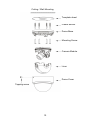
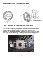
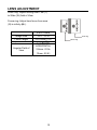
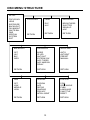
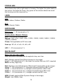
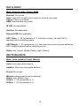
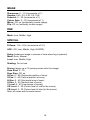
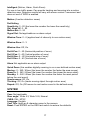
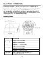
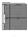
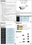
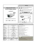
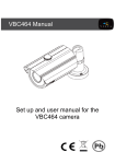
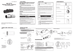
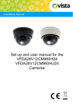
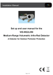
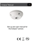
Installation Manual Set up and user manual for the VFD28V12WDR Camera i Before You Begin Read these instructions before installing or operating this product. Note: This installation should be made by a qualified service person and should conform to local codes. This manual provides installation and operation information. To use this document, you must have the following minimum qualifications: A basic knowledge of CCTV systems and components A basic knowledge of electrical wiring and low-voltage electrical connections Intended use Only use this product for its designated purpose; refer to the product specification and user documentation. Customer Support For assistance in installing, operating, maintaining and troubleshooting this product refer to this document and any other documentation provided. If you still have questions, please contact Norbain Technical Support and Sales: Norbain SD Ltd, 210 Wharfedale Road, IQ Winnersh, Wokingham, Berkshire RG41 5TP, England. UK +44 (0) 118 912 5000 Vista Technical Helpline: +44 (0) 118 912 5125 Note: You should be at the equipment and ready with details before calling Vista Technical Support. Conventions Used in this Manual Boldface or button icons highlight command entries. The following WARNING, CAUTION and Note statements identify potential hazards that can occur if the equipment is not handled properly: * WARNING: Improper use of this equipment can cause severe bodily injury or equipment damage. ** Caution: Improper use of this equipment can cause equipment damage. Note: Notes contain important information about a product or procedure. ii This apparatus is manufactured to comply with the radio interference. A Declaration of Conformity in accordance with the following EU standards has been made. The manufacturer declares that the product supplied with this document is compliant the provisions of the EMC Directive 2004/108/EC, the CE Marking Directive 93/68 EEC and all associated amendments. All lead-free products offered by the company comply with the requirements of the European law on the Restriction of Hazardous Substances (RoHS) directive: 2011/65/EU, which means our manufacture processes and products are strictly “lead-free” and without the hazardous substances cited in the directive. The crossed-out wheeled bin mark symbolizes that within the European Union the product must be collected separately at the product end-of-life. This applies to your product and any peripherals marked with this symbol. Do not dispose of these products as unsorted municipal waste. * This symbol indicates electrical warnings and cautions. ** This symbol indicates general warnings and cautions. NORBAIN SD LTD reserves the right to make changes to the product and specification of the product from time to time without prior notice. WARNINGS AND CAUTIONS: To reduce the risk of fire or electric shock, do not insert any metallic objects through the ventilation grills or other openings on the equipment. CAUTION CAUTION RISK OF ELECTRIC SHOCK DO NOT OPEN WARNING: TO REDUCE THE RISK OF ELECTRIC SHOCK, DO NOT REMOVE COVER (OR BACK). NO USER-SERVICABLE PARTS INSIDE. REFER SERVICING TO QUALIFIED SERVICE PERSONNEL. iii IMPORTANT SAFEGUARDS 1. READ AND RETAIN INSTRUCTIONS Read the instruction manual before operating the equipment. Retain the manual for future reference. 2. CLEANING Turn the unit off and unplug from the power outlet before cleaning. Use a damp cloth for cleaning. Do not use harsh cleansers or aerosol cleaners. 3. ATTACHMENTS Do not use attachments unless recommended by manufactured as they may affect the functionality of the unit and result in the risk of fire, electric shock or injury. 4. MOISTURE Do not use equipment near water or other liquids. 5. ACCESSORIES Equipment should be installed in a safe, stable location. Any wall or shelf mounting accessory equipment should be installed using the manufacture's Instructions. Care should be used when moving heavy equipment. Quick stops, excessive force, and uneven surfaces may cause the equipment to fall causing serious injury to persons and objects. 6. VENTILATION Openings in the equipment, if any, are provided for ventilation to ensure reliable operation of the unit and to protect if from overheating. These openings must not be blocked or covered 7. POWER SOURCES The equipment should be operated only from the type of power source indicated on the marking label. If you are not sure of the type of power supplied at the installation location, contact your dealer. For equipment designed to operate from battery power, refer to the operating instructions. 8. GROUNDING OR POLARIZATION Equipment that is powered through a polarized plug (a plug with one blade wider than the other) will fit into the power outlet only one way. This is a safety feature. If you are unable to insert the plug fully into the outlet, try reversing the plug. Do not defeat the safety purpose of the polarized plug. Alternate Warning: If the equipment is powered through a three-way groundingtype plug, a plug having a third (grounding) pin, the plug will only fit into a groundingtype power outlet. This is a safety feature. Do not defeat the safety purpose of the grounding-type plug. If your outlet does not have the grounding plug receptacle, contact your local electrician. 9. CORD AND CABLE PROTECTION Route power cords and cables in such a manner to protect them from damage by being walked on or pinched by items places upon or against them. 10. LIGHTNING For protection of the equipment during a lightning storm or when it is left unattended and unused for long periods of time, unplug the unit from the wall outlet. Disconnect any antennas or cable systems that may be connected to the equipment. This will prevent damage to the equipment due to Lightning or power-line surges. 11. OVERLOADING Do not overload wall outlets and extension cords as this can result in a risk of fire or electric shock. iv 12. SERVICING Do not attempt to service the video monitor or equipment yourself as opening or removing covers may expose you to dangerous voltage or other hazards. Refer all servicing to qualified service personnel. 13. DAMAGE REQUIRING SERVICE Unplug the equipment from the wall outlet and refer servicing to qualified service personnel under the Following conditions: A. When the power supply cord or the plug has been damaged. B. If liquid has spilled or objects have fallen into the Unit. C. If the equipment has been exposed to water or other liquids. D. If the equipment does not operate normally by following the operating instructions, adjust those controls that are covered by the operating instructions as Improper adjustment for other controls may result in damage to the unit. E. If the equipment has been dropped or the casing is damaged. F. When the equipment exhibits a distinct change in performance. 14. REPLACEMENT PARTS When replacement parts are required, be sure the service technician uses replacement parts specified by the manufacturer or that have the same characteristics as the original part. Unauthorized substitutions may result in fire, electric shock, or other hazards. 15. SAFETY CHECK Upon completion of any service or repairs to the equipment, ask the service technician to perform safety checks to verify that the equipment is in proper operating condition. 16. FIELD INSTALLATION The installation of equipment should be made by a qualified service person and should conform to all local codes. 17. CAUTION THESE SERVICING INSTRUCTIONS ARE FOR USE BY QUALIFIED SERVICE PERSONNEL ONLY. TO REDUCE THE RISK OF ELECTRIC SHOCK DO NOT PERFORM ANY SERVICING OTHER THAN THAT CONTAINED IN THE OPERATING INSTRUCTIONS UNLESS YOU ARE QUALIFIED TO DO SO. 18. Use certified/Listed Class 2 power source only. CE COMPLIANCE STATEMENT WARNING This is a Class A product. In a domestic environment this product may cause radio interference in which case the user may be required to take adequate measures. v TABLE OF CONTENTS INTRODUCTION --------------------------------------------------------------------------------------- 7 CONTENTS OF PACKAGE ------------------------------------------------------------------------- 8 BASIC INSTALLATION ------------------------------------------------------------------------------- 8 TACT SWITCH OPERATION / SERVICE JACK ----------------------------------------------- 11 LENS ADJUSTMENT --------------------------------------------------------------------------------- 12 OSD MENU STRUCTURE --------------------------------------------------------------------------- 13 DEAD PIXEL CORRECTION------------------------------------------------------------------------ 18 DIMENSIONS ------------------------------------------------------------------------------------------- 18 SPECIFICATIONS ------------------------------------------------------------------------------------- 19 vi INTRODUCTION Camera Model Features: ● ● ● ● ● ● ● ● ● ● ● ● ● ● ● ● ● ● ● ● 1/3” Sony IMX238 CMOS 120dB Wide Dynamic Range (WDR) True Day/Night operation 1000TVL colour and monochrome resolution 2.8-12mm (F1.4-360) 2MP varifocal IR corrected lens 1.0Lux (Colour) / 0.5Lux (Monochrome) / 0.01Lux (Sens-up) @ F1.4 sensitivity Auto electronic shutter (1/50 to 1/60,000) and manual electronic shutter modes Day & Night – Auto, Colour, B&W OSD - On Screen Display (via tact switch) 3DNR (Digital Noise Reduction) AGC (Auto Gain Control) Auto and manual white balance modes BLC (Back Light Compensation) HLC (High Light Compensation - PWI) 16 Privacy zones 4 Motion detection zones with digital zoom Functions (Mirror, Flip, Digital Zoom, Quick Zoom Brightness, Sharpness, Contrast) Test Monitor Output (Service Jack) 12VDC operation Use Certified Listed Class 2 power source only. 7 CONTENTS OF PACKAGE Installation of the camera must be performed by qualified service personnel in accordance with all local and national electrical and mechanical codes. Carefully remove the colour camera and its accessories from the carton and verify that they were not damaged in shipment. The content of the package includes: 1. Camera 3. Instruction manual 5. DC Jack 2. Fixings 4. Template sheet BASIC INSTALLATION 1. Make mounting holes and cable hole in the place (ceiling) to which this dome camera is installed using the supplied template sheet. When using the mounting screws, Use the holes on template position "T1" Use the side knock-outs for cable entry [Template sheet] NOTE: it is not critical that the camera module is removed for installation so as long as care is used. 8 2. First remove the camera module by pulling down on the taps that hold the camera module in place [fig A] [fig A] [fig B] 3. Knock out the screw access holes (T1), this is can be done by using a Cross head screwdriver 4. Pull the video / power cables through the cable hole, then connect in the normal way 5. Attach the dome base to ceiling or wall using mounting screws, plastic anchors (If required, remove the side knock-outs for cable entry, make sure the video & power cables are properly arranged in the cable notch> 6. Insert the camera module, remove the liner 7. Adjust the camera module to the area you want to view, then adjust the zoom and focus to suit 8. Carefully fit the liner over the camera module so that it snaps into place [fig B] 9. Close the dome cover by rotating clockwise 10. Secure the dome cover using the tapping screw NOTES: If the 2.1mm jack adaptor is not used then please ensure the correct polarity is observed when 12VDC is being used. The terminals are colour coded to assist: Red = 12VDC / Black = 0V 9 Ceiling / Wall Mounting Template sheet Plastic anchor Dome Base Mounting Screw Camera Module Liner Dome Cover Tapping screw 10 MOUNTING ON A SINGLE GANG BOX Mount the dome base on the box with proper securing holes UK Single Gang Box Mounting holes available for the Single Gang Box TACT SWITCH OPERATION/SERVICE JACK The tact switch allows both navigation and changes to the OSD Menu. To enter into the OSD menu push centrally on the joystick and navigate using the up, down, left and right actions. If there is an arrow to the right of the menu function, this denotes that there is an accessible sub menu function. The white plug to the left is the service jack to allow setup of the camera without having to remove the main video cable (the service cable is available separately) 11 LENS ADJUSTMENT Zoom ring: Adjust setting from Tele (T) to Wide (W) field of View. Focus ring: Adjust lens focus from near (N) to infinity ( ). 2.8 to 12mm Image Size Focal Length Aperture Ratio 1/2.7’’ CCD 2.8-12mm 5% 1 : 1.4 5% HORIZONTAL Angular Field of View 2.8mm: 81.2 12mm: 22.6 12 Focus ring Zoom ring OSD MENU STRUCTURE SETUP FOCUS ADJ LENS EXPOSURE BACKLIGHT DAY&NIGHT WHITE BAL DNR SPECIAL SYSTEM EXIT FOCUS ADJ RETURN LENS EXPOSURE ELC ALC BRIGHTNESS SHUTTER SENS-UP AGC RETURN RETURN BACKLIGHT DAY&NIGHT WHITE BAL OFF HLC BLC WDR MODE IR LED ANTI-SAT EXTERN S/W AGC THRES AGC MARGIN DELAY AUTO AUTOEXT PRESET MANUAL RETURN RETURN RETURN DNR SPECIAL SYSTEM OFF LOW MIDDLE HIGH D-ZOOM ACE DEFOG SHADING PRIVACY INTELLIGENT COM. VIEW ANGLE CVBS LANGUAGE CAM TITLE RESET RETURN RETURN RETURN 13 FOCUS ADJ The columns from left to right assist in focusing. The higher the yellow scale on the column, the better the focus. Any green on the column shows how much the focusing could be improved by. LENS ALC Mode: Indoor, Outdoor, Deblur ELC Mode: Normal, Deblur EXPOSURE Brightness: 1 - 20 (increments of 1) Shutter (Auto / Manual / Flicker) Auto: Lens adjusts automatically Manual: 1/50, 1/100, 1/240, 1/500, 1/1000, 1/2000, 1/4000, 1/8000, 1/16000, 1/30000, 1/60000 Flicker: Not applicable as DC lens used Sens-up: Off, x2, x4, x8, x16, x32, x50 AGC: 1 - 20 (increments of 1) BACKLIGHT Mode: Off, HLC, BLC, WDR Note: only one of the above can be applied at any one time HLC (Globally applies Peak White Inversion to the image) Level: 1 - 20 (increments of 1), the lower the number the more HLC is applied Mode: All Day, Night only BLC (Applies a user defined area of Back Light Compensation to the image) H-Poz: 1 - 20 (increments of 1), changes horizontal position of BLC area V-Poz: 1 - 20 (increments of 1), changes vertical position of BLC area H-Size: 1 - 20 (increments of 1), changes horizontal size of BLC area V-Size: 1 - 20 (increments of 1), changes vertical size BLC area WDR (Globally applies Wide Dynamic Range to the image) Weight: Low, Middle, High 14 DAY & NIGHT Mode: External, Auto, Colour, B&W External: Do not use Auto: Uses AGC to switch from colour to mono & vice versa Colour: Colour only mode B&W: Monochrome only mode IR LED: Not applicable Anti-Sat: Not applicable External S/W: Not applicable AGC Thres: 1 - 20 (increments of 1), the lower number, the less AGC is required before switching occurs AGC Margin: 1 - 20 (increments of 1), the lower the number the less additional AGC margin is applied before switching occurs Delay: Low (3secs), Middle (6secs), High (10secs) WHITE BALANCE Mode: Auto, AutoExt, Preset, Manual Auto: Auto trace white balance AutoExt: Wide auto trace white balance Preset: Do not use Manual (manually set the white balance) Kelvin: Low, Middle, High R-Gain: 1 - 20 (increments of 1) B-Gain: 1 - 20 (increments of 1) 15 IMAGE Sharpness: 0 – 10 (increments of 1) Gamma: 0.45, 0.5, 0.55, 0.6, 0.65 Pedestal: 0 – 20 (increments of 1) Colour Gain: 0 – 20 (increments of 1) Mirror: Off, on (horizontally inverts image) Flip: Off, on (vertically inverts image) DNR Mode: Low, Middle, High SPECIAL D-Zoom: 1.0x - 8.0x (increments of 0.1) ACE: Off, Low, Middle, High (D-WDR) Defog (enhances image in scenes of view when fog is present) Mode: Auto, Manual Level: Low, Middle, High Shading: Do not use Privacy (apply up to 16 privacy zones onto the image) Zone Num: 0 - 15 Zone Disp: Off, on H-Poz: 0 - 60 (Horizontal position of zone) V-Poz: 0 - 40 (Vertical position of zone) H-Size: 0 - 40 (Horizontal size of zone) V-Size: 0 - 40 (Vertical size of zone) Y Level: 0 - 20 (Luminance of zones) CR Level: 0 - 20 (Colour level of red for the zones) CB Level: 0 - 20 (Colour level of blue for the zones) Note: all zones are the same colour 16 Intelligent (Motion, Alarm, Quick Zoom) For use in low traffic areas. Can provide tracking and zooming into a motion detection area. Detection results will vary with scene content / movement and does not work if WDR is enabled Motion (4 motion detection zones) Det.Setting Sensitivity: 0 - 20 (the lower the number the lower the sensitivity) Obj. Keep LV: 0 - 60 Motion Est: 0 - 20 Signal Out: Not applicable as no alarm output Window Tone: 0 - 6 (applies level of obscurity to non motion area) Window Zone: 0 - 3 Window Use: Off, On Det H-Poz: 0 - 60 (Horizontal position of zone) Det V-Poz: 0 - 40 (Vertical position of zone) Det H-Size: 0 - 60 (Horizontal size of zone) Det V-Size: 0 - 40 (Vertical size of zone) Alarm Not applicable as no alarm output Quick Zoom (this enables digitally zooming in on a user defined motion area) Moving: 0 - 240 / 60sec (the lower the number the faster the area moves) Zoom In: 0 - 240 / 60sec (the lower the number the slower the zoom state) Standby: 0 - 240 / 60sec (the lower the number the faster the reset period before the next event) Synchronous: Off, On Tracking: Off, On (tracks moving object through motion area) Repeat: Off, On (Off moves to next motion event in the defined area) SYSTEM Com: Not applicable View angle: Wide 4:3, Wide 16:9, Normal CVBS: PAL, NTSC Language: English Cam Title: Apply an 8 character name to the camera Reset: Push ENTER on the OSD tact switch to restore the defaults 17 DEAD PIXEL CORRECTION It is perfectly normal for a camera CCD / CMOS to have what is known as ‘dead’, ‘hot’ or ‘white’ pixels, develop over time and on occasion and these can be noticeable on the viewed image. These can be masked easily, without affecting the quality of the image with the DEFECT DET function. To access this, push and hold the joystick LEFT for approx 5 seconds, scroll DOWN to DEFECT DET then push ENTER (central push on the OSD tact switch). Once this has run the OSD text disappears from screen. DIMENSIONS Mounting Type Surface Type Thick t = 0.05 in (2.0 mm) Window Spec. Material = Polycarbonate Diameter = 3.15 in (80.0 mm) Thick t = 0.18 in (3.0 mm) Bottom Case Material = Polycarbonate Diameter = 3.98 in (101.2 mm) Cable Entry One(1) opening hole with grommet (3/4’’) Four(4) Side Knockouts 18 SPECIFICATIONS General Function Model Resolution Image sensor WDR Operation Total pixels Effective pixels Scanning Syst. Scanning Freq. Sync. system Video output S/N Ratio Lens Min. illumination OSD Control Electronic Shutter Backlight Day / Night AGC White Bal. Sens-up 3DNR Motion Det. Quick Zoom Privacy Brightness Gamma Digital Zoom Mirror Flip Title Language Power Consumption Power input Video output Temperatures Humidity Dims. (net) Dims. (gross) Weight Approvals Connections/other VFD28V12WDR 1000TVL (colour and monochrome) 1/3″ SONY IMX238 CMOS 120dB True day / night 1305(H) x 1069(V) 1305(H) x 1049(V) 2:1 Interlace PAL: 15.625KHz(H) x 50Hz(V) Internal 1.0Vp-p (75Ω, composite) 50dB (AGC off) f2.8 - 12mm (F1.4 - 360) 2MP IR Corrected 1.0Lux (colour), 0.5Lux (mono), 0.01Lux (mono & Sens-up) Tactile switch Auto or Manual (1/50 to 1/60,000 sec) Off, HLC (PWI), BLC, WDR Auto, Colour, B&W Off, On Auto, AutoExt, Manual Off, x2, to x50 Off, Low, Middle, High 4 areas 4 areas 16 zones 0 - 20 0.45 to 0.65 x1.0 to x8.0 Off, On Off, On Off, On (8 characters) English 12VDC (-10 to +15%) 1.6W (130mA) 2-pin terminal block with 2.1mm jack adapter BNC connector, Spot Out 0 to 40°C (operating) / -10 to 50°C (storage) 0 to 90% (non-condensing) 101.2(Φ) x 80.5 (H) mm 120 (W) x 135 (H) x 135 (D) mm 140g (net) / 400g (gross) CE & RoHS2: 2011/65/EU 19 20 VFD28V12WDR Manual / V1.0 / 2014-10-07 (subject to change without notice) 21