1
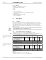
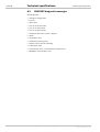
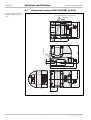
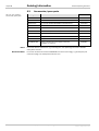
ADDENDUM OPERATING INSTRUCTIONS
S3000 PROFINET IO and
S3000 PROFINET IO OF
Safety laser scanner
en
Addendum Operating Instructions
S3000 PROFINET IO/IO OF
This document is protected by the law of copyright, whereby all rights established therein remain with the
company SICK AG. Reproduction of this document or parts of this document is only permissible within the limits
of the legal determination of Copyright Law. Alteration or abridgement of the document is not permitted without
the explicit written approval of the company SICK AG.
2
© SICK AG • Industrial Safety Systems • Germany • All rights reserved
8013291/YKY7/2015-04-20
Subject to change without notice
Addendum Operating Instructions
Contents
S3000 PROFINET IO/IO OF
Contents
8013291/YKY7/2015-04-20
Subject to change without notice
1
About this document.........................................................................................................5
2
On safety.............................................................................................................................6
2.1
Applications of the device.....................................................................................6
2.2
General safety notes and protective measures ..................................................6
3
Product description...........................................................................................................7
3.1
Special features ....................................................................................................7
3.2
Operating principle of the devices .......................................................................7
3.3
Input signals ..........................................................................................................8
3.3.1
Reset signals .......................................................................................8
3.3.2
Control signals for switching monitoring cases .................................8
3.3.3
Stand-by...............................................................................................9
3.3.4
Initialising ............................................................................................9
4
Mounting ..........................................................................................................................10
5
Electrical installation......................................................................................................11
5.1
System connection..............................................................................................11
5.1.1
Voltage supply ...................................................................................12
5.1.2
Network connection with RJ845-push-pull plug ...............................13
5.1.3
Network connection with SCRJ-push-pull plug (optical fiber) .........14
5.1.4
Local configuration connection ........................................................14
6
Configuration ...................................................................................................................15
6.1
Configuration PROFINET IO.................................................................................16
6.1.1
Reading the generic station description (GSDML) ..........................16
6.1.2
Configuring users ..............................................................................17
6.2
Configuration PROFIsafe.....................................................................................18
6.2.1
Setting the PROFIsafe address on the
S3000 PROFINET IO/IO8OF...............................................................20
6.2.2
Passivation and reintegration of the
S3000 PROFINET IO/IO8OF...............................................................21
6.3
Configuration of the S3000 PROFINET IO/IO8OF...............................................22
7
Diagnostics ......................................................................................................................23
7.1
Meaning of the status indicators .......................................................................23
7.1.1
Meaning of the LEDs.........................................................................23
7.1.2
Meaning of the 78segment display...................................................23
7.2
CDS (Configuration & Diagnostic Software) ......................................................26
7.3
Alarms..................................................................................................................27
7.3.1
I&M function (Identification & Maintenance function) ...................27
© SICK AG • Industrial Safety Systems • Germany • All rights reserved
3
Contents
Addendum Operating Instructions
S3000 PROFINET IO/IO OF
8
Technical specifications ................................................................................................ 28
8.1
Process image S3000 PROFINET IO/IO8OF Advanced ..................................... 28
8.1.1
INPUT................................................................................................. 28
8.1.2
OUTPUT.............................................................................................. 29
8.2
Process image S3000 PROFINET IO/IO8OF Professional ................................. 31
8.2.1
INPUT................................................................................................. 31
8.2.2
OUTPUT.............................................................................................. 32
8.3
PROFINET diagnostic messages ........................................................................ 34
8.4
Response times .................................................................................................. 35
8.5
Data sheet........................................................................................................... 36
8.6
Services supported............................................................................................. 37
8.7
Dimensional drawing S3000 PROFINET IO/IO8OF ............................................ 38
9
Ordering information ...................................................................................................... 39
9.1
Items supplied .................................................................................................... 39
9.2
Systems available............................................................................................... 39
9.2.1
S3000 PROFINET IO with RJ45 sockets.......................................... 39
9.2.2
S3000 PROFINET IO8OF with SCRJ sockets (optical fiber) ............. 39
9.3
Accessories/spare parts .................................................................................... 40
10 Annex................................................................................................................................ 41
10.1 EU declaration of conformity.............................................................................. 41
10.2 List of tables ....................................................................................................... 42
10.3 List of illustrations .............................................................................................. 42
4
© SICK AG • Industrial Safety Systems • Germany • All rights reserved
8013291/YKY7/2015-04-20
Subject to change without notice
Addendum Operating Instructions
About this document
Chapter 1
S3000 PROFINET IO/IO OF
1
About this document
This document is an original document.
This addendum is applicable for the S3000 PROFINET IO and S3000 PROFINET IO8OF safety laser scanners, in the following summarized as S3000 PROFINET IO/IO8OF. As far as the
connection variants differ, the respective product variant is named.
This addendum is applicable to the S3000 PROFINET IO/IO8OF safety laser scanner with
one of the following entries on the type label in the field Operating Instructions:
8013289
8013289/TL59
8013289/US26
8013289/YAX9
8013289/YKY7
Note
This document is part of SICK part number 8013289 (addendum operating instructions
“Safety Laser Scanner S3000 PROFINET IO and S3000 PROFINET IO8OF” in all available
languages).
This addendum only applies in conjunction with the original operating instructions
“S3000 Safety Laser Scanner” (SICK part number 8009791).
If not otherwise revised in this document, the information in the original operating
instructions applies, which relate to the S3000 Advanced or Professional safety laser
scanner.
For the configuration and diagnostics of these devices you require CDS (Configuration &
Diagnostic Software) version 3.6.4 or higher.
8013291/YKY7/2015-04-20
Subject to change without notice
© SICK AG • Industrial Safety Systems • Germany • All rights reserved
5
On safety
Chapter 2
Addendum Operating Instructions
S3000 PROFINET IO/IO OF
2
On safety
2.1
Applications of the device
The S3000 PROFINET IO/IO8OF safety laser scanner is used to protect persons and plant.
Stationary applications, e.g. for access or hazardous area protection, can be realised.
The safety level of the S3000 PROFINET IO/IO8OF corresponds to category 3 PL d
according to EN ISO 13 84981 and SIL2 according to IEC 61 508.
2.2
General safety notes and protective measures
Safety notes
WARNING
6
This addendum must be made available to the operator of the system, machine or the
vehicle where the S3000 PROFINET IO/IO8OF safety laser scanner is used, together with
the original operating instructions. The operator is to be instructed by qualified safety
personnel and is to read and follow the addendum; the operating instructions must also be
followed.
© SICK AG • Industrial Safety Systems • Germany • All rights reserved
8013291/YKY7/2015-04-20
Subject to change without notice
Addendum Operating Instructions
Product description
Chapter 3
S3000 PROFINET IO/IO OF
3
Product description
This chapter provides information on the special features and properties of the
S3000 PROFINET IO/IO8OF safety laser scanner. It also describes the properties and
functions that differ from the S3000 Advanced or Professional.
Please read this chapter before mounting, installing and commissioning the device.
3.1
Special features
protective field range 4 m, 5.5 m or 7 m
warning field range 49 m (20 m at 20 % remission)
S3000 PROFINET IO/IO8OF Advanced with 4 protective fields/warning fields (field sets)
S3000 PROFINET IO/IO8OF Professional with 8 protective/warning fields (field sets)
simultaneous protective fields with separate output information and separate feature
for resetting (see section 8.1 on page 28 or 8.1.2 on page 29)
direct fail-safe integration into PROFINET IO networks
supply connector with integrated configuration memory
connection types:
– S3000 PROFINET IO: RJ845 sockets for RJ845 push-pull plug
– S3000 PROFINET IO OF: SCRJ sockets for VARIOSUB push-pull SCRJ8plug
The S3000 PROFINET IO/IO8OF does not have any local inputs or outputs except the
interfaces for setting the parameters. All communication is via the PROFINET IO network.
3.2
Operating principle of the devices
PROFINET IO device
The PROFINET IO device is a remotely connected field device for installation in close proximity to the process. It expects the configuration from an IO controller/supervisor and
cyclically transmits its process data to the IO controller.
PROFIsafe for PROFINET
PROFIsafe defines how fail-safe devices (e.g. S3000 PROFINET IO/IO8OF) communicate
over a network with safety controllers (e.g. FPLC). It realises the safe communication via a
profile, i.e. using a special data format and a special protocol.
Device role
The S3000 PROFINET IO/IO8OF is an IO device.
It expects the configuration from an IO controller and cyclically transmits its process data
to the IO controller.
Device model
The S3000 PROFINET IO/IO8OF is available as a compact device.
8013291/YKY7/2015-04-20
Subject to change without notice
© SICK AG • Industrial Safety Systems • Germany • All rights reserved
7
Product description
Chapter 3
Addendum Operating Instructions
S3000 PROFINET IO/IO OF
Services supported
PROFINET IO with Conformance Class B
LLDP according to IEEE 802.1 AB
SNMP
MIB-II
cyclic IO communication
acyclic read/write services for communication via TCI interface
diagnostics alarms
TCP/IP communication via port 9000
support for MRP client
3.3
Input signals
3.3.1
Reset signals
If the safety laser scanner is operated using the “With restart interlock” function, then
after a protective field interruption and the subsequent clearing of the protective field, the
S3000 PROFINET IO/IO8OF requests a reset signal from the control system (Reset Required). The safety laser scanner reacts to an edge change on the reset signal from low to
high (not to the level).
The reset signal must be fail-safe (single failure proof)!
WARNING
3.3.2
Control signals for switching monitoring cases
You can switch between protective fields by switching monitoring cases.
Note
Tab. 1: Logical state 0 of the
control inputs in the process
image
The related control inputs A, B, C, D on theS3000 PROFINET IO/IO8OF Professional or A, B
on the S3000 PROFINET IO/IO8OF Advanced expect complementary signals.
Control input
Bits of the output byte 0 in
the process image (see
Tab. 10 on page 32)
Value of the bit
Tab. 2: Logical state 1 of the
control inputs in the process
image
A
B
C
D
0.0
0.1
0.2
0.3
0.4
0.5
0.6
0.7
1
0
1
0
1
0
1
0
Logical state
0
0
0
0
Control input
A
B
C
D
Bits in output byte 0 in the
process image (see
Tab. 10 on page 32)
Value of the bit
Logical state
0.0
0.1
0.2
0.3
0.4
0.5
0.6
0.7
0
1
0
1
0
1
0
1
1
1
1
1
Examples:
01011010 = valid value: A = 1, B = 1, C = 0, D = 0
11011010 = invalid value, input A is not set complementarily
8
© SICK AG • Industrial Safety Systems • Germany • All rights reserved
8013291/YKY7/2015-04-20
Subject to change without notice
Addendum Operating Instructions
Product description
Chapter 3
S3000 PROFINET IO/IO OF
3.3.3
Stand-by
The protective field and warning field outputs are deactivated by operating the
S3000 PROFINET IO/IO8OF in stand-by. The S3000 PROFINET IO/IO8OF remains in the
stand-by mode as long as the related input information is present (active high) (see
Tab. 10 on page 32).
3.3.4
Initialising
If the S3000 PROFINET IO/IO8OF is in the lock-out status, e.g. due to invalid values on the
inputs, the safety laser scanner can be initialised. During initialisation the device runs
through the boot sequence, similar to a warm start.
Once the cause of the error has been rectified, the device then starts to operate normally.
The safety laser scanner reacts to an edge change on the signal from low to high (not to
the level).
8013291/YKY7/2015-04-20
Subject to change without notice
© SICK AG • Industrial Safety Systems • Germany • All rights reserved
9
Mounting
Chapter 4
Addendum Operating Instructions
S3000 PROFINET IO/IO OF
4
Mounting
To calculate the safety distance and the size of the protective field when operated
horizontally or vertically in stationary or mobile applications, read the chapter “Mounting”
in the original operating instructions “S3000 Safety Laser Scanner” (SICK part number
8009791). Also pay attention to the dimensional drawings in section 8.7 on page 38.
10
© SICK AG • Industrial Safety Systems • Germany • All rights reserved
8013291/YKY7/2015-04-20
Subject to change without notice
Addendum Operating Instructions
Electrical installation
Chapter 5
S3000 PROFINET IO/IO OF
5
Electrical installation
Switch the power supply off!
The machine/system could inadvertently start up while you are connecting the devices.
WARNING
Ensure that the entire machine/system is disconnected during the electrical
installation.
5.1
System connection
The S3000 PROFINET IO/IO8OF is installed electrically using the supply connector and
using the two RJ845 ord SCRJ sockets.
Fig. 1: System connection
SCRJ sockets
Port 2 Port 1
Supply connector
RJ 45 sockets
Port 2 Port 1
System connection for RJ 45
Note
System connection for SCRJ (Optical Fiber)
With the push-pull plug connected the connection complies with enclosure rating IP 65.
– RJ-45: e.g. Phoenix VS-PPC-C1-RJ45-MNNA-PG9-4Q5, material no. 1608100
– SCRJ: e.g. Phoenix VS-PPC-C1-SCRJ-MNNA-PG9-A4D-C, material no. 1608032
With the provided cover the connection complies with enclosure rating IP 54.
8013291/YKY7/2015-04-20
Subject to change without notice
© SICK AG • Industrial Safety Systems • Germany • All rights reserved
11
Electrical installation
Chapter 5
Addendum Operating Instructions
S3000 PROFINET IO/IO OF
5.1.1
Voltage supply
The power is supplied via the supply connector. Lay the connecting cables through the
cable entry into the connector housing.
Fig. 2: Terminals on the
supply connector
Tab. 3: Terminal assignments on the supply
connector
Terminal
Note
Signal
Function
Wire colour (for the flying leads)
1
+24 V DC
Supply voltage
Brown
2
–
Do not use
–
3
0 V DC
Supply voltage
Blue
The external 24 V supply voltage may not exceed 40 V (SELV or PELV). This must be
ensured during the electrical installation.
As an option a pre-assembled supply connector with flying leads is available.
Fig. 3: Pre-assembled supply
connector
Part no.: 2049575
Additionally a pre-assembled supply connector with cable and external Y-piece is available.
This corresponds to a standardized push-pull power connector (industry standard).
Fig. 4: Pre-assembled cable
with Y-piece
Voltage supply
S3000
Part No.: 2049857 (on request)
12
© SICK AG • Industrial Safety Systems • Germany • All rights reserved
8013291/YKY7/2015-04-20
Subject to change without notice
Addendum Operating Instructions
Electrical installation
Chapter 5
S3000 PROFINET IO/IO OF
5.1.2
Notes
Network connection with RJ 45-push-pull plug
For the connection to the network you must use the push-pull plugs with a metal housing. With the push-pull plug connected the connection complies with enclosure rating
IP 65 (e.g. Phoenix VS8PPC8C18RJ45-MNNA-PG9-4Q5, material no. 1608100).
With the provided cover the connection complies with enclosure rating IP 54.
If the network is not connected to a following bus device, then a connection using a plug
is sufficient. It does not matter which of the two sockets is used. The unused socket
must always be protected with the provided cover (see Fig. 1).
Fig. 5: RJ 45-push-pull plug
(not included)
Tab. 4: Pin assignment on
the RJ 45 sockets
8013291/YKY7/2015-04-20
Subject to change without notice
Pin
Signal
PROFINET IO colours
1
TX+
Yellow
2
TX–
Orange
3
RX+
White
4
–
Do not use
5
–
Do not use
6
RX–
Blue
7
–
Do not use
8
–
Do not use
© SICK AG • Industrial Safety Systems • Germany • All rights reserved
13
Electrical installation
Chapter 5
Addendum Operating Instructions
S3000 PROFINET IO/IO OF
5.1.3
Notes
Network connection with SCRJ-push-pull plug (optical fiber)
For the connection to the network you must use the push-pull plugs with a metal housing. With the push-pull plug connected the connection complies with enclosure rating
IP 65 (e.g. Phoenix VS8PPC8C18SCRJ-MNNA-PG9-A4D-C, material no. 1608032).
With the provided cover the connection complies with enclosure rating IP 54.
If the network is not connected to a following bus device, then a connection using a
single plug is sufficient. It does not matter which of the two sockets is used. The unused
socket must always be protected with the provided cover (see Fig. 1).
Fig. 6: SCRJ-push-pull plug
(not included)
Notes
Without the usage of optical adapter plugs the maximum allowed cable length to the
next device is 50 m.
The maximum allowed line attenuation for the transmission link is 12 dB.
Pay attention to the mounting and wiring instructions of the manufacturer of the connectors and cables, in particular with regard to the number of bending radiuses.
Minimize the number of connectors in a connection cable, ideally to only two: one at the
S3000 PROFINET IO/IO8OF and another one at the FPLC.
Once the electrical installation is completed, determine the signal reserve of the connection cable using the CDS diagnostic function.
Use cables and connectors with low attenuation in order to obtain a signal reserve of
> 4 dB.
5.1.4
Local configuration connection
As a rule configuration is performed via PROFINET IO. A local RS8232 configuration connection is available on the S3000 PROFINET IO/IO8OF for configuration and diagnostics
directly at the device.
Fig. 7: Local configuration
connection
Local configuration connection
14
© SICK AG • Industrial Safety Systems • Germany • All rights reserved
8013291/YKY7/2015-04-20
Subject to change without notice
Addendum Operating Instructions
Configuration
Chapter 6
S3000 PROFINET IO/IO OF
6
Configuration
PROFINET IO network
Note
An MRP domain and a NameOfStation must be named as per the PNO specification V2.3.
For this reason take into account the following naming convention during the configuration
of your PROFINET IO network:
The identifier comprises one or more words.
These words are separated using a [.].
The total length of the identifier is 1 to 240 characters.
The word length is 1 to 63 characters.
The identifier uses the following syntax:
– Words comprise [a-z0-9-].
– Words do not start with [-].
– Words do not end with [-].
– The first word must not have the form port-xyz or port-xyz-abcde
(a, b, c, d, e and x, y, z = 0 … 9).
– Identifiers must not have the form n.n.n.n (n = 0 … 999).
Also take into account on naming an MRP domain:
The total length of the identifier must be 3, 7, 11, 15, 19, … characters.
S3000 PROFINET IO/IO OF
The configuration is performed in 3 steps:
1. Configuration PROFINET IO
2. Configuration PROFIsafe
3. Configuration of the S3000 PROFINET IO/IODOF
8013291/YKY7/2015-04-20
Subject to change without notice
© SICK AG • Industrial Safety Systems • Germany • All rights reserved
15
Configuration
Chapter 6
Addendum Operating Instructions
S3000 PROFINET IO/IO OF
6.1
Note
Configuration PROFINET IO
You can find an application and programming example for the configuration of the
S3000 PROFINET IO/IO8OF and an FPLC under the respective part number in the download
area on www.mysick.com.
6.1.1
Reading the generic station description (GSDML)
Before you can configure PROFINET IO for the first time for the S3000 PROFINET IO/IO8OF,
1)
you must add the generic station description (GSDML ) for the S3000 PROFINET IO/IO8OF
to the hardware catalogue in the network engineering tool, e.g. the SIMATIC Manager
(Siemens) for PROFINET IO.
Insert the DVD “CDS — Configuration & Diagnostic Software” contained in the package
into the DVD drive of the Notebook/PC, on which you have installed the network engineering tool of your FPLC.
The generic station description for the S3000 PROFINET IO/IO8OF can be found on the
DVD in the S3000 directory.
Follow the instructions of the online help or in the user manual of the network engineering tool for loading the generic station description.
Then the S3000 PROFINET IO/IO8OF appears in the hardware catalogue in the network
engineering tool under PROFINET IO > Additional Field Devices > Sensors > SICK.
Fig. 8:
S3000 PROFINET IO/IO OF in
the hardware catalogue
1)
16
GSDML = Generic station description based on XML.
© SICK AG • Industrial Safety Systems • Germany • All rights reserved
8013291/YKY7/2015-04-20
Subject to change without notice
Addendum Operating Instructions
Configuration
Chapter 6
S3000 PROFINET IO/IO OF
6.1.2
Configuring users
Every PROFINET IO field device, e.g. the S3000 PROFINET IO/IO8OF has a dedicated MAC
address. You will find the MAC address for the S3000 PROFINET IO/IO8OF on the sticker on
the rear of the I/O module (e.g. 00:06:77:02:00:A7).
In addition a PROFINET IO field device requires a unique system-specific device name. The
device name is used by the IO controller to define the IP address for the field device. The
IP address is defined in two steps:
1. You use the device name assigned to the S3000 PROFINET IO/IO8OF by the network
engineering tool, or you configure a unique system-specific device name with the aid of
the network engineering tool (e.g. SIEMENS SIMATIC Manager).
2. The IO controller assigns the IP address based on the device name.
How to define the name of the S3000 PROFINET IO/IO OF if necessary:
Double-click the symbol for S3000 PROFINET IO/IO8OF in the network engineering tool.
The Properties dialog box will open.
Select the General tab.
Enter the the device name for the S3000 PROFINET IO/IO8OF there.
Assign a new IP address.
Note
Device name and IP address must match the settings in the CDS.
Fig. 9: Properties of the
S3000 PROFINET IO/IO OF
8013291/YKY7/2015-04-20
Subject to change without notice
© SICK AG • Industrial Safety Systems • Germany • All rights reserved
17
Configuration
Chapter 6
Addendum Operating Instructions
S3000 PROFINET IO/IO OF
6.2
Configuration PROFIsafe
In slots in the network engineering tool, choose the command Object properties on the
context menu.
Fig. 10: Configuration
PROFIsafe, step 1
On the PROFIsafe tab configure the parameters for the S3000 PROFINET IO/IO8OF.
Note
See Tab. 5 for the parameters to be entered.
Fig. 11: Configuration
PROFIsafe, step 2
18
© SICK AG • Industrial Safety Systems • Germany • All rights reserved
8013291/YKY7/2015-04-20
Subject to change without notice
Addendum Operating Instructions
Configuration
Chapter 6
S3000 PROFINET IO/IO OF
Tab. 5: PROFIsafe
parameters for the
S3000 PROFINET IO/IO OF
Parameter
Meaning
Setting
F_SIL
Safety integrity level (NoSIL, SIL1 or SIL2) of
the S3000 PROFINET IO/IO8OF
Depending on
application
F_CRC_Length
Anticipated length of the CRC checksum in
the PROFIsafe telegram
3 Byte CRC
F_Block_ID
The value 1 in the parameter indicates that
the data set for the value of F_iPar_CRC is
extended by 4 bytes. You are not allowed to
change the parameter.
0
F_Par_Version
Implemented PROFIsafe version. You cannot
change this parameter.
1
F_Source_Add
PROFIsafe source address. Must be unique in
combination with the PROFIsafe destination
address and is assigned automatically.
1 to 65 534
F_Dest_Add
PROFIsafe destination address. Must be
unique in combination with the PROFIsafe
source address and is assigned
automatically.
1 to 65 534
2)
Notes:
The PROFIsafe address for the
S3000 PROFINET IO/IO8OF must match
this value (see section 6.2.1 on page 20).
You must enter the default value for the
parameter F_Dest_Add using CDS (see
Fig. 12 on page 20).
F_WD_Time
Monitoring time (“Watchdog time”) for the
cyclic service. If no valid PROFIsafe telegram
is exchanged between the
S3000 PROFINET IO/IO8OF and the FPLC
within the set monitoring time, both will
proceed to the safe status, i.e. they assign
themselves failsafe values.
Depending on the
application from
1 to 65 535 ms
The monitoring time should be sufficiently
long to tolerate minor delays in communication. In the event of an error however, it must
not unnecessarily delay the system response
of the S3000 PROFINET IO/IO8OF or that of
the FPLC.
2)
8013291/YKY7/2015-04-20
Subject to change without notice
Cannot be changed.
© SICK AG • Industrial Safety Systems • Germany • All rights reserved
19
Configuration
Chapter 6
Addendum Operating Instructions
S3000 PROFINET IO/IO OF
6.2.1
Setting the PROFIsafe address on the S3000 PROFINET IO/IO OF
In order for you to operate the S3000 PROFINET IO/IO8OF as a PROFIsafe user, this must
have a PROFIsafe address. The PROFIsafe address must correspond to the appropriate
setting in the FPLC network engineering tool.
For this purpose, in the network engineering tool in the PROFIBUS configuration for the bus
node, read the value of the parameter F_Dest_Add and use the value read as the
PROFIsafe address in the configuration for the S3000 with the aid of the CDS.
CDS, device symbol S3000 PROFINET IO, context menu Configuration draft, Edit, file
card General, option PROFIsafe address(F_Dest_Add).
Fig. 12: Corresponding
parameter in the CDS
20
© SICK AG • Industrial Safety Systems • Germany • All rights reserved
8013291/YKY7/2015-04-20
Subject to change without notice
Addendum Operating Instructions
Configuration
Chapter 6
S3000 PROFINET IO/IO OF
6.2.2
Passivation and reintegration of the S3000 PROFINET IO/IO OF
Passivation
After establishing the communication link from the S3000 PROFINET IO/IO8OF to the failsafe control, the S3000 PROFINET IO/IO8OF is in the passive state. The safety laser scanner is also placed in this state after the following events:
in case of errors in the safety-related communication (communication error) between
F8CPU and S3000 PROFINET IO/IO8OF via the safety protocol as per PROFIsafe,
in case of F peripheral/channel errors (e.g. wire break, short-circuit),
if the F peripheral has been rendered passive in the fail-safe control.
If the S3000 PROFINET IO/IO8OF is in the passive state, it must be reintegrated.
Reintegration of the S3000 PROFINET IO/IO OF
The reintegration of a S3000 PROFINET IO/IO8OF into the fail-safe control system, i.e. the
provision of process values, is generally automatic. Depending on the cycle time for the
F process group and the PROFINET IO, the reintegration may take a few cycles of the
F process group in certain circumstances.
If the establishment of the communication between F8CPU and F peripheral takes longer
than the monitoring time set, automatic reintegration is not performed.
In this case the reintegration must be undertaken in the F program in accordance with the
information from the manufacturer of the control. For this purpose refer to the operating
instructions for the fail-safe control system.
8013291/YKY7/2015-04-20
Subject to change without notice
© SICK AG • Industrial Safety Systems • Germany • All rights reserved
21
Configuration
Chapter 6
Addendum Operating Instructions
S3000 PROFINET IO/IO OF
6.3
Configuration of the S3000 PROFINET IO/IO OF
For information on the configuration of the basic functions, refer to the original operating
instructions “S3000 safety laser scanner” (SICK part number 8009791). Using the CDS
(Configuration & Diagnostic Software) you can configure all available parameters and
define the field geometries for the protective fields and warning fields.
The connection is made to the device via …
the local device connection.
The connection to the local configuration and diagnostics connection is made using an
RS8232 cable available as an accessory.
the network.
Configuration via the network is only possible after the PROFINET configuration. The
CDS is opened using TCI in the hardware configuration in the network engineering tool.
Fig. 13: Example of opening
the CDS using TCI
22
© SICK AG • Industrial Safety Systems • Germany • All rights reserved
8013291/YKY7/2015-04-20
Subject to change without notice
Addendum Operating Instructions
Diagnostics
Chapter 7
S3000 PROFINET IO/IO OF
7
Diagnostics
The diagnostics are undertaken using …
the messages on the 7-segment display and LED displays,
the CDS (Configuration & Diagnostic Software),
alarms (PROFINET diagnostics messages).
7.1
Meaning of the status indicators
In normal, fault-free operation, the green LED illuminates and the dot on the 7-segment
display flashes.
7.1.1
Meaning of the LEDs
Contrary to the meaning of the status indicators described in the original operating
instructions “S3000 safety laser scanner”, the LEDs have the following function:
LED illuminated = PROFIsafe communication active, no fault
LED flashing at 0.5 Hertz = Operator acknowledge requested by the FPLC
LED illuminated = Device passive or has a fault
Reset required
LED off = Warning field(s) unoccupied
LED illuminated = Warning field(s) infringed
LED illuminated = Contamination
7.1.2
Tab. 6: Error displays of the
7 segment display
Meaning of the 7 segment display
Display
,
,
,
,
, ,
,
Possible cause
Power-up cycle — all
segments are activated sequentially
No error
PROFINET IO communication in progress
No error
Stand-by mode active,
the laser is switched
off
No error
Object in protective
field
No error. Status indication eases system
testing on the use of simultaneous protective
fields
Object in the simultaneous protective field
or the contour as reference function has
triggered
8013291/YKY7/2015-04-20
Subject to change without notice
Remedying the error
© SICK AG • Industrial Safety Systems • Germany • All rights reserved
23
Chapter 7
Diagnostics
Addendum Operating Instructions
S3000 PROFINET IO/IO OF
Display
Possible cause
Initialisation of the
device
Remedying the error
The display goes out automatically when
the S3000 PROFINET IO/IO8OF is initialised.
If the display
does not go out:
Check the system configuration with the aid
of the CDS. Transfer the corrected configuration to the S3000 PROFINET IO/IO8OF
again.
Waiting for valid input
signals
The display goes out automatically when an
input signal is present that corresponds to
a configured monitoring case.
If the display
does not go out:
Check the system configuration.
Waiting for configuration or configuration
not completed
The display goes out automatically once the
configuration has been successfully transferred.
If the display
does not go out:
Check the configuration of the system using
the CDS (Configuration & Diagnostic Software). Transfer the corrected configuration
to the S3000 PROFINET IO/IO8OF again.
Sensor head faulty
Send the sensor head to the manufacturer
for repair.
I/O module faulty
Send the I/O module to the manufacturer
for repair.
Configuration memory
in the system plug
faulty
Send the system plug to the manufacturer
for repair.
The S3000 PROFINET
IO/IO8OF is receiving
no measured values
within a range of at
least 90° (measuring
range maximum
49 m), it thus is not
detecting any obstacles such as e.g.
building walls.
For the correct function of the safety laser
scanner, always ensure that measured
values are received within a range of 90°;
this range can be moved as required within
the scan range.
PROFINET IO module
identification (is initiated by the FPLC)
Device is dazzled
24
No error
Check whether the S3000 PROFINET
IO/IO8OF is being dazzled by an external
light source, e.g. headlight, infrared light
source, stroboscopic light, sun etc.
If necessary, re-mount the device.
© SICK AG • Industrial Safety Systems • Germany • All rights reserved
8013291/YKY7/2015-04-20
Subject to change without notice
Addendum Operating Instructions
Diagnostics
Chapter 7
S3000 PROFINET IO/IO OF
Display
Possible cause
Remedying the error
Temperature error. The
operating temperature
of the S 3000 has exceeded the permissible range.
Check whether the S3000 is operated as
per the permissible ambient conditions.
Input signal for an
undefined monitoring
case
Check the operating process of the monitored machine or system.
Incorrect sequence on
switching the monitoring cases
With
field switching
Incorrect operation of
the control inputs
Check the operation of the control inputs.
No PROFINET IO
communication, no
PROFIsafe active
Check the configuration of the PROFINET IO
(see section 6.1 on page 15) and the configuration of the safety laser scanner (see
operating instructions “S3000 safety laser
scanner” (SICK part number 8009791)).
PROFINET IO communication active, no
PROFIsafe active
Check the PROFIsafe configuration (see
section 6.2 on page 18).
Without
field switching
With
field switching
(with
flashing point)
(with
flashing point)
8013291/YKY7/2015-04-20
Subject to change without notice
Read the device diagnostics in the safety
laser scanner using the network engineering tool or using the CDS. Typical PROFIsafe
configuration errors are indicated.
If there are no more diagnostics messages,
the S3000 PROFINET IO/IO8OF is waiting for
reintegration by the fail-safe control (see
section 6.2.2 on page 21). If this action
cannot be performed, check the monitoring
time (F_WD_Time) for the S3000 PROFINET
IO/IO8OF and the cycle with which the failsafe program is started (see table 5
F_WD_Time e.g. on SIMATIC).
Without
field switching
…
If necessary, check the configuration of the
monitoring cases with the aid of the CDS.
Channel 1 to 6 of the
contamination measurement contaminated
Clean the front screen.
© SICK AG • Industrial Safety Systems • Germany • All rights reserved
25
Diagnostics
Chapter 7
Addendum Operating Instructions
S3000 PROFINET IO/IO OF
Display
Possible cause
No front screen fitted
or dazzling of the contamination measurement
Remedying the error
Re-fit the new front screen (then perform
front screen calibration).
If at the time of the error a front screen was
fitted:
Check whether the S3000 PROFINET
IO/IO8OF is being dazzled by an external
light source, e.g. headlight, infrared light
source, stroboscopic light, sun etc.
7.2
Traceability data incorrect or front screen
calibration failed
Carry out a front screen calibration or replace the S3000 PROFINET IO/IO8OF, if
necessary.
Internal error of the
sensor head
Replace the sensor head of the
S3000 PROFINET IO/IO8OF.
Internal error on the
I/O module
Replace the I/O module of the
S3000 PROFINET IO/IO8OF.
I/O module/sensor
head device combination invalid
Check whether the correct I/O module has
been used and replace if necessary.
CDS (Configuration & Diagnostic Software)
Detailled diagnostics can be undertaken using CDS locally (RS8232 on the front) as well as
via the network or the higher level FPLC (TCI integration of the diagnostic device in the
FPLC).
Fig. 14: Diagnostics via
network or locally on the
device
Diagnostics
locally on the device
Diagnostics
via network
26
© SICK AG • Industrial Safety Systems • Germany • All rights reserved
8013291/YKY7/2015-04-20
Subject to change without notice
Addendum Operating Instructions
Diagnostics
Chapter 7
S3000 PROFINET IO/IO OF
7.3
Alarms
Alarms can be output acyclically. As soon as an error occurs in the
S3000 PROFINET IO/IO8OF, the safety laser scanner passes it on to the network.
The device-specific help can be read using the IO controller. The help is saved in the
3)
GSDML for the S3000 PROFINET IO/IO8OF.
7.3.1
I&M function (Identification & Maintenance function)
The following data are loaded and displayed during the online device diagnostics from e.g.
Step 7.
IM0 = device identification (serial number, version number, order no., manufacturer
etc.)
IM1 = user can enter system code and location code
IM2 = Installation date
IM3 = Description of the function
IM4 = Signature (Config CRC)
Fig. 15: I&M function in the
CDS
See “PROFIBUS Profile Guidelines Part1: I&M Functions V1.1.1”.
3)
8013291/YKY7/2015-04-20
Subject to change without notice
GSDML = Generic station description based on XML
© SICK AG • Industrial Safety Systems • Germany • All rights reserved
27
Technical specifications
Chapter 8
Addendum Operating Instructions
S3000 PROFINET IO/IO OF
8
Technical specifications
8.1
Process image S3000 PROFINET IO/IO OF Advanced
The process contains data on four monitoring cases and four field sets.
8.1.1
Byte 3
Byte 2
Byte 1
Byte 0
Tab. 7: Process image
S3000 PROFINET IO/IO OF
Advanced INPUT
28
INPUT
Bit
Description
0.0
Protective field unoccupied
0.1
Warning field unoccupied
0.2
Simultaneous protective field unoccupied
0.3
Simultaneous warning field unoccupied
0.4
Reset required (protective field)
0.5
Reserved
0.6
Reset required (simultaneous protective field)
0.7
Reserved
1.0
Contamination
1.1
Monitoring case valid
1.2
Monitoring case number – Bit 0
1.3
Monitoring case number – Bit 1
1.4
Reserved
1.5
Reserved
1.6
Reserved
1.7
Reserved
2.0
Reserved
2.1
Reserved
2.2
Reserved
2.3
Reserved
2.4
Reserved
2.5
Reserved
2.6
Reserved
2.7
Reserved
3.0
Reserved
3.1
Reserved
3.2
Reserved
3.3
Reserved
3.4
Reserved
3.5
Reserved
3.6
Reserved
3.7
Reserved
© SICK AG • Industrial Safety Systems • Germany • All rights reserved
8013291/YKY7/2015-04-20
Subject to change without notice
Addendum Operating Instructions
Technical specifications
Chapter 8
Byte 5
Byte 4
S3000 PROFINET IO/IO OF
8.1.2
Byte 1
Byte 0
Tab. 8: Process image
S3000 PROFINET IO/IO OF
Advanced OUTPUT
8013291/YKY7/2015-04-20
Subject to change without notice
Bit
Description
4.0
Reserved
4.1
Reserved
4.2
Reserved
4.3
Reserved
4.4
Reserved
4.5
Reserved
4.6
Reserved
4.7
Reserved
5.0
Reserved
5.1
Reserved
5.2
Reserved
5.3
Reserved
5.4
Reserved
5.5
Reserved
5.6
Reserved
5.7
Reserved
OUTPUT
Bit
Description
0.0
Monitoring case switching A1
0.1
Monitoring case switching A2
0.2
Monitoring case switching B1
0.3
Monitoring case switching B2
0.4
Reserved
0.5
Reserved
0.6
Reserved
0.7
Reserved
1.0
Reset the protective field
1.1
Reserved
1.2
Reset the simultaneous protective field
1.3
Reserved
1.4
Stand8by
1.5
Initialising
1.6
Reserved
1.7
Reserved
© SICK AG • Industrial Safety Systems • Germany • All rights reserved
29
Chapter 8
Technical specifications
Addendum Operating Instructions
Byte 5
Byte 4
Byte 3
Byte 2
S3000 PROFINET IO/IO OF
30
Bit
Description
2.0
Reserved
2.1
Reserved
2.2
Reserved
2.3
Reserved
2.4
Reserved
2.5
Reserved
2.6
Reserved
2.7
Reserved
3.0
Reserved
3.1
Reserved
3.2
Reserved
3.3
Reserved
3.4
Reserved
3.5
Reserved
3.6
Reserved
3.7
Reserved
4.0
Reserved
4.1
Reserved
4.2
Reserved
4.3
Reserved
4.4
Reserved
4.5
Reserved
4.6
Reserved
4.7
Reserved
5.0
Reserved
5.1
Reserved
5.2
Reserved
5.3
Reserved
5.4
Reserved
5.5
Reserved
5.6
Reserved
5.7
Reserved
© SICK AG • Industrial Safety Systems • Germany • All rights reserved
8013291/YKY7/2015-04-20
Subject to change without notice
Addendum Operating Instructions
Technical specifications
Chapter 8
S3000 PROFINET IO/IO OF
8.2
Process image S3000 PROFINET IO/IO OF Professional
The process contains data on eight monitoring cases and eight field sets.
8.2.1
Byte 3
Byte 2
Byte 1
Byte 0
Tab. 9: Process image
S3000 PROFINET IO/IO OF
Professional INPUT
8013291/YKY7/2015-04-20
Subject to change without notice
INPUT
Bit
Description
0.0
Protective field unoccupied
0.1
Warning field unoccupied
0.2
Simultaneous protective field unoccupied
0.3
Simultaneous warning field unoccupied
0.4
Reset required (protective field)
0.5
Reserved
0.6
Reset required (simultaneous protective field)
0.7
Reserved
1.0
Contamination
1.1
Monitoring case valid
1.2
Monitoring case number – Bit 0
1.3
Monitoring case number – Bit 1
1.4
Monitoring case number – Bit 2
1.5
Monitoring case number – Bit 3
1.6
Reserved
1.7
Reserved
2.0
Reserved
2.1
Reserved
2.2
Reserved
2.3
Reserved
2.4
Reserved
2.5
Reserved
2.6
Reserved
2.7
Reserved
3.0
Reserved
3.1
Reserved
3.2
Reserved
3.3
Reserved
3.4
Reserved
3.5
Reserved
3.6
Reserved
3.7
Reserved
© SICK AG • Industrial Safety Systems • Germany • All rights reserved
31
Technical specifications
Chapter 8
Addendum Operating Instructions
Byte 5
Byte 4
S3000 PROFINET IO/IO OF
8.2.2
Byte 1
Byte 0
Tab. 10: Process image
S3000 PROFINET IO/IO OF
Professional OUTPUT
32
Bit
Description
4.0
Reserved
4.1
Reserved
4.2
Reserved
4.3
Reserved
4.4
Reserved
4.5
Reserved
4.6
Reserved
4.7
Reserved
5.0
Reserved
5.1
Reserved
5.2
Reserved
5.3
Reserved
5.4
Reserved
5.5
Reserved
5.6
Reserved
5.7
Reserved
OUTPUT
Bit
Description
0.0
Monitoring case switching A1
0.1
Monitoring case switching A2
0.2
Monitoring case switching B1
0.3
Monitoring case switching B2
0.4
Monitoring case switching C1
0.5
Monitoring case switching C2
0.6
Monitoring case switching D1
0.7
Monitoring case switching D2
1.0
Reset the protective field
1.1
Reserved
1.2
Reset the simultaneous protective field
1.3
Reserved
1.4
Stand8by
1.5
Initialising
1.6
Reserved
1.7
Reserved
© SICK AG • Industrial Safety Systems • Germany • All rights reserved
8013291/YKY7/2015-04-20
Subject to change without notice
Addendum Operating Instructions
Technical specifications
Chapter 8
Byte 5
Byte 4
Byte 3
Byte 2
S3000 PROFINET IO/IO OF
8013291/YKY7/2015-04-20
Subject to change without notice
Bit
Description
2.0
Reserved
2.1
Reserved
2.2
Reserved
2.3
Reserved
2.4
Reserved
2.5
Reserved
2.6
Reserved
2.7
Reserved
3.0
Reserved
3.1
Reserved
3.2
Reserved
3.3
Reserved
3.4
Reserved
3.5
Reserved
3.6
Reserved
3.7
Reserved
4.0
Reserved
4.1
Reserved
4.2
Reserved
4.3
Reserved
4.4
Reserved
4.5
Reserved
4.6
Reserved
4.7
Reserved
5.0
Reserved
5.1
Reserved
5.2
Reserved
5.3
Reserved
5.4
Reserved
5.5
Reserved
5.6
Reserved
5.7
Reserved
© SICK AG • Industrial Safety Systems • Germany • All rights reserved
33
Chapter 8
Technical specifications
Addendum Operating Instructions
S3000 PROFINET IO/IO OF
8.3
PROFINET diagnostic messages
Operating states:
waiting for configuration
lock-out
device error
error in the sensor head
error in the I/O module
error in the system plug
measured value error in a 90° segment
dazzle
temperature error
undefined monitoring case
sequence error field set switching
invalid input state
contamination error or contamination measurement
PROFIsafe communication error
34
© SICK AG • Industrial Safety Systems • Germany • All rights reserved
8013291/YKY7/2015-04-20
Subject to change without notice
Addendum Operating Instructions
Technical specifications
Chapter 8
S3000 PROFINET IO/IO OF
8.4
Response times
The total response time of your application is dependent on …
the basic response time of the S3000 for the related resolution (0.5°/0.25°), please
refer to the original operating instructions “S3000 safety laser scanner” for this
information,
the supplement for the response time for the multiple sampling set,
the response time of the I/O module,
the transfer and cycle time for the bus information,
the response time of the control system and actuators.
Response time on protective field or warning field infringement:
S3000 basic response time
+ resulting response time supplement due to multiple sampling
+ response time of the I/O module (8 ms)
+ response time of the FPLC
Example:
60 ms Basic response time (resolution = 0.5°)
+
+
90 ms (multiple sampling = 5)
8 ms
= 158 ms (+ response time of the FPLC)
Reaction to input information:
In the case of monitoring case switching pay attention to the advancement of the timing of
the switching. The response time of the safety laser scanner to input information
comprises:
S3000 basic response time
+ configured input delay
+ response time of the I/O module (2 × 8 ms = 16 ms)
+ response time of the FPLC
Example:
60 ms Basic response time (resolution = 0.5°)
+
30 ms (configured input delay)
+
16 ms
= 106 ms (+ response time of the FPLC)
8013291/YKY7/2015-04-20
Subject to change without notice
© SICK AG • Industrial Safety Systems • Germany • All rights reserved
35
Technical specifications
Chapter 8
Addendum Operating Instructions
S3000 PROFINET IO/IO OF
8.5
Data sheet
Contrary to the technical data described in the original operating instructions “S3000
safety laser scanner”, described in the following are the technical data that are different or
additional to the technical data for the safety laser scanners in the S3000 family.
Tab. 11: Data sheet
S3000 PROFINET IO/IO OF
Minimum
Typical
Maximum
General data
80 × 10
PFHd (mean probability of a
dangerous failure per hour)
–9
Protective field range
Short Range
4.00 m
Medium Range
5.50 m
Long Range
7.00 m
Range of performance
Advanced
4 protective and warning fields (field sets)
Professional
8 protective and warning fields (field sets)
Electrical data
Electrical protection class
III (VDE 0106, EN 60 950)
Bus connection
2 standard PROFINET IO sockets for push-pull plug
connectors with metal housing (RJ845 or SCRJ)
Supply connection
Plug-in device connection plug with …
cable gland for cable diameter of 5–10 mm
screw type terminal connection for max. wire
2
cross-section 1.5 mm
integrated configuration memory
Levels for input information:
Restart
4)
Activated on low-high transition
Activated on low-high transition
Initialising
Stand-by
Activated on permanently high
Monitoring case switching
4)
Static (complementary)
Optical fiber
Wave length of the transmitter
(EN 72 471)
650 nm
Diameter of the fiber-optic cable of 980 µm
the POF cables
1000 µm
Cable length
Line attenuation
4)
5)
36
50 m
5)
12 dB
Fail-safe input signals are required.
Pay attention to the mounting and wiring instructions of the manufacturer of the connectors and cables, in
particular with regard to the number of bending radiuses.
© SICK AG • Industrial Safety Systems • Germany • All rights reserved
8013291/YKY7/2015-04-20
Subject to change without notice
Addendum Operating Instructions
Technical specifications
Chapter 8
S3000 PROFINET IO/IO OF
8.6
Services supported
PROFINET IO with Conformance Class B
LLDP according to IEEE 802.1 AB
SNMP
MIB-II
cyclic IO communication
acyclic read/write services for communication via TCI interface
diagnostics alarms
TCP/IP communication via port 9000
support for MRP client
8013291/YKY7/2015-04-20
Subject to change without notice
© SICK AG • Industrial Safety Systems • Germany • All rights reserved
37
Technical specifications
Chapter 8
Addendum Operating Instructions
S3000 PROFINET IO/IO OF
Dimensional drawing S3000 PROFINET IO/IO OF
Fig. 16: Dimensional drawing
S3000 PROFINET IO/IO OF
(mm)
4 × reference points for mounting
136.8
4× M6 × 8
120
13.5
159
4× M8 ×9
31.65
147
8.7
78.5
202
224
155
77
53.2
63
38
© SICK AG • Industrial Safety Systems • Germany • All rights reserved
8013291/YKY7/2015-04-20
Subject to change without notice
Addendum Operating Instructions
Ordering information
Chapter 9
S3000 PROFINET IO/IO OF
9
Ordering information
9.1
Items supplied
S3000 PROFINET IO/IO8OF
operating instructions and CDS (Configuration & Diagnostic Software) on DVD
adhesive label “Important information”
Tab. 12: Part numbers,
S3000 PROFINET IO with
RJ45 sockets
9.2
Systems available
9.2.1
S3000 PROFINET IO with RJ45 sockets
Device type
Part
S30A-4111CP
S3000 PROFINET IO Advanced
with short-range sensor head (4 m)
1045650
S30A-4111DP
S3000 PROFINET IO Professional
with short-range sensor head (4 m)
1045651
S30A-6111CP
S3000 PROFINET IO Advanced
with medium-range sensor head (5.5 m)
1045652
S30A-6111DP
S3000 PROFINET IO Professional
with medium-range sensor head (5.5 m)
1045653
S30A-7111CP
S3000 PROFINET IO Advanced
with long-range sensor head (7 m)
1045654
S30A-7111DP
S3000 PROFINET IO Professional
with long-range sensor head (7 m)
1045655
9.2.2
Tab. 13: Part numbers,
S3000 PROFINET IO OF with
SCRL sockets (optical fiber)
8013291/YKY7/2015-04-20
Subject to change without notice
Part number
S3000 PROFINET IO OF with SCRJ sockets (optical fiber)
Device type
Part
S30A-4111CL
S3000 PROFINET IO8OF Advanced
with short-range sensor head (4 m)
1052591
S30A-4111DL
S3000 PROFINET IO8OF Professional
with short-range sensor head (4 m)
1052592
S30A-6111CL
S3000 PROFINET IO8OF Advanced
with medium-range sensor head (5.5 m)
1052593
S30A-6111DL
S3000 PROFINET IO8OF Professional
with medium-range sensor head (5.5 m)
1052594
S30A-7111CL
S3000 PROFINET IO8OF Advanced
with long-range sensor head (7 m)
1052595
S30A-7111DL
S3000 PROFINET IO8OF Professional
with long-range sensor head (7 m)
1052596
© SICK AG • Industrial Safety Systems • Germany • All rights reserved
Part number
39
Ordering information
Chapter 9
Addendum Operating Instructions
S3000 PROFINET IO/IO OF
9.3
Tab. 14: Part numbers
accessories/spare parts
Notes
Recommendation
40
Accessories/spare parts
Device type
Part
Part number
S30A-xxxxCP
I/O module S3000 PROFINET IO Advanced
2047737
S30A-xxxxDP
I/O module S3000 PROFINET IO Professional
2047169
S30A-xxxxCL
I/O module S3000 PROFINET IO8OF Advanced
2057800
S30A-xxxxDL
I/O module S3000 PROFINET IO8OF Professional
2057801
S30A-411
Sensor head 4 m
2049566
S30A-611
Sensor head 5,5 m
2049567
S30A-711
Sensor head 7 m
2049568
Sx1A-A0000L
Supply connector
2047286
Sx1A-B0201L
Supply connector with 1 m cable
2049575
SX1A-B0201M
Power Y-distribution with supply connector
(available on request)
2049857
For further device accessories, e.g. mounting kits, see operating instructions “S3000
safety laser scanner”.
For further accessories related to PROFINET connector technology, e.g. RJ845 push-pull
connection plugs, see www.phoenixcontact.com.
© SICK AG • Industrial Safety Systems • Germany • All rights reserved
8013291/YKY7/2015-04-20
Subject to change without notice
Addendum Operating Instructions
Annex
Chapter 10
S3000 PROFINET IO/IO OF
10
Annex
10.1
Note
8013291/YKY7/2015-04-20
Subject to change without notice
EU declaration of conformity
You can obtain the complete EU declaration of conformity via the SICK homepage on the
Internet at: www.sick.com
© SICK AG • Industrial Safety Systems • Germany • All rights reserved
41
Chapter 10
Annex
Addendum Operating Instructions
S3000 PROFINET IO/IO OF
10.2
List of tables
Tab. 1:
Logical state 0 of the control inputs in the process image..................................... 8
Tab. 2:
Logical state 1 of the control inputs in the process image..................................... 8
Tab. 3:
Terminal assignments on the supply connector ................................................... 12
Tab. 4:
Pin assignment on the RJ845 sockets.................................................................... 13
Tab. 5:
PROFIsafe parameters for the S3000 PROFINET IO/IO8OF .................................. 19
Tab. 6:
Error displays of the 78segment display................................................................. 23
Tab. 7:
Process image S3000 PROFINET IO/IO8OF Advanced INPUT............................... 28
Tab. 8:
Process image S3000 PROFINET IO/IO8OF Advanced OUTPUT............................ 29
Tab. 9:
Process image S3000 PROFINET IO/IO8OF Professional INPUT........................... 31
Tab. 10: Process image S3000 PROFINET IO/IO8OF Professional OUTPUT ....................... 32
Tab. 11: Data sheet S3000 PROFINET IO/IO8OF ................................................................. 36
Tab. 12: Part numbers, S3000 PROFINET IO with RJ45 sockets ....................................... 39
Tab. 13: Part numbers, S3000 PROFINET IO8OF with SCRL sockets (optical fiber)........... 39
Tab. 14: Part numbers accessories/spare parts ................................................................. 40
42
10.3
List of illustrations
Fig. 1:
System connection.................................................................................................. 11
Fig. 2:
Terminals on the supply connector........................................................................ 12
Fig. 3:
Pre-assembled supply connector ........................................................................... 12
Fig. 4:
Pre-assembled cable with Y-piece.......................................................................... 12
Fig. 5:
RJ845-push-pull plug ............................................................................................... 13
Fig. 6:
SCRJ-push-pull plug ................................................................................................ 14
Fig. 7:
Local configuration connection .............................................................................. 14
Fig. 8:
S3000 PROFINET IO/IO8OF in the hardware catalogue ........................................ 16
Fig. 9:
Properties of the S3000 PROFINET IO/IO8OF ........................................................ 17
Fig. 10:
Configuration PROFIsafe, step 1 ............................................................................ 18
Fig. 11:
Configuration PROFIsafe, step 2 ............................................................................ 18
Fig. 12:
Corresponding parameter in the CDS .................................................................... 20
Fig. 13:
Example of opening the CDS using TCI.................................................................. 22
Fig. 14:
Diagnostics via network or locally on the device................................................... 26
Fig. 15:
I&M function in the CDS ......................................................................................... 27
Fig. 16:
Dimensional drawing S3000 PROFINET IO/IO8OF (mm)....................................... 38
© SICK AG • Industrial Safety Systems • Germany • All rights reserved
8013291/YKY7/2015-04-20
Subject to change without notice
Addendum Operating Instructions
Annex
Chapter 10
S3000 PROFINET IO/IO OF
8013291/YKY7/2015-04-20
Subject to change without notice
© SICK AG • Industrial Safety Systems • Germany • All rights reserved
43
8013291/YKY7/2015-04-20 ∙ REIPA/XX (2015-05) ∙ A4 sw int43
Australia
Phone+61 3 9457 0600
1800 33 48 02 – tollfree
[email protected]
Belgium/Luxembourg
Phone +32 (0)2 466 55 66
E-Mail [email protected]
Brasil
Phone+55 11 3215-4900
E-Mail [email protected]
Canada
Phone+1 905 771 14 44
E-Mail [email protected]
Česká republika
Phone+420 2 57 91 18 50
E-Mail [email protected]
China
Phone +86 4000 121 000
E-Mail [email protected]
Phone +852-2153 6300
E-Mail [email protected]
Danmark
Phone+45 45 82 64 00
E-Mail [email protected]
Deutschland
Phone+49 211 5301-301
E-Mail [email protected]
España
Phone+34 93 480 31 00
E-Mail [email protected]
France
Phone+33 1 64 62 35 00
E-Mail [email protected]
Great Britain
Phone+44 (0)1727 831121
E-Mail [email protected]
India
Phone+91–22–4033 8333
E-Mail [email protected]
Israel
Phone+972-4-6881000
E-Mail [email protected]
Italia
Phone+39 02 27 43 41
E-Mail [email protected]
Japan
Phone+81 (0)3 5309 2112
E-Mail [email protected]
Magyarország
Phone+36 1 371 2680
E-Mail [email protected]
Nederland
Phone+31 (0)30 229 25 44
E-Mail [email protected]
SICK AG |Waldkirch|Germany|www.sick.com
Norge Phone+47 67 81 50 00
E-Mail [email protected]
Österreich
Phone+43 (0)22 36 62 28 8-0
E-Mail [email protected]
Polska
Phone+48 22 837 40 50
E-Mail [email protected]
România
Phone+40 356 171 120
E-Mail [email protected]
Russia
Phone+7-495-775-05-30
E-Mail [email protected]
Schweiz
Phone+41 41 619 29 39
E-Mail [email protected]
Singapore
Phone+65 6744 3732
E-Mail [email protected]
Slovenija
Phone+386 (0)1-47 69 990
E-Mail [email protected]
South Africa
Phone+27 11 472 3733
E-Mail [email protected]
South Korea
Phone+82 2 786 6321/4
E-Mail [email protected]
Suomi
Phone+358-9-25 15 800
E-Mail [email protected]
Sverige
Phone+46 10 110 10 00
E-Mail [email protected]
Taiwan
Phone+886-2-2375-6288
E-Mail [email protected]
Türkiye
Phone+90 (216) 528 50 00
E-Mail [email protected]
United Arab Emirates
Phone+971 (0) 4 8865 878
E-Mail [email protected]
USA/México
Phone+1(952) 941-6780
1 800 325-7425 – tollfree
E-Mail [email protected]
More representatives and agencies
at www.sick.com