1
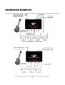
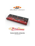
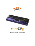
Features, Benefits, and Operation
© 2014 Decibel Eleven
Contents
Introduction ......................................................................... 2
Features .............................................................................. 2
Rear Panel........................................................................... 3
Connections ........................................................................ 3
Power......................................................................... 3
MIDI ........................................................................... 3
Pedal Loops .............................................................. 4
Example Connection Diagrams ............................. 5,6
Operation Basics ................................................................. 7
Operating Modes ....................................................... 7
Pedal Bypass Loops .................................................. 7
Input Buffer ............................................................... 8
Setup Mode ......................................................................... 9
Programming Presets ....................................................... 10
Specifications.................................................................... 11
Declaration of Conformity
Decibel Eleven declares that this product complies with the European Union Council Directives and Standards
requirements for the Low Voltage Directive (2006/95/EC) and the EMC Directive (2004/108/EC).
© 2014 Decibel Eleven
1
INTRODUCTION
The Decibel Eleven Loop Expander is a programmable audio switcher that adds truebypass effects loop switching to any MIDI controlled setup. The Loop Expander
includes four relay true-bypass audio loops, with the option to use the fourth loop as
a control switch. Use it to add loop switching to an existing system with a simple
MIDI controller, or use it to expand the number of true bypass loops in a Pedal
Palette or Switch Dr. setup. For larger setups, connect multiple Loop Expanders in
series.
Features:
• 4 relay true bypass audio loops
• 4th loop can be used for amp channel switching
• Switchable discrete, Class A input buffer
• Small form factor for mounting underneath pedals or on a rack shelf
• Multiple Loop Expanders can be connected in series
• Works with MIDI Program Changes or MIDI Control Changes
Website
Go to decibel11.com for videos, manuals, accessories, and more.
Contact us directly at [email protected].
2
REAR PANEL
To Amp
Power
To Pedal Input
Loop Status
From MIDI Controller
From Pedal Output
To Additional MIDI devices (if needed)
CONNECTIONS
Refer to the REAR PANEL diagram and CONNECTION EXAMPLES.
EXAMPLES
Power
The Loop Expander can be powered from any regulated 9VDC or 12VDC power
supply capable of providing a minimum of 150mA. It is highly recommended that a
well regulated and isolated 12V, 150mA (minimum) power supply is used for best
performance. The rear panel POWER jack is a standard 2.1mm DC power jack,
center negative connection.
The Loop Expander is capable of phantom powering a Decibel Eleven Switch Dr. with
a standard 5 wire MIDI cable, provided that the Loop Expander is supplied with at
least 300mA of available current. However, because the Switch Dr. and Loop
Expander each use DC power, there is a chance of creating ground loop when using
the phantom power. This results in a low frequency ground hum. If this occurs,
ground loops can be avoided by powering each on its own isolated power supply.
MIDI
Connect the MIDI IN of the Loop Expander to the MIDI OUT of your MIDI controller, or
to the MIDI OUT of the last device in the MIDI chain. Additional MIDI devices can be
connected from the MIDI THRU of the Switch Dr.
3
Pedal Loops
The Loop Expander can be connected either in front of the amplifier, or in the
amplifier’s effects loop.
When using the Loop Expander in front of the amplifier, connect the output of your
instrument or other source to the Loop Expander INPUT jack. Connect the OUTPUTOUTPUTN.O. jack to the amplifier input or next device input. Connect each pedal loop SEND
jack to a pedal input, and connect the pedal's output to the loop RETURN jack. One
or more pedals may be connected in series within a pedal loop. It may be useful in
some cases to combine similar types of pedals into a single loop, where only one of
the pedals will be used at a time. If more than one pedal is used in the loop, then
connect the loop SEND to the input of the first pedal. Connect the output of the last
pedal to the loop RETURN jack. Turn on all of the pedals that will be used so that
when the loop is activated, the pedal effect will be heard.
Pedal Loop 4 as Control Switch
It is possible to use the 4th bypass loop as a function control switch. This can be
used for amp channel control or amp tremolo switch, etc. When doing so, the 4th
loop is no longer available to be used as a pedal bypass loop. The final output from
the pedal effect chain is then taken from the jack labeled OUTPUT A. Leave the
LOOP 4 SEND and LOOP 4 RETURN jacks empty and use the OUTPUTOUTPUT-N.O. jack for
connecting to the normally-open switch control function. NOTE: this is a mono jack
for a single function switch.
Pedal Loop 4 as an A/B switch
Pedal Loop 4 (or Pedal Loop 3 if Pedal Loop4 is used as a switch) can be configured
as an A/B switch by connecting the loop's SEND jack to destination 'A' and
connecting the OUTPUTOUTPUT-N.O (or OUTPUT A if using Loop4 as SW3) jack to destination
'B'.
4
CONNECTION EXAMPLES
Fig. 1 – Basic setup with 4 pedal loops
Fig.2 - Basic setup with 3 pedal loops and 1 amp channel switch
5
CONNECTION EXAMPLES (CONT'D)
Fig.3 - Expanded setup using a Decibel Eleven Switch Doctor.
6
OPERATION BASICS
This section describes the basic controls and operation of the Loop Expander.
Operating Modes
The Loop Expander has two basic modes for controlling the loops. The method that you
use depends on which type of MIDI messages you send it.
If your MIDI controller is capable of sending MIDI Control ON/OFF type messages, then
you can use those messages to toggle the state of each individual bypass loop in the
Loop Expander. Using this type of control, you get instant access to the individual
loops, and you can create and store presets within your MIDI Controller.
If your MIDI Controller is not capable of sending MIDI Continuous Controller messages,
then you can use MIDI Program Change messages to load presets that you have
previously saved in the Loop Expander. In this mode, you first create and store your
presets in the Loop Expander. Then, when the Loop Expander receives a MIDI Program
Change on its channel it will load the corresponding preset number.
Refer to the SETUP MODE section on page 9 for details on setting the Operating Mode
and MIDI Channel.
Pedal Bypass Loops
The pedal bypass loops are typically used for inserting or bypassing pedal effects. This
acts to turn each pedal on or off. By having the pedals in the bypass loops, presets can
be created which can turn on and off multiple pedals with a single button press.
The bypass loops use mechanical relays to provide the cleanest and most direct
method of effect bypassing. The bypass loops are wired in series. If there is nothing
connected to a loop and it is switched on, the signal path will be broken.
A loop can be used for silent (muted) tuning by connecting only the SEND of a loop
to the tuner input, and leaving the loop RETURN jack empty.
The 4th pedal bypass loop can also be configured as a 3rd control function switch which
can be used for additional amp control, tremolo, reverb, etc. (for details see
CONNECTIONS – Pedal Loops on page 3).
7
True Bypass
Passive guitar pickups are low level, high impedance sources. They are easily loaded
down by all the various cable and connections required when using multiple effect
pedals, resulting in a loss of high frequency response.
Many effect pedals on the market use circuitry that is active even when the effect is
turned off. This “bypass” circuitry typically has high harmonic distortion and minimal
headroom, both of which can greatly affect the tone and dynamics of your playing.
Some pedals use a bypass design that loads the guitar signal down even when the
pedal is switched off. The cumulative effect of these issues can result in a loss of tone,
dynamics, and high frequency response - even when all your pedals are OFF.
The Loop Expander is a true bypass switcher, which means that, when all of the pedal
loops are switched off, your guitar signal goes directly from the input jack to the output
jack, bypassing all of the cables, connectors and pedals in the effect chain.* In order
to achieve a “straight wire” type of true bypass, the loop Expander utilizes relays. This
provides the most transparent bypass possible. However, because relays are
mechanical switches, it is understood that they inherently cause some noise when
switching.
* when the Input Buffer is switched OUT.
Input Buffer
The Loop Expander features a high quality, discrete, Class A input buffer circuit which
can help to prevent high frequency losses due to cables and connections. In many
cases the buffer will improve the overall clarity of tone. However, sometimes a direct
connection between the guitar and the amplifier is desired. And, some pedal inputs
(fuzz pedals, etc.) are designed such that their tone relies on a direct connection with
the guitar's pickups. For these reasons, the buffer circuit can be switched in or out
using the BUFFER switch on the front panel. Experiment with having the buffer in or out
and use which sounds best for your setup.
8
SETUP MODE
The Loop Expander default setup is set to MIDI Channel 1 and Program Change Mode.
To change these settings, use the setup mode.
Entering Setup Mode
To enter Setup Mode, disconnect power to the Loop Expander. Then, while pressing
and holding the EDIT button, reconnect the power. You will see the LEDS alternating
between LED1 and LED2. These represent the two setup functions, MIDI Channel and
operating Mode.
MIDI Channel
To set the MIDI Channel for the Loop Expander, follow the instructions above for
entering Setup Mode, then release the EDIT button while LED1 is on. The current MIDI
Channel is displayed as shown below. To change the current MIDI Channel, press and
hold the EDIT button to until the desired MIDI channel is displayed.
LED DISPLAY
MIDI CH.
LED DISPLAY
MIDI CH.
Operating Mode
To set the operating mode for controlling loops, follow the instructions above for
entering Setup Mode, then release the EDIT button while LED2 is on. The current
operating mode setting will be displayed as shown below. To change the operating
9
mode, press and hold the EDIT button until the desired operating mode is displayed.
LED DISPLAY
MIDI OPERATING MODE
Exiting SETUP MODE
At any time, to exit Setup Mode and save any changes, simply disconnect power to the
Loop Expander.
PROGRAMMING PRESETS
The Loop Expander can save up to 128 presets corresponding to MIDI Program Change
numbers 0-127 (sometimes numbered 1-128, depending on the controller). These
presets are used in the Program Change mode only (see Operating Modes and Setup
Mode above).
To program a preset, first select the preset you wish to program with your MIDI
Controller. Once the Loop Expander receives the MIDI Program Change on its MIDI
Channel, it will load whatever is currently saved for that preset. To change the loop
settings, press and hold the EDIT button until the desired loop combination is
displayed. Then release the EDIT button while the display is showing the desired loops,
and the new preset is saved automatically.
NOTE: When editing a preset, the loops do not actually change states until the EDIT
button is released.
10
SPECIFICATIONS
Bypass method:
Relay True Bypass or Analog Buffered.
Buffer Specifications:
Type:
Discrete Class A, JFET input
Input Impedance:
1 MΩ
Max. Input Level:
+12 dBu
Frequency Response: +0.0/-0.2 dB, 10 Hz - 100 kHz
S/N Ratio:
>96 dB, 0 dBV ref. (no weighting)
THD+N:
<0.005%, -10 dBV, 20 Hz - 30 kHz
Output impedance:
400 Ω
Max. Output Level:
+12 dBu into 10 kΩ
Power:
9-12 VDC, 150 mA, center negative
(12V DC isolated & regulated recommended)
Dimensions:
6.34" x 4.73" x 1.20" (W x D x H)
Weight:
1.3 lbs.
11