1
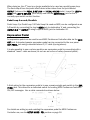
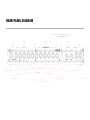
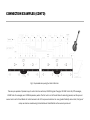
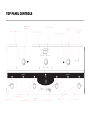
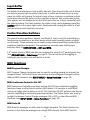
Features, Benefits, and Operation
© 2013 Decibel Eleven
VERSION 1.3 ADDENDUM
IMPORTANT: The following pages document the operational changes made in
Switch Dr. version 1.3. Keep it with your user manual for future reference.
Switching between Preset Mode and Direct Mode:
The method for switching back and forth between Direct Mode and Preset Mode has
been changed to make it more fluid to go between the two modes.
To toggle between Preset Mode and Direct Mode,
press and release only the EDIT switch.
Direct Mode is no longer available from Split Mode.
Changes to Direct Mode:
This section replaces parts of DIRECT MODE on page 11 of the user manual:
The instant access switches used in Direct Mode have been revised. The ▲ and ▼
switches no longer control SW1 and SW2. Instead, the instant access switches are
split into several pages based on their function (bypass loops are on one page, control
function switches are on another page, etc.). The ▲ and ▼ switches are used to scroll
through the available pages.
There are up to four available instant access pages as follows:
LPS is a dedicated page for the bypass loops. Pedal bypass loops are toggled on and
off using the bottom row switches 4, 3, 2, 1. The red LEDs above each switch indicate
the state of the loops.
FnS is used for the control function switches (SW1 and SW2). The bottom row
switches 1&2 control SW1, and switches 3&4 control SW2 (Both switches nearest to
each indicator LEDs are able to be used to control the switches – use either).The
yellow status LEDs are located above the footswitches.
CC.A (only available if activated in SETUP MODE) is used for instant access control of
the CC.A MIDI Control On/OFF switches. The red LEDs above each switch indicate the
state of the controllers.
CC.B (only available if activated in SETUP MODE) is used for instant access control of
the CC.B MIDI Control On/OFF switches. The red LEDs above each switch indicate the
state of the controllers.
As you toggle back and forth between Preset Mode and Direct mode, the instant
access page will stay where you leave it. This is useful if there is one page that you
want to access most. For example, if you are using Direct Mode to mainly control your
pedal loops, then you can simple leave the page set to LPS. If you mostly use Direct
Mode for switching amp channels, then you can select the FnS page and it will
always be what you see first when entering Direct Mode.
MIDI CC Switch Type:
Refer to page 16 of the user manual for details on programming MIDI CC switches.
The MIDI Continuous Controller ON/OFF switches can now be configured to send ON
messages ONLY. When this mode is selected, an activated MIDI CC switch will only
send a value of 127. When the switch is set to OFF in a preset, no MIDI data is sent.
This can be useful for certain types of effect devices and when controlling the
functions of a delay/looper pedal.
Each CC switch group, CC.A and CC.B , can be independently set to either “normal”
type or “only-send-on” type. Refer to page 16 of the user manual for details on
programming the MIDI CC switches. In SETUP MODE->CC.A, the controller numbers
are assigned sequentially using the ► switch. Following the last switch (#4)
assignment, pressing the ► switch again displays the setting for the CC switch type:
nOr = normal (on/off), and oSo = only-send-on. Use the ◄ switch to return to the
controller number assignments. The same setting is available for SETUP MODE->CC.B
When used in a preset, this type of CC switch offers a convenient way to not send CC
data by leaving the switch OFF. In this way, a preset can be programmed to only send
a single MIDI CC message.
In Direct Mode or Split Mode, the instant access switches will send the MIDI CC ON
message every time they are pressed. The LED will blink briefly to indicate the
message was sent, but the LED status will not change. This is normal operation for
these switches when used in instant access mode. Typical instant access use for
these switches are for real time event functions such as looper control or tap tempo.
Therefore, the LED and switch status in this mode is not intended to toggle.
Features, Benefits, and Operation
Contents
Introduction............................................................................2
Features.................................................................................2
Connections...........................................................................3
Power...........................................................................3
MIDI..............................................................................3
SW1 and SW2..............................................................3
Pedal Loops.................................................................3
Expression Pedal.........................................................4
Rear Panel Diagram....................................................5
Example Connection Diagrams..................................6
Top Panel Controls................................................................8
Operation Basics...................................................................9
Operating Modes.........................................................9
Preset Mode................................................................9
Direct Mode...............................................................11
Pedal Bypass Loops..................................................12
Input Buffer...............................................................13
Control Function Switches........................................13
MIDI Functions..........................................................13
MIDI Expression Pedal..............................................14
Setup Mode.........................................................................15
Programming Presets.........................................................20
Factory Reset.......................................................................21
Specifications......................................................................22
Declaration of Conformity
Decibel Eleven declares that this product complies with the European Union Council Directives and Standards
requirements for the Low Voltage Directive (2006/95/EC) and the EMC Directive (2004/108/EC).
© 2013 Decibel Eleven
1
INTRODUCTION
The Switch Doctor is a fully programmable MIDI control pedal which includes four relay
true-bypass audio loops, and two switch control functions. It is designed to be a central
control unit for switching amplifier and effect configurations. It features the ability to
store and recall presets, enabling the user to select amp channel, switch multiple
pedals on and off, and send multiple MIDI commands on multiple MIDI channels - all
simultaneously with a single button press.
In addition, multiple Switch Doctors and or Pedal Palettes can be linked together in
series to create an expanded setup with more pedal loops, and switches.
Features
•
128 presets capable of sending:
•
Up to 3 MlDl program changes on 3 MlDl channels
•
Up to 8 MlDl continuous controller On/Off messages on 2 MlDl channels
•
Up to 4 MlDl Note-On messages for triggering samplers
•
Expression Pedal MlDl Continuous Controller Data
•
Up to 4 true bypass pedal effects loops.
•
Up to 3 switch control functions for amp channel switching, etc.
•
Optional discrete Class A input buffer
•
Direct mode for instant access to individual switches
•
External expression pedal input.
•
Optional "global" default preset.
•
Presets can be recalled remotely by MlDl for syncing multiple switchers/controllers.
Website
Go to decibel11.com for videos, manuals, accessories, and more.
Contact us directly at [email protected].
2
CONNECTIONS
Refer to the REAR PANEL DIAGRAM and CONNECTION EXAMPLES on the next pages.
Power
The Switch Doctor can be powered from any regulated 9VDC or 12VDC power supply
capable of providing a minimum of 200mA. It is highly recommended that a well
regulated and isolated 12V, 200mA (minimum) power supply is used for best
performance. The rear panel POWER jack is a standard 2.1mm DC power jack, center
negative connection.
MIDI
Connect the MIDI OUT of the Switch Doctor to the MIDI IN of the first MIDI device using
a 5-pin MIDI cable. Additional MIDI devices can be connected from the MIDI THRU or
MIDI OUT of the first device.
SW1 and SW2
The control function switches, Switch1 and Switch 2 are configured as normally-open
latching switches. Prior to connecting, refer to the user manual for the amplifier or
effect device and verify that the device's footswitch jack is designed to accommodate a
single (mono) normally-open latching type switch. Connect the footswitch control jack
of the amplifier or effect device to the desired SW1 or SW2 jack on the Switch Doctor
using a standard 1/4” mono cable.
Pedal Loops
Connect the instrument output to the Switch Doctor INPUT jack. Connect the OUTPUTN.O. jack to the amplifier or next device input. Connect each pedal loop SEND jack to a
pedal input, and connect the pedal's output to the loop RETURN jack. One or more
pedals may be connected in series within a pedal loop. It may be useful in some cases
to combine similar types of pedals into a single loop, where only one of the pedals will
be used at a time. If more than one pedal is used in the loop, then connect the loop
SEND to the input of the first pedal. Connect the output of the last pedal to the loop
RETURN jack. Turn on the pedal(s) to be used so that when the loop is activated, the
pedal effect will be heard.
Pedal Loop 4 as SW3
It is possible to use the 4th bypass loop as an additional 3rd function control switch
(SW3). For example, as an additional amp channel control or amp tremolo switch, etc.
3
When doing so, the 4th loop is no longer available to be used as a pedal bypass loop.
The final output from the pedal effect chain is then taken from the jack labeled
OUTPUT (between the PEDAL 3 RETURN and PEDAL 4 SEND jacks). Leave the LOOP 4
SEND and LOOP 4 RETURN jacks empty and use the OUTPUT-N.O. jack for the 3rd
normally-open switch control function.
Pedal Loop 4 as an A/B switch
Pedal Loop 4 (or Pedal Loop 3 if Pedal Loop4 is used as SW3) can be configured as an
A/B switch by connecting the loop's SEND jack to destination 'A' and connecting the
OUTPUT-N.O (or OUTPUT if using Loop4 as SW3) jack to destination 'B'.
Expression Pedal
An expression pedal can be used to send MIDI Continuous Controller data via the MIDI
OUT jack. A standard passive expression pedal can be connected to the rear panel
EXP. PEDAL jack using a standard stereo 1/4” cable (tip-ring-sleeve).
It is also possible to use a volume pedal as an expression pedal by connecting with a
standard “insert” cable as shown (do not use an active or battery powered pedal).
A third option for the expression pedal is to use a passive single-pole switch in the EXP.
PEDAL jack. This allows for a dedicated switch for sending MIDI Continuous Controller
ON/OFF messages. Use a cable connected as shown below:
For details on setting up and enabling the expression pedal for MIDI Continuous
Controller use, see the SETUP MODE– PDL section on page 16.
4
REAR PANEL DIAGRAM
CONNECTION EXAMPLES
Fig. 1 – Basic setup with amp channel switching and MIDI expression pedal
Fig.2 - Expanded setup with optional multiple pedals per loop and MIDI amp control
6
CONNECTION EXAMPLES (CONT'D)
Fig.3 - Expanded setup using two Switch Doctors.
This setup is capable of 8 pedal loops, 4 control function switches, 6 MIDI Program Changes, 16 MIDI Control On/Off messages,
8 MIDI Note-On messages, and 2 MIDI Expression pedals. The first unit is set to Preset Mode for selecting presets, and the synced
second unit is set to Direct Mode for instant access to all of it's loops and switches. For even greater flexibility and control, this type of
setup can also be created using a Decibel Eleven Pedal Palette as the second synced unit.
TOP PANEL CONTROLS
OPERATION BASICS
This section describes the basic controls and operation of the Switch Doctor. Refer to
the TOP PANEL CONTROLS diagram on the previous page.
Operating Modes
The Switch Doctor has two operating modes – Preset Mode and Direct Mode. Preset
Mode is used to create, recall, and edit presets. Direct Mode is used for instant access
to the individual pedal loops, control switches, and MIDI Continuous Controller
switches (if enabled in Setup). The Switch Doctor ships from the factory in Preset
Mode, but will power up in whichever mode was last used.
To toggle between Preset Mode and Direct Mode,
press the 1 and ▲ switches simultaneously.
Preset Mode
When the Switch Doctor is powered up for the first time, it is in Preset Mode. The
numeric display will read 01 and the blue preset LEDs will cycle from left to right. The
Switch Doctor has 128 user presets which are configured as 32 banks of 4 presets. In
this mode, the numeric display indicates the selected bank number (01-32) and the
switches along the bottom row select the preset within the bank (A,B,C,D). Use the ▲
and ▼ switches in the top row to select the next desired bank. When scrolling through
the bank numbers, a bank is not active until a preset is selected within the bank. When
there is no preset selected in the bank, the blue preset LEDs will sequence from left to
right. Once a preset is selected, it's blue preset LED will light solid, and the
programmed preset will be activated.
In it's factory default state, the Switch Doctor can be immediately used as a simple
MIDI program controller in Preset Mode. The Switch Doctor defaults to sending a
single MIDI Program Change message for each of it's 128 presets on MIDI
Channel1. The first preset (Preset A in Bank 1) will send MIDI Program Change 0.
The next preset will send MIDI Program Change 1, etc. So, the presets on the Switch
Doctor will automatically call up the corresponding presets on your MIDI device.
Global Preset
An additional “global” preset is optionally available as a 5th preset in any active bank.
The global preset is useful for accessing a “default sound” that is often used, such as a
basic clean sound or a lead sound. Since it is available from any active bank, it is
always quickly accessible and does not need to be programmed multiple times for
9
multiple banks. Since the global preset is an optional feature, it must first be enabled
in Setup Mode prior to use (see SETUP MODE – Global Preset on page 18). Once
enabled in Setup Mode, the global preset can be activated by pressing the footswitch
of the currently selected preset again. If there is no preset selected, then a preset
footswitch can be pressed twice. The previously selected preset LED will turn off and
the numeric display will indicate that the global preset is activated by showing a single
dash in it's leftmost position. When the global preset is activated, you may then select
any other preset in the same way as in typical Preset Mode operation.
Preset Data
A Switch Doctor preset is capable of making multiple changes to your setup with a
single button press. This can include all of the functions listed in the introduction
section of this manual. However, it is also possible to create presets which have a
specific function, and are not intended to make complete system wide changes. For
example, a preset can be programmed to change only the function switches or amp
channel (without changing anything else). Or, a preset can be configured to only send a
MIDI Note-On message without changing any of the the MIDI Program Changes, loops,
or switch states (see PROGRAMMING PRESETS on page 18 for more information).
For details on enabling MIDI and user options, see the SETUP MODE (page 15).
For preset programming and editing, see PROGRAMMING PRESETS (page 20).
Split Mode
Split Mode is an alternative Preset Mode which allows the top row switches to select
presets and the bottom row switches to become instant access switches. To access
this mode, it must be enabled in SETUP mode (see SETUP MODE – Split Mode on page
18). Within the setup, the bottom row switches can be assigned to control either the
bypass loops or MIDI Continuous Controller on/off messages. The top row switches
utilize the ▲ and ▼ switches to scroll through the presets numbers 001- 128.
Split mode is indicated by the display showing the three-digit preset number followed
by a decimal point. The blue preset LEDs will be off.
There are two options in setup for selecting presets in Split Mode– instant or deferred
(see SETUP MODE – Split Mode on page 18). With instant selection, the preset is
loaded each time the ▲ or ▼ switches are pressed. This is convenient if the presets
are organized in order of planned use (per song, etc). With deferred selection, the ▲
and ▼ switches are used to scroll through the preset numbers without actually
10
selecting the preset (preset numbers will be displayed as flashing until selected). When
the desired preset number is displayed, it can be selected and loaded by pressing the
middle EDIT switch.
In Split Mode, the middle LED strip is used exclusively to indicate the current status of
the instant access switches on the bottom row. Only the red LEDs are used. The yellow
control switch LEDs are not used in Split Mode (the control switches are still updated
with the presets, though).
Direct Mode
Direct Mode provides direct instant access to the pedal loop, switch states, and MIDI
continuous controller switches (if enabled in setup). To enter Direct Mode from Preset
Mode, press the 1 and ▲ switches simultaneously. This button combination is used to
toggle back and forth between Preset Mode and Direct Mode, providing the flexibility to
quickly make spontaneous changes.
In Direct Mode, the numeric display will show --- , indicating instant access to pedal
bypass loops and control function switches. Pedal bypass loops are toggled on and off
using the bottom row switches 4, 3, 2, 1. The red LEDs above each switch indicate the
state of the loops. When the loop is ON, the pedal(s) in the loop are inserted into the
signal path. When the loop is OFF, the pedal(s) in the loop are bypassed.
With the display still showing ---, the control function switches Switch1 and Switch2
can be toggled using the ▲ and ▼ footswitches, respectively. The Switch's label and
yellow status LED are located just below each footswitch. The control function switches
can be used in place of an amplifier's dedicated footswitch for changing amp channels
(see CONNECTIONS – SW1 and SW2 on page 3).
If MIDI Continuous Controllers are enabled in Setup Mode (see SETUP MODE on page
15 for details on enabling MIDI functions), then additional page(s) of direct access
switches are available. By pressing the EDIT switch while in Direct Mode, you will toggle
through the enabled CC pages. There is one Direct Mode page for each of the two MIDI
CC channels. The display will show CCA, CCB or --- to indicate the current page.
Saving instant access switches to a preset
When in Direct Mode, all of the switch and loop states can easily be saved as a preset
by pressing and holding the EDIT switch until the blue EDIT LED lights. The display will
scroll SAVE followed by the current bank number. The blue preset LEDs will sequence
from left to right. Select the preset number to save to by first selecting the bank
number using the ▲ and ▼ switches. Then, use the bottom row switches to select the
desired preset within the bank (A,B,C,D). Once the desired bank and preset are
selected, press the EDIT switch again and the display will scroll SAVE followed by
alternating n and Y. Press the + (y)switch to save, or press the – (n) switch to
11
return to Direct Mode without saving.
Note: if a preset is selected, and it is desired that a different selection be made, press
the selected preset switch again to de-select it.
Pedal Bypass Loops
The pedal bypass loops are typically used for inserting or bypassing pedal effects. This
acts to turn each pedal on or off. By having the pedals in the bypass loops, presets can
be created which can turn on and off multiple pedals with a single button press.
The bypass loops use mechanical relays to provide the cleanest and most direct
method of effect bypassing. The bypass loops are wired in series. If there is nothing
connected to a loop and it is switched on, the signal path will be broken.
A loop can be used for silent (muted) tuning by connecting only the SEND of a loop
to the tuner input, and leaving the loop RETURN jack empty.
The 4th pedal bypass loop can also be configured as a 3rd control function switch which
can be used for additional amp control, tremolo, reverb, etc. (for details see
CONNECTIONS – Pedal Loops on page 3).
True Bypass
Passive guitar pickups are low level, high impedance sources. They are easily loaded
down by all the various cable and connections required when using multiple effect
pedals, resulting in a loss of high frequency response.
Many effect pedals on the market use circuitry that is active even when the effect is
turned off. This “bypass” circuitry typically has high harmonic distortion and minimal
headroom, both of which can greatly affect the tone and dynamics of your playing.
Some pedals use a bypass design that loads the guitar signal down even when the
pedal is switched off. The cumulative effect of these issues can result in a loss of tone,
dynamics, and high frequency response - even when all your pedals are OFF.
The Switch Doctor is a true bypass switcher, which means that, when all of the pedal
loops are switched off, your guitar signal goes directly from the input jack to the output
jack, bypassing all of the cables, connectors and pedals in the effect chain.* In order
to achieve a “straight wire” type of true bypass, the Switch Doctor utilizes relays. This
provides the most transparent bypass possible. However, because relays are
mechanical switches, it is understood that they inherently cause some noise when
switching.
* when the Input Buffer is switched OUT.
12
Input Buffer
The Switch Doctor features a high quality, discrete, Class A input buffer circuit which
can help to prevent high frequency losses due to cables and connections. In many
cases the buffer will improve the overall clarity of tone. However, sometimes a direct
connection between the guitar and the amplifier is desired. And, some pedal inputs
(fuzz pedals, etc) are designed such that their tone relies on a direct connection with
the guitar's pickups. For these reasons, the buffer circuit can be bypassed using the
BUFFER switch in the upper right corner. Experiment with having the buffer in or out
and use which sounds best for your setup.
Control Function Switches
The control function switches, Switch1 and Switch2, can be used for controlling any
functions on an amplifier or an effect device which would normally require a typical
on/off switch. These switches can be used for amp channel switching, replacing the
amplifier's dedicated footswitch. The switches are normally-open latching type
switches. Refer to CONNECTIONS – SW1 and SW2.
A 3rd switch function (SW3) can also be configured by using the 4 th pedal bypass loop.
(see CONNECTIONS – Pedal Loops on page 3). This can be useful for toggling an
additional amp function such as tremolo or boost.
MIDI Functions
MIDI Program Changes
MIDI Program Change commands can be used for recalling presets on devices that
recognize them. The Switch Doctor can send up to three Program Changes on three
different MIDI channels. (see SETUP MODE – Setup Functions on page 15)
MIDI Continuous Controller ON/OFF
MIDI Continuous Controllers are often used as ON/OFF type switches for toggling
functions, loops, or effect blocks within a MIDI device. For example, a multi-effect
device can toggle just the delay, on or off. The Controller ON/OFF switches can also be
used for controlling an external bypass loop switcher. The Switch Doctor can send up
to eight Continuous Control Change messages (ON or OFF) on two different MIDI
channels. (see SETUP MODE – Setup Functions on page 16).
MIDI Note ON
MIDI Note-On messages are often used to trigger samplers. The Switch Doctor can
send up to four Note-On messages on a single MIDI channel. Each MIDI Note-On
13
message is quickly followed by a Note-Off message, as if a key was quickly pressed
and released. This helps to prevent stuck notes. Most samplers can be set to trigger
only with Note-On messages, ignoring the Note-Off (see SETUP MODE – NTE on page
16).
MIDI Expression Pedal
Using an expression pedal with the Switch Doctor allows MIDI Continuous Controller
data to be sent when the pedal is moved.
The Continuous Controller Number and the MIDI Channel for the expression pedal can
be assigned per preset. This allows the pedal to be assigned to different MIDI devices
for different presets (see PROGRAMMING PRESETS – PDL on page 21).
There is also a global MIDI channel for the expression pedal which can be used to set
the channel for all presets. This is useful for using the pedal to control a single MIDI
device (single MIDI Channel). See SETUP MODE – PDL on page 17 for details on
setting up the pedal.
By default, when a preset is recalled on the Switch Doctor, the current expression
pedal position is not transmitted. The pedal position data is transmitted once the pedal
is moved. However, it is possible to transmit the current pedal position when a preset
is recalled by enabling the option in Setup Mode. See SETUP MODE – PDL on page 17
for details on setting up the pedal.
14
SETUP MODE
The Switch Doctor Setup Mode is used for enabling or disabling various MIDI and
global features, setting MIDI Channels and selecting MIDI Continuous Controller and
note numbers.
Entering Setup Mode
To enter the Setup Mode, press the ▲ and ▼ footswitches simultaneously. The
numeric display will scroll SETUp followed by the abbreviated name of the first
function to be setup.
Setup Functions
All of the available setup functions are arranged in a list. Use the ▲ switch to advance
to the next function, and ▼ switch to go to the previous function. When a function
name is displayed, it's details and options can be viewed by using the arrow right ( ► )
to access the function's individual edit page(s). Return to the main setup function list
by using either the left arrow ( ◄ ) or by using the ▲ and ▼ switches to advance to
another function.
PC.1 (MIDI Program Change 1)
Program Change 1 sends a unique fixed MIDI Program Change number for each of the
Switch Doctor's 128 presets. For example, the first preset (Preset A, Bank 1) sends a
MIDI program change 0, the next preset sends MIDI Program Change 1, etc. This MIDI
Program Change number cannot be edited within a preset. PC1 provides simple and
effective MIDI control without the need to program presets, and it provides a quick and
easy way to synchronize multiple units.
Press the ► switch to view the current MIDI Channel for Program Change 1. Use the
+ / - switches to edit the current channel. Set to OFF to disable this program change.
PC.2 (MIDI Program Change 2)
Program Change 2 is fully programmable per preset. MIDI messages use numbers 0 to
127 for program changes. Since most devices label their presets from 1 to 128, the
Switch Doctor displays them as 1 to 128. The actual MIDI message sends as 0 to 127.
Press the ► switch to view the current MIDI Channel for Program Change 2. Use the
+ / - switches to edit the current channel. Set to OFF to disable this program change.
15
PC.3 (MIDI Program Change 3)
Program Change 3 is fully programmable per preset. MIDI messages use numbers 0 to
127 for program changes. Since most devices label their presets from 1 to 128, the
Switch Doctor displays them as 1 to 128. The actual MIDI message sends as 0 to 127.
Press the ► switch to view the current MIDI Channel for Program Change 3. Use the
+ / - switches to edit the current channel. Set to OFF to disable this program change.
CC.A (MIDI Continuous Control switches A)
Sets the MIDI Channel and the MIDI Continuous Controller (CC) numbers for each of
the first four CC on/off messages.
Press the ► switch to view the current MIDI Channel. Use the + / - switches to edit the
current channel. Set to OFF to disable these continuous controllers.
Press the ► switch again to display the first of four Continuous Controller numbers for
this MIDI Channel. The red LED above each switch number, 1 - 4, indicates which of
the four Continuous Control switches is being edited. Use ► to advance to the next
switch and ◄ to return to the previous switch. Use the +/- switches to set the MIDI
Continuous Controller number for each switch.
CC.B (MIDI Continuous Control switches B)
Sets the MIDI channel and the MIDI Continuous Controller (CC) numbers for each of
the second four CC on/off messages.
Press the ► switch to view the current MIDI Channel. Use the + / - switches to edit the
current channel. Set to OFF to disable these continuous controllers.
Press the ► switch again to display the first of four Continuous Controller numbers for
this MIDI Channel. The red LED above each switch number, 1 - 4, indicates which of
the four Continuous Control switches is being edited. Use ► to advance to the next
switch and ◄ to return to the previous switch. Use the +/- switches to set the MIDI
Continuous Controller number for each switch.
nte (MIDI Notes)
Sets the MIDI Channel and MIDI Note numbers for the four MIDI Note-On messages.
Press the ► switch to view the current MIDI Channel. Use the + / - switches to edit the
current channel. Set to OFF to disable MIDI note messages.
Press the ► switch again to display the first of four note numbers for this MIDI
Channel. The red LED above each switch number, 1 - 4 indicates which of the four
Note switches is being edited. Use ► to advance to the next switch and ◄ to return to
the previous switch. Use the +/- switches to set the MIDI Note number for each switch.
16
pdl (Expression Pedal Continuous Controller)
Expression Pedal sets the global MIDI Channel for expression pedal data, and sets the
functions related to the handling of expression pedal data.
The MIDI Channel set here is the default global channel which can be used for
expression pedal data. Please note that when programming presets, the expression
pedal can be assigned to any MIDI Channel, allowing a single pedal to be used with
several different MIDI devices. However, if only one MIDI device is to receive pedal
data, it is recommended to set it's MIDI Channel here. All presets will default to this
global channel for expression pedal data.
Press the ► switch to view the current MIDI Channel. Use the + / - switches to edit the
current channel. Set to OFF to disable the expression pedal.
Press ► again to display the “Transmit Pedal with Preset” setting ( tr). This setting
determines whether the current pedal position will be transmitted when a preset is
activated. Use the + / - switches to set the value. When set to no (n), the pedal value
will not be transmitted when a preset is recalled, but will be transmitted once the pedal
is moved (value change). Set the transmit value to yes (y) to have the pedal's position
value transmitted when a preset is recalled, and also transmitted when the pedal is
moved.
Press the ► switch again to display the “Pedal Type” ( ty ). The expression pedal input
can be treated as either a continuous pedal or as an on/off switch. Use the + / switches to set the type. The default type is “pedal” (p). If a switch is used in the
expression pedal jack, then the type should be set to “switch” (s).
rCH (MIDI Program Change Receive)
This is the setting for syncing to incoming MIDI Program Changes. When a MIDI
Program Change message is received on this channel, the Switch Doctor will respond
by recalling one of the 128 presets.
Press the ► switch to view the current MIDI Channel. Use the + / - switches to edit the
current channel. Set to OFF to disable expression pedal data.
REC (MIDI Receive Echo)
This sets the MIDI output port echo behavior. Setting this value to NO will block
incoming MIDI messages from being re-transmitted to the MIDI output.
Press ► to display the current setting. Use the + / - switches to select yes or nO.
17
G.Pr (Global Preset)
The Global Preset can be used as a “default sound” preset. Preset number 128 (bank
32, preset D) is used as the Global Preset. But, if enabled here, this preset can be
activated from any active bank of the Switch Doctor. See the OPERATION BASICSPreset Mode on page 9 for more details.
Press ► to display the current setting. Use the + / - switches to select yes or nO.
SPL (Split Preset Mode)
The Split Preset Mode is an alternate Preset Mode that uses the top row switches for
selecting presets and the bottom row switches for instant access control. See the
OPERATION BASICS - Split Mode on page 10 for more details.
Press ► to display the current enabled status. Use the + / - switches to select yes or
nO. Press ► again to display the type of instant access switches selected. The options
are LPS for loops, CCA or CCB for MIDI Continuous Controllers. [NOTE: the MIDI
Continuous Controllers, CCA or CCb, must be defined and enabled before they can be
selected here (see page 16)] Press ► again to display the preset selection type –
instant (INS) or deferred (dEF).
dSP (Display)
The Display setting provides an alternate method of displaying the bank/preset when
in Preset Mode.
Press ► to display the current setting. Select BANK ( ban) to show the bank number
in the numeric display in Preset Mode (default). Select PRESET (pre) to show the
actual preset numbers 001 – 128 in the numeric display. This can be useful when
using the Switch Doctor as a simple MIDI controller since the preset number displayed
is the same as the MIDI Program Change number transmitted* (when PC1 is enabled).
* MIDI Program Changes 1 to 128 are transmitted as 0 to 127
ddr (Data Dump Receive)
For receiving a MIDI data dump of all of the memory (including presets and global
settings).
Press the + switch to initialize the receiver. The display will flash In while it waits for
incoming MIDI system exclusive data appropriate for the Switch Doctor. To cancel the
input request, press the ▲ or ▼ switch.
18
ddt (Data Dump Transmit)
For transmitting a MIDI data dump of all of the memory (including presets and global
settings).
Press the + switch to initiate the sending of MIDI sysex data. The display will read Out
while the red LEDs will cycle from right to left to indicate the data is being transmitted.
Exiting SETUP MODE
At any time, to exit Setup Mode and save any changes, press the EDIT switch. All LEDs
will flash once, and operation will return to the previously used operating mode.
19
PROGRAMMING PRESETS
While in Preset Mode, first select the preset to be programmed. Then, press and hold
the EDIT switch until the blue EDIT LED lights. The display will show the first enabled
function to be programmed. Use the ▲ and ▼ footswitches to step through the
enabled functions to be programmed. Refer to the specific instructions for each
function type below:
Please note that only MIDI functions that are enabled in Setup Mode will be visible
(the bypass loops and the control function switches are always shown). The following
instructions describe the editing procedure for all of the possible MIDI functions,
whether they are enabled or not:
PC.2 (MIDI Program Change 2)
Press the ► switch to edit the MIDI Program Change number to send on the MIDI
Channel assigned to Program Change 2 (PC2) in Setup Mode . To disable sending PC2
for this preset, set to OFF.
PC.3 (MIDI Program Change 3)
Press the ► switch to edit the MIDI Program Change number to send on the MIDI
Channel assigned to Program Change 3 (PC3) in Setup Mode. To disable sending PC3
for this preset, set to OFF.
CC.A (MIDI Control Changes A)
Use the bottom row switches 1,2,3,4 to set the ON or OFF states for each of the four
controller switches assigned to Continuous Controller Switches A (CCA) in Setup Mode.
To disable sending CCA data for this preset, press switches 1 and 4 simultaneously.
The numeric display will begin to flash CC.A indicating that no CCA controller data will
be sent with this preset.
CC.B (MIDI Control Changes B)
Use the bottom row switches 1,2,3,4 to set the ON or OFF states for each of the four
controller switches assigned to Continuous Controller Switches B (CCB) in Setup Mode.
To disable sending CCB data for this preset, press switches 1 and 4 simultaneously.
The numeric display will begin to flash CC.b indicating that no CCB controller data will
be sent with this preset.
Nte (MIDI Note-On)
Use the bottom row switches 1,2,3,4 to set which notes (assigned in Setup Mode) to
send a MIDI Note-On message for. If no switches are ON, then no MIDI Note data is
sent for this preset.
20
LPS (Bypass Loops)
Set the pedal bypass loop states using the bottom row switches. To ignore the pedal
bypass loops and create a preset that does not alter their states, press switches 1 and
4 simultaneously. The numeric display will begin to flash LPS to indicate that the loop
states will not be changed with this preset.
Fns (Function Switches)
Set the function switch states using the bottom row switches 1 and 2. To ignore the
function switches and create a preset that does not alter their states, press switches 1
and 4 simultaneously. The numeric display will begin to flash Fns to indicate that the
function switch states will not be changed with this preset.
Pdl (Expression Pedal)
Press the ► switch to display the expression pedal MIDI Channel for this preset. Use
the +/- switches to edit the channel. The available options are OFF, Gbl, and 01
thru16. When set to OFF, the expression pedal is not active and pedal data is not sent
for this preset. When set to GBL, the global pedal channel assigned in Setup Mode will
be used (see Setup Mode- Expression Pedal Continuous Controller on page 17).
Press ► again to set the expression pedal MIDI Continuous Controller number. Use the
+/- switches to set the value.
Saving and Exiting Preset Programming
To exit Preset Programming, press the EDIT switch at any time. If any changes were
made to the preset data (including changes made to instant access switches in Split
Preset Mode), the display will scroll saVE and will then alternate flashing between yes
( y) and no ( n). Select yes (+ switch) to save the changes. Press no (- switch) to exit
without saving.
FACTORY RESET
To restore the Switch Doctor to it's factory default settings, first disconnect power to
the unit. Next, hold down the – and + footswitches (2 & 3) simultaneously while
connecting power to the unit. The display will scroll factory reset erase
all, followed by: n y. Select YES by pressing the + footswitch. This will erase all
presets and will initialize setup functions to their factory defaults. To exit without
resetting the memory, simply press any switch other than the + footswitch, or
disconnect power to the unit.
21
SPECIFICATIONS
Bypass method:
Relay True Bypass or Analog Buffered.
Buffer Specifications:
Type:
Discrete Class A, JFET input
Input Impedance:
1 MΩ
Max. Input Level:
+12 dBu
Frequency Response: +0.0/-0.2 dB, 10 Hz - 100 kHz
S/N Ratio:
>96 dB, 0 dBV ref. (no weighting)
THD+N:
<0.004%, -10 dBV, 20 Hz - 30 kHz
Output impedance:
400 Ω
Max. Output Level:
+12 dBu into 10 kΩ
Power:
9-12 VDC, 200 mA, center negative
(12V DC isolated & regulated recommended)
Dimensions:
13.2” x 5” x 1.6” (W x D x H)
Weight:
3 lbs.
22