1
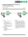
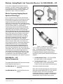
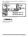
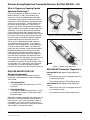
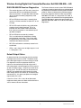
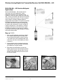
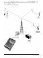
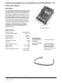
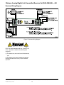
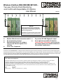
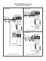
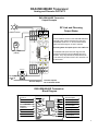
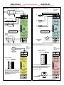
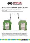
Wireless Interface Products
One-way Wireless System
Module
Grouping
DIN mount
Transmitter/Receiver
set
Conduit fit
transmitter/DIN
mount receiver
Conduit fit
transmitter/DIN
mount receiver
Product Description
Type Description/
Order Number
Datasheet/ CAD
Manual Drawing
One-way wireless system for
Datasheet
one 4-20mA and two discrete
24
signals. DIN rail mount
Manual
V dc
17.5mm wide integrated
RAD-ISM-900-SET-UD-ANT
radio with I/O.
2867102
One-way wireless system for
one 4-20mA and two discrete
signals. Weather proof
110(NEMA 4X) conduit mount
RAD-ISM-900-SET-AC-UD
240
transmitter with DIN rail
2867021
V ac
mount receiver. Accepts ac
(110-240 V ac) line voltage
inputs.
One-way wireless system for
one 4-20mA and two discrete
12- signals. Weather proof
RAD-ISM-900-SET-DC-UD
30 (NEMA 4X) conduit mount
2867034
V dc transmitter with DIN rail
mount receiver. Accepts ac
(12-30 V dc) voltage inputs.
Manual
Manual
DIN mount ReceiverSpare
Spare receiver to be used as
replacements or to duplicate
24
the receiving signals in oneV dc
way point to multipoint
applications
RAD-ISM-900-RX
2867047
Datasheet
Manual
Two-way Wireless System (with expandable I/O options)
Module
Grouping
Product Description
[No image]
ME BOS-KA (protective
plugs for female side bus)
ME B-SA/NS 35 (protective
cover for male side bus)
Integrated Radio
with I/O
Two-way radio transceiver
set with 0ne 4-20mA in/out
and two discrete signals
in/out. 22.5mm wide with
bus connection for power
and communication. Does
9- not include antennas.
30
V Two-way radio transceiver
dc set with 0ne 4-20mA in/out
and two discrete signals
in/out. Includes 1/4 wave
whip antenna with 6' cable.
22.5mm wide with bus
connection for power and
communication.
Type Description/
Order Number
Datasheet/ CAD
Manual Drawing
ME BOS-KA
2854173
ME B-SA/NS 35
2935959
RAD-ISM-900-SET-BD-BUS
2867089
RAD-ISM-900-SET-BD-BUS-ANT
2867270
Datasheet
Manual
Datasheet
Manual
Repeater/Spare
930
V
dc
Device can be configured as
a spare or as a repeater for
long distance or heavily
obstructed applications
(requires HOPKEY for
configuration)
Transceiver/Repeater Device used to configure
HOPKEY
spare, repeaters or
duplicates (requires ID
number for original
transceiver when used as a
spare or in repeater
configuration)
RAD-ISM-900-BD-BUS
2867092
Manual
RAD-ISM-900-HOP-US
2867539
Signal Duplication with Expandable I/O
Module
Grouping
Product Description
One-way signal
duplicating
930
V
dc
Configured as a one-way system
with one transmitter and two
receivers. Multiple receivers can
be added to extend duplication
using MCR-RT-I/O repeater.
Expandable I/O modules can be
added to the transmitter and
corresponding receivers.
Type Description/
Order Number
Datasheet/ CAD
Manual Drawing
RAD-ISM-900-1TX-2RX-BUS
2867571
Expandable I/O
Module
Grouping
Product Description
Type Description/ Datasheet/ CAD
Order Number
Manual Drawing
4-channel
Analog Input
Four channel analog input module (passive nonisolated 4-20mA input signals from 2-, 3-, 4-wire
devices)
RAD-IN-4A-I
2867115
Manual
RAD-OUT-4A-I
2867128
Manual
RAD-IN-8D
2867144
Manual
4-channel
Analog Output
Four channel analog isolated output module
8-channel Digital
Input
Eight channel digital input module (input voltage
range 5-36 V ac/dc)
8-channel Digital
Output
Eight channel digital output module with relay
outputs (120 V ac 5A rated contacts)
RAD-OUT-8D-REL
2867157
Manual
Return to Wireless Section
©2003PHOENIX CONTACT
Phone: (800) 888-7388
Email: [email protected]
Wireless I/O Interface
Transmitter/Receiver Set
RAD-ISM-900-...-UD
Data Sheet 1483B
August 2003
Features
• 1 watt transmit power
• Wireless conduit for one 4-20 mA and two
digital signals
• Interference free - Frequency Hopping Spread
Spectrum technology
• License free 902-928 MHz Industrial, Scientific and
Medical (ISM) band
• Easy to use, wire in – wire out, no setup or
programming
• Range: 600 – 1000 feet in-plant, no line-of-sight
• Class I, Division 2 approved for hazardous area
installation (UL, CUL and CSA approved)
Applications
• SCADA systems
• Tank level
• PLC/RTU extensions
• Mills/quarries/factories
• Pump control
• Sensor monitoring
• Water/wastewater
• Utilities
• Oil and gas
• Irrigation systems
Frequency Hopping Spread Spectrum
Technology
The Phoenix Contact RAD-ISM-900-...-UD is an
integrated radio & I/O module designed to eliminate
cable and conduit for one 4-20 mA current loop and two
digital signals in harsh industrial environments. This
unique addition to the Phoenix Contact signal
conditioning line utilizes 902-928 MHz ISM band
spread spectrum frequency hopping technology to
guarantee a license free, interference free link between
remote devices and the control room. Costly cable
and conduit runs on new projects, or retrofitting of
existing systems, are eliminated and replaced with a
maintenance free, reliable and versatile wireless
solution.
• Petro-chem
Benefits
• Reduce cost of labor and installation
• Eliminate conduit and wiring
• Reliable and dependable operation
Phoenix Contact Inc. • P.O. Box 4100 • Harrisburg, PA 17111 • Phone: (717) 944-1300 • Fax: (717) 944-1625
1
Wireless I/O Interface Transmitter/Receiver Set RAD-ISM-900-...-UD
Ordering Information
Table 1. Technical Specifications
Part Description
RAD-ISM-900-SET-UD System
Part Number
28 67 10 2
Accessories Ordering Information
Part Description
MINI-PS-100-240AC/24DC/1
(universal voltage input 1 A,
24 Vdc power supply)
Class I, Div. 2 Approved
Power Supplies
QUINT PS 120AC/24DC/1(1A,24VDC)
Part Number
29 38 84 0
56 02 77 1
QUINT PS 120AC/24DC/2.5(2.5A,24VDC) 56 02 76 9
Headquarters, U.S.
CM50-PS120/230/24DC/2.5IF
29 39 42 5
CM125-PS120/230/5IF
29 39 52 2
Class I, Div. 2 Approved
Signal Converters
MCR-T/UI-E
(thermocouple or RTD to 4-20 mA
converter)
28 14 11 3
MCR-C-UI/UI-DCI
(converters for current to voltage
or vice versa)
28 10 91 3
MCR-S1/5-UI-SW-DCI-NC
(transducer for 0-11 A AC/DC)
28 14 73 1
MCR-S10/50-UI-SW-DCI-NC
(current transducer for 0-55 A AC/DC)
28 14 74 4
MCR-F-UI-DC
(frequency converter for 0-120 kHz)
28 14 60 5
Headquarters, Canada
Phoenix Contact Ltd.
235 Watline Avenue
Mississauga, Ontario L4Z 1P3
Phone: (905) 890-2820
Fax: (905) 890-0180
Phoenix Contact Inc.
P.O. Box 4100
Harrisburg, PA 17111-0100
Technical Support and Information: (800) 322-3225
Fax: (717) 948-3475
Fax-On-Demand: (800) 944-9901
Email: [email protected]
Web Site: http://www.phoenixcon.com
The information given herein is based on data believed to be reliable, but Phoenix
Contact Inc. makes no warranties expressed or implied as to the accuracy and
assumes no liability arising out of its use by others. This publication is not to
be taken as license to operate under, or recommendation to infringe, any patent.
Data Sheet 1483B
2
Wireless Interface MCR-RT-I/O-PLUS...
Two-way (Point-to-Point) Monitoring
and Control with Expandable I/O Options
Data Sheet 1655B
February 2003
Ex p a n d a b l e
Features
• Modular DIN-rail mount transceiver
and I/O
• No programming required
• Class I, Div. 2 approved
• Up to eight (8) expandable I/O modules
per transceiver on common power
and communications bus with multiple
combinations
• Maximum thirty-three (33) analog or sixty-six
(66) discrete signals in one direction
• Dry contact LINK diagnostic output
.
.
.
Description
The Phoenix Contact MCR-RT-I/O-PLUS is
an integrated radio & I/O module designed for
bi-directional interfacing of a 4-20mA current
loop and two digital signals in harsh industrial
environments. This unique design also allows the
user the flexibility to add on multiple channels of
I/O to the paired transceivers in combinations. The
Frequency Hopping Spread Spectrum (FHSS)
utilizes 902-928MHz ISM band to guarantee
a license free, interference free link between
remote devices and the control room. The design
is ideal for moving numerous signals within high
interference environments without costly cable
and conduit runs.
Typical Applications
• SCADA systems
• PLC/RTU extensions
• Pump controls
• Tank level/pressure/temperature monitoring
• Water/wastewater
• Petro-chem
Phoenix Contact Inc. • P.O. Box 4100 • Harrisburg, PA 17111 • Phone: (717) 944-1300 • Fax: (717) 944-1625
1
Wireless Interface MCR-RT-I/O-PLUS...
Two-way (Point-to-Point) Monitoring and Control with Expandable I/O Options
Engineering Specifications
Range ...................................................................600 to 1000 feet (180 to 305 m) in-plant [obstructed]; 4 to 5 miles ( 6 to 8 km)
line-of-sight with Omni antenna; 20+ miles (32+ km) line-of-sight with Yagi
antenna
Inputs....................................................................One (1) 4-20 mA analog (16-bit resolution; 125 ohms impedance)
Two (2) discrete (5 to 36 V dc)
Outputs.................................................................One (1) 4-20 mA analog (16-bit rsolution; short-circuit protected)
Two (2) discrete (dry contact, Normally Open (NO), contact rating: 250 V
ac/5 A)
I/O Expansion.......................................................Eight (8) analog and/or discrete I/O modules per transceiver station
Accuracy ..............................................................Current loop: 0.2% of full-scale @ 77°F (25°C)
Repeatability ........................................................Current loop: 0.02%
Wiring Connections.............................................12-24 AWG screw-type terminals; removable terminal blocks
Mounting ..............................................................DIN-rail mount
Power (Input voltage) ..........................................9 to 30 V dc
Power Consumption............................................75 mA at 24 V (average)
200 mA at 24 V (peak)
Reverse Polarity Protection................................Yes
Surge Protection..................................................Yes
Temperature Rating.............................................-40°F to 158°F (-40°C to 70°C)
Humidity ...............................................................20% to 90% (non-condensing)
Dimensions ..........................................................4.5" x 3.9" x 0.9" (114 mm x 99 mm x 22.5 mm)
LED Indicators .....................................................External (Power, RF Link, I/O Status)
Unit ID ...................................................................Factory configured (unique); 16-bit coding of each transceiver pair allows
multiple units to be used in the same area (easy configuration of spares with
HopKey)
Frequency ............................................................902 to 928 MHz - license-free ISM band
Transmit Power ....................................................1 Watt (30dBm)
Antenna Connector .............................................MCX (female)
Environmental Rating..........................................NEMA 1 (equivalent to IP30)
Approvals .............................................................USA - FCC Part 15.247
Canada - ISC RSS 210
Certifications .......................................................CSA/C & US UL - Class I, Div. 2 (Groups A, B, C ,D - pending)
Specifications subject to change without notice
MCR-RT-I/O-PLUS Components
The MCR-RT-I/O-PLUS base system includes the following items:
•
Two MCR-RT-I/O-PLUS transceiver modules
•
Two 3” 1⁄4 wave whip antennas, each with 6’ of RG174 cable. The antennas can be mounted on an “L” bracket (also
supplied) inside or outside a cabinet.
Ordering Information
Part Description
Part Number
MCR-RT-I/O-PLUS
Transceiver set
5603378
MCR-RT-I/O-REPEATER
5603379
spare transceiver (can be used as repeater or in simplex mode for expansion)
Expandable I/O options
Part Description
MCR-RT-4AI-DC
MCR-RT-4AO-DC
MCR-RT-8DI
MCR-RT-8DO-REL
Part Number
5603381
5603382
5603383
5603384
Phoenix Contact Inc. • P.O. Box 4100 • Harrisburg, PA 17111 • Phone: (717) 944-1300 • Fax: (717) 944-1625
2
Wireless Analog/Digital Link
Transmitter/Receiver Set RAD-ISM-...-UD
Installation Instructions 1473B
August 2003
Features
• Wireless conduit for one 4-20 mA and two digital
signals
• Range: 600 – 1000 feet in-plant, no line-of-sight
• Easy to use, wire in – wire out, no setup or
programming
• Frequency Hopping Spread Spectrum technology
(Interference free operation)
• License free 902-928 MHz ISM band
• 1 watt transmit power
• 17.5 mm wide DIN-rail mount transmitter and
receiver (Optional 120 Vac version for direct
conduit mounting)
Figure 1. Wireless Analog/Digital Link Transmitter/
Receiver Set RAD-ISM-900-...-UD
The modules are available as a transmitter/receiver
pair and come factory programmed, calibrated and
tested as a set. Further switch configuration and
programming are not required. Each set is given a
unique address at the factory enabling multiple RADISM-900 systems to work independently in the same
area without interference. The transmitter and receiver
are powered separately by a 12-30 Vdc source (power
supply, battery, solar etc). Quick and easy to install,
the process signals are simply wired to the input
terminals of the transmitter and output via wires
connected to the receiver. No wiring is required in
between. Typical in-plant range is 600 – 1,000 feet
with no line-of-sight, much farther with outdoor
applications.
• Class I, Division 2 approved for hazardous area
installation (UL, CUL and CSA approved)
RAD-ISM-900-...-UD
General Description
The Phoenix Contact RAD-ISM-900-...-UD is an
integrated radio & I/O module designed to eliminate
cable and conduit for one 4-20 mA current loop and two
digital signals in harsh industrial environments. This
unique addition to the Phoenix Contact signal
conditioning line utilizes 902-928 MHz ISM band
spread spectrum frequency hopping technology to
guarantee a license free, interference free link between
remote devices and the control room. Costly cable
and conduit runs on new projects, or retrofitting of
existing systems, are eliminated and replaced with a
maintenance free, reliable and versatile wireless
solution. Common applications include monitoring/
control of pressure, level, temperature, flow, switching
and alarms in situations where cable and conduit are
either impossible or too costly to install, for example,
retrieving pressure readings from a device on the other
side of a railway track.
Both the transmitter and receiver are DIN-rail
mountable and with their dimensions of 102 mm
(length) x 114.5 mm (height) x 17.5 mm (width) (4” x
4.5” x 0.7”) they offer a small wireless solution for
every control cabinet. The RAD-ISM-900-...-UD
provides LED indicators for digital input/output signal
status at both radios and radio link status at receiver.
Phoenix Contact Inc. • P.O. Box 4100 • Harrisburg, PA 17111 • Phone: (717) 944-1300 • Fax: (717) 944-1625
1
Wireless Analog/Digital Link Transmitter/Receiver Set RAD-ISM-900-...-UD
As an option, weatherproof transmitters mounting
directly to ½ inch NPT conduit are also available for
AC or DC power sources. The RAD-ISM-900-...-UD
transmitter and receiver pair is UL/CUL listed and
approved for Class I, Division 2 installation.
What is Frequency Hopping Spread
Spectrum Technology?
Prior to its introduction to Industrial, Scientific and
Medical (ISM) use in 1987, this technology was used
by the military for battlefield communications and
weapons control due to its extreme tolerance of
interference, and the difficulties it presented to those
wishing to jam or intercept it. The key elements for the
success of these radios are: a) their ability to
frequency hop, b) their use of powerful narrowband
signals (highest transmit power available under FCC
guidelines), and c) their reliance on the redundant
nature of the data being sent. Broadcasting within the
902-928 MHz band, RAD-ISM-900 radios transmit the
status of their inputs on one frequency, then hop to
transmit again on a different frequency. Hopping
approximately every 20 milliseconds, the status of
their inputs is updated 50 times per second in an
interference free environment. In an industrial
application, where interference is encountered from a
variety of sources, EMI, motors, arc welders, etc.,
some hops will be affected. Anticipating interference
the RAD-ISM-900 receivers’ error-check the data
packet on every hop. When corrupted packets are
received they discard the bad data and, hopping in
synch with their transmitters, they look for the next
clean update, which is then output. Since interference
is encountered in most industrial applications it is
assumed that all updates will not get through. Even
so, if only 50 to 75% of the packets make it through
unscathed this is more than adequate to update
pressure, level, temperature, flow, ON/OFF and alarm.
Figure 2. DIN-rail mounted units with antennas
Figure 3. weather proof transmitter
Two 3 ¼" wave whip antennas, each with 6’ of RG174
cable. The antennas can be mounted on an “L”
bracket (also supplied) inside or outside a cabinet.
For applications where a weatherproof housing is
required for a field mounted transmitter two options are
available:
RAD-ISM-900-...-UD
System Components
1) The RAD-ISM-900-TX-DC – a 12-30 Vdc NEMA
4X conduit mount (½” NPT) transmitter.
The standard RAD-ISM-900-SET-UD system includes
the following items (see Figure 1):
2) The RAD-ISM-900-TX-AC – a 110-240 Vac NEMA
4X conduit mount (½” NPT) transmitter that
includes a 24 Vdc power supply for powering loop.
One RAD-ISM-900-TX – a 12-30 Vdc DIN-rail mount
transmitter
(information available upon request)
When either of these transmitters are chosen they are
paired with an RAD-ISM-900-SET-UD 12-30 Vdc DINrail mount receiver. In this case, two different
antennas are supplied, a 3” antenna mounting directly
to the transmitter, and the standard 3 ¼" wave whip
antenna with 6’ of RG174 cable for the receiver.
One RAD-ISM-900-RX – a 12-30 Vdc DIN-rail mount
receiver
Phoenix Contact Inc. • P.O. Box 4100 • Harrisburg, PA 17111 • Phone: (717) 944-1300 • Fax: (717) 944-1625
Installation Instructions 1473B
2
Wireless Analog/Digital Link Transmitter/Receiver Set RAD-ISM-900-...-UD
RAD-ISM-900 Transmitter
Diagnostics
Default Output Status
As default the 4-20 mA analog signal on the receiver is
designed to maintain last state. The default status of
the two digital outputs is to also maintain last state.
RAD-ISM-900-TX:
• RF LED is solid green when unit is transmitting
normally.
For diagnostics and alarm purposes the RF link output
can be used to drop the 4-20 mA to 0 mA if the analog
output is wired through the RF link contact (or with an
external relay) - this gives you 0 mA when the link is
lost. The RF link relay can be used to turn ON/OFF
one or both of the digital outputs by wiring them through
the RF link contact (or an external relay connected to
it) - this gives you options for the digital outputs when
link is lost.
• LEDs 1 and 2 show status of digital inputs 1 and 2.
Solid green = ON.
RAD-ISM-900-TX-DC: (optional weatherproof DC
system)
• Green LED on top of unit is solid green when unit is
transmitting normally.
• This unit does not have LEDs for digital inputs.
RAD-ISM-900-TX-AC: (optional weatherproof AC
system)
• Green LED on top of unit is solid green when unit is
transmitting normally.
• This unit does not have LEDs for digital inputs.
RAD-ISM-900-RX Receiver
Diagnostics
• The receiver features an RF link relay (alarm) that
closes when RF link is established and locked with
the transmitter. This provides solid indication (to
PLC or other monitoring equipment) of the wireless
link.
• RF link LED blinks once every 2 seconds when
receiver is ON but transmitter is either OFF, or out
of range.
• RF link LED continually blinks very rapidly when
marginal signal is being received. This is an
indication that one or both radios should have their
antennas moved to an area where they will get
better reception.
• RF link LED blinks occasionally (random). This is
an indication that interference is being encountered
on some hops. This will not affect the performance
of the radio and the installation should be
considered successful.
• RF LED is solid when an extremely secure link is
established.
• LEDs 1 and 2 show status of digital outputs 1 and
2. Solid green = ON.
Phoenix Contact Inc. • P.O. Box 4100 • Harrisburg, PA 17111 • Phone: (717) 944-1300 • Fax: (717) 944-1625
3
Installation Instructions 1473B
Wireless Analog/Digital Link Transmitter/Receiver Set RAD-ISM-900-...-UD
Transmitter Wiring Diagrams
Figure 4. 2 Wire Field device (4-20 mA) and 2 digital signals
Figure 5. 3 Wire Field device (4-20 mA) and 2 digital signals
Figure 6. 4 Wire Field device (4-20 mA) and 2 digital signals
Phoenix Contact Inc. • P.O. Box 4100 • Harrisburg, PA 17111 • Phone: (717) 944-1300 • Fax: (717) 944-1625
Installation Instructions 1473B
4
Wireless Analog/Digital Link Transmitter/Receiver Set RAD-ISM-900-...-UD
Receiver Wiring Diagram
Figure 7. Receiver Wiring Diagram
If used in a Class I, Div. 2 area, do not disconnect
equipment unless power has been switched off or the
area is known to be non-hazardous.
Phoenix Contact Inc. • P.O. Box 4100 • Harrisburg, PA 17111 • Phone: (717) 944-1300 • Fax: (717) 944-1625
5
Installation Instructions1473B
Wireless Analog/Digital Link Transmitter/Receiver Set RAD-ISM-900-...-UD
Specifications
Table 1. Technical Specifications
Table 2. General Specifications
Phoenix Contact Inc. • P.O. Box 4100 • Harrisburg, PA 17111 • Phone: (717) 944-1300 • Fax: (717) 944-1625
Installation Instructions 1473B
6
Wireless Analog/Digital Link Transmitter/Receiver Set RAD-ISM-900-...-UD
Ordering Information
Part Number
Part Description
RAD-ISM-900-SET-UD
28 67 10 2
RAD-ISM-900-RX (receiver only)
28 67 04 7
The Phoenix Contact control system RAD-ISM-900-...UD is a frequency hopping spread spectrum radio
designed for professional installation and integration
with other products. When installed with the provided
antenna, the system integrator needs to make sure the
RAD-ISM-900-...-UD’s FCC label, or a copy of that
FCC label, is clearly visible on the RAD-ISM-900-...-UD
is approved to operate within the 900 MHz ISM Band
under Part 15 of the FCC Rules & Regulations.
Optional AC and DC weatherproof transmitter systems
RAD-ISM-900-SET-AC-UD
28 67 02 1
RAD-ISM-900-SET-DC-UD
28 67 03 4
Accessories Ordering Information
FCC: This device complies with Part 15 of the FCC
rules. Operation is subject to the following two
conditions:
Part Number
Part Description
MINI-PS-100-240AC/24DC/1
(universal voltage input 1 A,
24 Vdc power supply)
Class I, Div. 2 Approved
Power Supplies
QUINT PS 120AC/24DC/1(1A,24VDC)
29 38 84 0
(1) This device may not cause harmful interference,
and
56 02 77 1
QUINT PS 120AC/24DC/
2.5(2.5A,24VDC)
56 02 76 9
CM50-PS120/230/24DC/2.5IF
29 39 42 5
CM125-PS120/230/5IF
29 39 52 2
Class I, Div. 2 Approved
Signal Converters
MCR-T/UI-E
(thermocouple or RTD to 4-20 mA
converter)
28 14 11 3
MCR-C-UI/UI-DCI
(converters for current to voltage
or vice versa)
28 10 91 3
MCR-S1/5-UI-SW-DCI-NC
(transducer for 0-11 A AC/DC)
28 14 73 1
MCR-S10/50-UI-SW-DCI-NC
(current transducer for 0-55 A AC/DC)
28 14 74 4
MCR-F-UI-DC
(frequency converter for 0-120 kHz)
28 14 60 5
(2) This device must accept interference received,
including interference that may cause undesired
operation.
Changes or modifications not expressly authorized by
Phoenix Contact could void the user’s authority to
operate the equipment. The system integrator may
only use antennas that have been tested and approved
with this radio to maintain the FCC approval. If a
system integrator uses non-approved antenna they are
responsible for obtaining their own FCC certification.
Phoenix Contact Inc. • P.O. Box 4100 • Harrisburg, PA 17111 • Phone: (717) 944-1300 • Fax: (717) 944-1625
7
Installation Instructions 1473B
Wireless Analog/Digital Link Transmitter/Receiver Set MCR-RAD-...
Headquarters, U.S.
Headquarters, Canada
Phoenix Contact Ltd.
235 Watline Avenue
Mississauga, Ontario L4Z 1P3
Phone: (905) 890-2820
Fax: (905) 890-0180
Phoenix Contact Inc.
P.O. Box 4100
Harrisburg, PA 17111-0100
Technical Support and Information: (800) 322-3225
Fax: (717) 948-3475
Email: [email protected]
Web Site: http://www.phoenixcon.com
The information given herein is based on data believed to be reliable, but Phoenix
Contact Inc. makes no warranties expressed or implied as to the accuracy and
assumes no liability arising out of its use by others. This publication is not to
be taken as license to operate under, or recommendation to infringe, any patent.
Installation Instructions 1473B
8
Wireless Analog/Digital Link
NEMA 4x Transmitter/DIN-rail Receiver Set
Installation Instructions 1713B
August 2003
Features
• Wireless conduit for one 4-20 mA and two digital
signals
• Weatherproof NEMA 4x (equivalent to IP65)
housing
• Range: 4 to 5 miles line-of-sight with Omni antenna
• Easy-to-use, wire-in/wire-out, no set-up or
programming
• Frequency Hopping Spread Spectrum technology
• License free 902 - 928MHz ISM band
• 1 watt transmit power
• Mounts on 1/2" NPT conduit
RAD-ISM-900-...-UD
General Description
Figure 1. Wireless Analog/Digital Link Transmitter/
Receiver Set RAD-ISM-900-...-UD
The Phoenix Contact RAD-ISM-900-SET-AC/DCUD is an integrated radio & I/O module designed
to eliminate cable and conduit for one 4-20 mA
current loop and two digital signals in harsh industrial
environments. This unique addition to the Phoenix
Contact signal conditioning line utilizes 902-928
MHz ISM band spread spectrum frequency hopping
technology to guarantee a license free, interference
free link between remote devices and the control
room. Costly cable and conduit runs on new projects,
or retrofitting of existing systems, are eliminated
and replaced with a maintenance free, reliable and
versatile wireless solution. Common applications
include monitoring/control of pressure, level,
temperature, flow, switching and alarms in situations
where cable and conduit are either impossible or
too costly to install, for example, retrieving pressure
readings from a device on the other side of a railway
track.
a unique address at the factory enabling multiple
RAD-ISM-900 systems to work independently in the
same area without interference. The weatherproof
transmitters are available in both ac and dc power
versions, the receiver in dc only, suitable for DIN-rail
mounting. Voltage requirement for the ac transmitter
is 100 to 240 V ac. The dc powered modules require
a 12 to 30 V dc power source (power supply, battery,
solar, etc.). Quick and easy to install, the process
signals are simply wired to the color-coded wires
of the transmitter and output via wires connected
to the receiver. No wiring is required in between.
Typical outdoor range is 1 to 2 miles with no line-ofsight, 4 to 5 miles with line-of-sight, and 20+ miles
with professional antenna propagation study and
installation.
The transmitters mount directly to 1/2" NPT conduit
and are rated NEMA 4x (IP65) and measure 279 mm
x 57 mm or 11" x 2.3" including Omni antenna. The
space-efficient DIN-rail mounted receiver taking up
only 102 mm (length) x 114.5 mm (height) x 17.5 mm
(width) or 4" x 4.5" x 0.7" in the control cabinet.
The modules are available as a transmitter/receiver
pair and come factory programmed, calibrated and
tested as a set. Further switch configuration and
programming are not required. Each set is given
Phoenix Contact Inc. · P.O·. Box 4100 · Harrisburg, PA 17111-0100 · Phone: (717) 944-1300 · Fax: (717) 944-1625
Installation Instructions 1713B
1
Wireless Analog/Digital Link Transmitter/Receiver Set RAD-ISM-900-...-UD
What is Frequency Hopping Spread
Spectrum Technology?
Prior to its introduction to Industrial, Scientific and
Medical (ISM) use in 1987, this technology was
used by the military for battlefield communications
and weapons control due to its extreme tolerance of
interference, and the difficulties it presented to those
wishing to jam or intercept it. The key elements for
the success of these radios are: a) their ability to
frequency hop, b) their use of powerful narrowband
signals (highest transmit power available under FCC
guidelines), and c) their reliance on the redundant
nature of the data being sent. Broadcasting within
the 902-928 MHz band, RAD-ISM-900 radios transmit
the status of their inputs on one frequency, then hop
to transmit again on a different frequency. Hopping
approximately every 20 milliseconds, the status
of their inputs is updated 50 times per second in
an interference free environment. In an industrial
application, where interference is encountered from
a variety of sources, EMI, motors, arc welders, etc.,
some hops will be affected. Anticipating interference
the RAD-ISM-900 receivers’ error-check the data
packet on every hop. When corrupted packets are
received they discard the bad data and, hopping in
synch with their transmitters, they look for the next
clean update, which is then output. Since interference
is encountered in most industrial applications it is
assumed that all updates will not get through. Even
so, if only 50 to 75% of the packets make it through
unscathed this is more than adequate to update
pressure, level, temperature, flow, ON/OFF and alarm.
Figure 2. DIN-rail mounted receiver with antenna
83
m
m
19
6
m
m
57 mm
Figure 3. weather proof transmitter
RAD-ISM-900 Transmitter Diagnostics
RAD-ISM-900-SET-AC/DC-UD
System Components
RAD-ISM-900-TX-DC: (optional weatherproof DC
system)
• Green LED on top of unit is solid green when unit
is transmitting normally.
For applications where a weatherproof housing is
required for a field mounted transmitter two options
are available:
•
1) RAD-ISM-900-TX-DC –
a 12-30 Vdc NEMA 4X conduit mount (1⁄2” NPT)
transmitter.
This unit does not have LEDs for digital inputs.
RAD-ISM-900-TX-AC: (optional weatherproof AC
system)
• Green LED on top of unit is solid green when unit
is transmitting normally.
2) RAD-ISM-900-TX-AC –
a 110-240 Vac NEMA 4X conduit mount (1⁄2” NPT)
transmitter that includes a 24 Vdc power supply
for powering loop.
•
This unit does not have LEDs for digital inputs.
When either of these transmitters are chosen they are
paired with an RAD-ISM-900-RX12-30 Vdc DIN-rail
mount receiver. In this case, two different antennas
are supplied, a 3” antenna mounting directly to the
transmitter, and the standard 3 1⁄4" wave whip antenna
with 6’ of RG174 cable for the receiver.
Phoenix Contact Inc. · P.O·. Box 4100 · Harrisburg, PA 17111-0100 · Phone: (717) 944-1300 · Fax: (717) 944-1625
Installation Instructions 1713B
2
Wireless Analog/Digital Link Transmitter/Receiver Set RAD-ISM-900-...-UD
RAD-ISM-900-RX Receiver Diagnostics
•
The receiver features an RF link relay (alarm) that
closes when RF link is established and locked
with the transmitter. This provides solid indication
(to PLC or other monitoring equipment) of the
wireless link.
•
RF link LED blinks once every 2 seconds when
receiver is ON but transmitter is either OFF, or out
of range.
•
RF link LED continually blinks very rapidly when
marginal signal is being received. This is an
indication that one or both radios should have
their antennas moved to an area where they will
get better reception.
•
RF link LED blinks occasionally (random).
This is an indication that interference is being
encountered on some hops. This will not affect
the performance of the radio and the installation
should be considered successful.
•
RF LED is solid when an extremely secure link is
established.
•
LEDs 1 and 2 show status of digital outputs 1 and
2. Solid green = ON.
The Phoenix Contact control system RAD-ISM-900 is
a frequency hopping spread spectrum radio designed
for professional installation and integration with other
products. When installed with the provided antenna,
the system integrator needs to make sure the RADISM-900’s FCC label, or a copy of that FCC label, is
clearly visible on the outside of the integrated product.
The RAD-ISM-900 is approved to operate within the
900 MHz ISM Band under Part 15 of the FCC Rules &
Regulations.
Default Output Status
As default the 4-20 mA analog signal on the receiver
is designed to maintain last state. The default status
of the two digital outputs is to also maintain last state.
For diagnostics and alarm purposes the RF link
output can be used to drop the 4-20 mA to 0 mA if
the analog output is wired through the RF link contact
(or with an external relay) - this gives you 0 mA when
the link is lost. The RF link relay can be used to turn
ON/OFF one or both of the digital outputs by wiring
them through the RF link contact (or an external relay
connected to it) - this gives you options for the digital
outputs when link is lost.
If used in a Class I, Div. 2 area, do not disconnect
equipment unless power has been switched off or the
area is known to be non-hazardous.
Phoenix Contact Inc. · P.O·. Box 4100 · Harrisburg, PA 17111-0100 · Phone: (717) 944-1300 · Fax: (717) 944-1625
3
Installation Instructions 1713B
Wireless Analog/Digital Link Transmitter/Receiver Set RAD-ISM-900-...-UD
RAD-ISM-900-...-UD Point-to-Multipoint
Applications
With the RAD-ISM-900-...-UD, multiple receiver
applications are easily integrated by simple
programming process that can be done by the
customer in a few easy steps. Along with a RAD-ISM900-...-UD pair (transmitter and receiver) the customer
will have to order spare receivers. The spare receiver
comes without a frequency hopping sequence
programmed into the module. This gives the customer
the flexibility of programming any spare to replace
any radio or add a spare radio to any existing group
of radios at their convenience. If spares are kept on
hand for emergencies, it’s not necessary to keep a
preprogrammed spare on the shelf for every group
of radios the customer has. Nor does the customer
have to wait for the radio vendor to program a radio to
match their existing radios.
Easy as 1, 2, 3
1. Open an existing Receiver containing a Hopkey.
This is done by depressing the housing catch
on each side of the module as shown in picture
1 (the sides do not have to be depressed at the
same time), and take out the HopKey (as shown
in picture 2).
2. Plug the Hopkey into the daughter board of the
new Receiver, close up the module, then powerup the Receiver for three seconds.
3. Power down the new Receiver, take out the
Hopkey, replace it back into the original receiver,
close-up both modules and your done. The new
receiver is now ready to be put into service with
the rest of the group.
Phoenix Contact Inc. · P.O·. Box 4100 · Harrisburg, PA 17111-0100 · Phone: (717) 944-1300 · Fax: (717) 944-1625
Installation Instructions 1713B
4
Wireless Analog/Digital Link Transmitter/Receiver Set RAD-ISM-900-...-UD
Antenna Splitters for Receivers
Phoenix Contact Inc. · P.O·. Box 4100 · Harrisburg, PA 17111-0100 · Phone: (717) 944-1300 · Fax: (717) 944-1625
5
Installation Instructions 1713B
Wireless Analog/Digital Link Transmitter/Receiver Set RAD-ISM-900-...-UD
4-Way Antenna Splitter
Description
/ 32
/32
in.
29
26
(46
2
1
in.
(74
mm
)
The 4-Way Antenna Splitter allows four RAD-ISM-900
receivers to share a single antenna. Designed for use
with RAD-ISM-900 receivers, RAD-ISM-900-UD-1TX/
2RX-BUS mode (2867571) receivers, which are preprogrammed to receive only. These splitters can also
be cascaded together to connect a maximum of sixtyfour receivers to one antenna. For best performance
when cascading, the signal should not pass through
more than three splitters before reaching a receiver.
This DIN-rail mount product, with MCX(F) connectors
for both the antenna and receivers, will perform
amplification and impedance-matching functions,
and operates across a broad power supply and
temperature range.
mm
)
RAD-ISM-900-ANT-4
Specifications
Frequency range . . . . . . . . . . . . . . . . 902 to 928 MHz
Insertion loss in bandwidth . . . . . . . . . . . . .0dB (+/-1)
Input impedance . . . . . . . . . . . . . . . . . . . . . . 50 ohms
Output impedance . . . . . . . . . . . . . . . . . . . . . 50 ohms
Part Numbers
Output isolation . . . . . . . . . . . . . . . . . . . . . . . . . 30 dB
Composite noise figure . . . . . . . . . . . . . . . . . . 4.2 dB
Input IP3 . . . . . . . . . . . . . . . . . . . . . . . . . . . . . . . 3 dB
Absolute maximum input . . . . . . . . . . . . . . . . . . . 7 dB
Supply voltage . . . . . . . . . . . . . . . . . . . . 8 to 30 V DC
Supply current . . . . . . . . . . . . . . . . . . . . . . . . . 25 mA
Operating temperature range . . . . . . . -40OF to 190OF
(-40OC to 85OC)
RAD-ISM-900-ANT-4
(28 67 05 0)
4-way Antenna Splitter
RAD-CON-MCX-MCX
(28 67 60 7)
12” (30 cm) adapter
cable to connect MCRRAD receiver, MCR RTI/O-SPLIT/SIMPLEX
receiver, or another 4-way
antenna splitter
Phoenix Contact Inc. · P.O·. Box 4100 · Harrisburg, PA 17111-0100 · Phone: (717) 944-1300 · Fax: (717) 944-1625
Installation Instructions 1713B
6
Wireless Analog/Digital Link Transmitter/Receiver Set RAD-ISM-900-...-UD
Connection Example Showing Twenty-one RAD-ISM-900 Receivers Connected to
One Antenna
Notes:
1. The 4-way splitters require 12-30VDC power.
2. The 4-way splitters can only be cascaded through 3
levels.
3. The RAD-ISM-900 receivers and the 4-way splitters
are all DIN-rail mounted and need weather protection.
4. A high gain omni antenna should be used to ensure
the radio link with the farthest RAD-ISM-900
transmitter.
5. If longer antenna cable is needed, a higher grade of
antenna cable should be used to minimize a cable
losses.
Phoenix Contact Inc. · P.O·. Box 4100 · Harrisburg, PA 17111-0100 · Phone: (717) 944-1300 · Fax: (717) 944-1625
7
Installation Instructions 1713B
Wireless Analog/Digital Link Transmitter/Receiver Set RAD-ISM-900-...-UD
RAD-ISM-900-SET-AC
4-20 mA Current Loop with 2-wire Device
Customer Supplied Wiring & Equipment
Ground
Green
Neutral
White
(Power Neutral)
100 to 240 v AC
Black
0.5 A Fast
Blow Fuse
RAD-ISM-900SET-AC
Gray (Discrete Inputs
Common)
Orange
Yellow
Discrete Input 1
Discrete Input 2
Red
4-20 mA Device
(2-wire)
Blue
Brown
RAD-ISM-900-SET-AC Transmitter Block Wiring Diagram
Analog Input (4-20 mA)
Current
Source
Brown
Used in 3- and 4-wire Current Loops
Green
White
Red
Blue
Discrete Input Common
Black
Grey
100 to 240 V ac
Orange
Discrete Input 1
Yellow
Discrete Input 2
RAD-ISM-900-SET-AC Physical Wiring Example
Floating
Phoenix Contact Inc. · P.O·. Box 4100 · Harrisburg, PA 17111-0100 · Phone: (717) 944-1300 · Fax: (717) 944-1625
Installation Instructions 1713B
Ground
Neutral
8
Wireless Analog/Digital Link Transmitter/Receiver Set RAD-ISM-900-...-UD
RAD-ISM-900-SET-AC Transmitter
4-20 mA Current Loop with 3-wire Device
Customer Supplied Wiring & Equipment
Ground
Green
Neutral
White
(Power Neutral)
100 to 240 v AC
Black
0.5 A Fast
Blow Fuse
Gray (Discrete Inputs
Common)
Orange
Yellow
RAD-ISM-900SET-AC
Discrete Input 1
Discrete Input 2
NOTE: DC power supply
output on red wire is rated at
25 mA max.
Red
4-20 mA Device
(3-wire)
Blue
Brown
If the end device requires
more than 25 mA, an
additional power supply
will be required to meet the
manufacturer’s requirements.
RAD-ISM-900-SET-AC Transmitter Block Wiring Diagram
Analog Input (4-20 mA)
Current
Source
Brown
Used in 3- and 4-wire Current Loops
Green
White
Red
Blue
Discrete Input Common
Black
Grey
Ground
Neutral
100 to 240 V ac
Orange
Discrete Input 1
Yellow
Discrete Input 2
Signal
Common
RAD-ISM-900-SET-AC Physical Wiring Example
Floating
Phoenix Contact Inc. · P.O·. Box 4100 · Harrisburg, PA 17111-0100 · Phone: (717) 944-1300 · Fax: (717) 944-1625
9
Installation Instructions 1713B
Wireless Analog/Digital Link Transmitter/Receiver Set RAD-ISM-900-...-UD
RAD-ISM-900-SET-AC Transmitter
4-20 mA Current Loop with 4-wire Device
Customer Supplied Wiring & Equipment
Ground
Green
Neutral
White
(Power Neutral)
100 to 240 v AC
Black
0.5 A Fast
Blow Fuse
RAD-ISM-900SET-AC
Gray (Discrete Inputs
Common)
Orange
Yellow
Discrete Input 1
Discrete Input 2
Red
Blue
Brown
4-20 mA Device
(4-wire)
RAD-ISM-900-SET-AC Transmitter Block Wiring Diagram
Externally Powered
Current Source
Analog Input (4-20 mA)
Brown
Used in 3- and 4-wire Current Loops
Green
White
Red
Black
Blue
Discrete Input Common
Discrete Input 1
Discrete Input 2
Grey
100 to 240 V ac
Orange
Yellow
RAD-ISM-900-SET-AC Physical Wiring Example
Floating
Phoenix Contact Inc. · P.O·. Box 4100 · Harrisburg, PA 17111-0100 · Phone: (717) 944-1300 · Fax: (717) 944-1625
Installation Instructions 1713B
Ground
Neutral
10
Wireless Analog/Digital Link Transmitter/Receiver Set RAD-ISM-900-...-UD
RAD-ISM-900-SET-DC Transmitter
4-20 mA Current Loop with 2-wire Device
Customer Supplied Wiring & Equipment
Black
9 to 30 V dc
Regulated Power Supply
Red
4-20 mA Device
(2-wire)
Blue
RAD-ISM-900SET-DC
Gray (Discrete Inputs
Common)
Orange
Discrete Input 1
Yellow
Discrete Input 2
RAD-ISM-900-SET-DC Transmitter Block Wiring Diagram
NOTE: Power supply
for end device should
meet manufacturer’s
requirements.
Customer supplied
power supply
Analog Input (4-20 mA)
Current
Source
Black
Power Positive
Blue
4-20 mA
Discrete Input Common
Discrete Input 1
Discrete Input 2
Power Ground
Red
Grey
Orange
Yellow
RAD-ISM-900-SET-DC Physical Wiring Example
Floating
Phoenix Contact Inc. · P.O·. Box 4100 · Harrisburg, PA 17111-0100 · Phone: (717) 944-1300 · Fax: (717) 944-1625
11
Installation Instructions 1713B
Wireless Analog/Digital Link Transmitter/Receiver Set RAD-ISM-900-...-UD
RAD-ISM-900-SET-DC Transmitter
4-20 mA Current Loop with 3-wire Device
Customer Supplied Wiring & Equipment
Black
9 to 30 V dc
Regulated Power Supply
Red
4-20 mA Device
(3-wire)
Blue
Gray (Discrete Inputs
Common)
Orange
Discrete Input 1
Yellow
Discrete Input 2
RAD-ISM-900SET-DC
RAD-ISM-900-SET-DC Transmitter Block Wiring Diagram
NOTE: Power supply
for end device should
meet manufacturer’s
requirements.
Customer supplied
power supply
Analog Input (4-20 mA)
Current
Source
Black
Power Positive
Blue
4-20 mA
Discrete Input Common
Discrete Input 1
Discrete Input 2
Power Ground
Red
Grey
Orange
Yellow
RAD-ISM-900-SET-DC Physical Wiring Example
Floating
Phoenix Contact Inc. · P.O·. Box 4100 · Harrisburg, PA 17111-0100 · Phone: (717) 944-1300 · Fax: (717) 944-1625
Installation Instructions 1713B
12
Wireless Analog/Digital Link Transmitter/Receiver Set RAD-ISM-900-...-UD
RAD-ISM-900-SET-DC Transmitter
4-20 mA Current Loop with 4-wire Device
Customer Supplied Wiring & Equipment
Black
9 to 30 V dc
Regulated Power Supply
Red
4-20 mA Device
(4-wire)
Blue
Gray (Discrete Inputs
Common)
Orange
Discrete Input 1
Yellow
Discrete Input 2
RAD-ISM-900SET-DC
RAD-ISM-900-SET-DC Transmitter Block Wiring Diagram
NOTE: Power supply
for end device should
meet manufacturer’s
requirements.
Customer supplied
power supply
Analog Input (4-20 mA)
Current
Source
Black
Power Positive
Blue
4-20 mA
Discrete Input Common
Discrete Input 1
Discrete Input 2
Power Ground
Red
Grey
Orange
Yellow
RAD-ISM-900-SET-DC Physical Wiring Example
Floating
Phoenix Contact Inc. · P.O·. Box 4100 · Harrisburg, PA 17111-0100 · Phone: (717) 944-1300 · Fax: (717) 944-1625
13
Installation Instructions 1713B
Wireless Analog/Digital Link Transmitter/Receiver Set RAD-ISM-900-...-UD
Receiver Wiring Diagram
Figure 7. Receiver Wiring Diagram
FCC: This device complies with Part 15 of the FCC
rules. Operation is subject to the following two
conditions:
(1) This device may not cause harmful interference,
and
(2) This device must accept interference received,
including interference that may cause undesired
operation.
Phoenix Contact Inc. · P.O·. Box 4100 · Harrisburg, PA 17111-0100 · Phone: (717) 944-1300 · Fax: (717) 944-1625
Installation Instructions 1713B
14
Wireless Analog/Digital Link Transmitter/Receiver Set RAD-ISM-900-...-UD
Specifications
Table 1. Technical Specifications
RAD-ISM-900-SET-AC Transmitter
Transmit power .......... 1 watt
RAD-ISM-900-...-UD Receiver
Frequency...................... 902 to 928 MHz
Range ........................ 600 to 1,000 feet, in-plant, no lineof-sight.
4-5 miles, line-of-sight, flat
terrain, raised antennas.
20+ miles line-of-sight, flat terrain,
professional antenna propogation
study, and directional antennas.
Power source................. 12 to 30 V dc (regulated)
Power consumption ....... 3 watts (125 mA @ 24 V dc)
Outputs .......................... 1 x 4-20 mA analog (12-bit
resolution), 3 x 120 V ac 0.5 A
digital (dry contact)
Max. Loop Impedance ... 450 to 1350 Ω for power supply
voltages of 12-30 V dc
Frequency.................. 902 to 928 MHz
Maximum Loop Impedence = (Supply Voltage-3)V
20 mA
Power source............. 100 to 240 V ac, 50 to 60 Hz, 10 VA
Power consumption ... 13 watts
Repeatability.................. 0.02%
Inputs......................... 1 x 4 - 20 mA analog (250 ohm input
impedance); 2 x 85 to 240 V ac
discrete inputs
Accuracy........................ 0.2% of full scale
Temperature range .... -40o to 158oF (-40o to 70oC)
Humidity......................... 0 to 95% non-condensing
Humidity..................... NEMA 4x
Dimensions.................... 102 x 114 x 17.5 (mm)
....................................... 4 x 4.5 x 0.7 (in.)
Temperature range ........ -40o to 70oC (-40o to 158oF)
Dimensions................ 11" x 2.3" (279 mm x 57 mm)
diameter, dimensions include Omni
antenna
Mounting........................ DIN-rail
Environmental................ NEMA 1
Mounting.................... 1/2" NPT (female) - vertical
Approvals....................... UL listed (Class I, Division 2
Groups A, B, C and D) pending,
CSA approval
Environmental............ NEMA 4x (IP65)
Approvals................... UL listed (Class I, Division 2 Groups
A, B, C and D) pending, CSA
approval
RAD-ISM-900-SET-DC Transmitter
Transmit power .......... 1 watt
Range ........................ 600 to 1,000 feet, in-plant, no lineof-sight.
4-5 miles, line-of-sight, flat
terrain, raised antennas.
20+ miles line-of-sight, flat terrain,
professional antenna propogation
study, and directional antennas.
Frequency.................. 902 to 928 MHz
Power source............. 9 to 30 V dc
Power consumption ... 1.8 watts (average), 8.4 watts (peak)
Inputs......................... 1 x 4 - 20 mA analog (250 ohm input
impedance); 2 x 5 to 30 V ac
discrete inputs
Temperature range .... -40o to 158oF (-40o to 70oC)
Humidity..................... NEMA 4x
Dimensions................ 11" x 2.3" (279 mm x 57 mm)
diameter, dimensions include Omni
antenna
Mounting.................... 1/2" NPT (female) - vertical
Environmental............ NEMA 4x (IP65)
Approvals................... UL listed (Class I, Division 2 Groups
A, B, C and D) pending, CSA
approval
Phoenix Contact Inc. · P.O·. Box 4100 · Harrisburg, PA 17111-0100 · Phone: (717) 944-1300 · Fax: (717) 944-1625
15
Installation Instructions 1713B
Wireless Analog/Digital Link Transmitter/Receiver Set RAD-ISM-900-...-UD
Ordering Information
Part Description
Part Number
AC and DC weather- proof transmitter systems
RAD-ISM-900-SET-AC-UD System
28 67 02 1
RAD-ISM-900-SET-DC-UD System
28 67 03 4
RAD-ISM-900-RX (receiver only,
can be used as spare)
28 67 04 7
Changes or modifications not expressly authorized
by Phoenix Contact could void the user’s authority
to operate the equipment. The system integrator
may only use antennas that have been tested and
approved with this radio to maintain the FCC approval.
If a system integrator uses non-approved antenna
they are responsible for obtaining their own FCC
certification.
Accessories Ordering Information
Part Description
Number
MINI-PS-100-240AC/24DC/1
(universal voltage input 1 A,
24 Vdc power supply)
Class I, Div. 2 Approved
Power Supplies
QUINT PS 120AC/24DC/1(1A,24VDC)
Part
29 38 84 0
56 02 77 1
QUINT PS 120AC/24DC/2.5(2.5A,24VDC) 56 02 76 9
CM50-PS120/230/24DC/2.5IF
29 39 42 5
CM125-PS120/230/5IF
29 39 52 2
Class I, Div. 2 Approved
Signal Converters
MCR-T/UI-E
28 14 11 3
(thermocouple or RTD to 4-20 mA converter)
MCR-C-UI/UI-DCI
(converters for current to voltage
or vice versa)
28 10 91 3
MCR-S1/5-UI-SW-DCI-NC
(transducer for 0-11 A AC/DC)
28 14 73 1
MCR-S10/50-UI-SW-DCI-NC
(current transducer for 0-55 A AC/DC)
28 14 74 4
MCR-F-UI-DC
(frequency converter for 0-120 kHz)
28 14 60 5
Phoenix Contact Inc. · P.O·. Box 4100 · Harrisburg, PA 17111-0100 · Phone: (717) 944-1300 · Fax: (717) 944-1625
Installation Instructions 1713B
16
Wireless Analog/Digital Link Transmitter/Receiver Set RAD-ISM-900-...-UD
Phoenix Contact Inc. · P.O·. Box 4100 · Harrisburg, PA 17111-0100 · Phone: (717) 944-1300 · Fax: (717) 944-1625
17
Installation Instructions 1713B
Wireless Analog/Digital Link Transmitter/Receiver Set RAD-ISM-900-...-UD
Headquarters, U.S.
Phoenix Contact Inc.
P.O. Box 4100
Harrisburg, PA 17111-0100
Technical Support and Information: (800) 322-3225
Fax: (717) 948-3475
Fax-On-Demand: (800) 944-9901
Email: [email protected]
Web Site: http://www.phoenixcon.com
Headquarters, Canada
Phoenix Contact Ltd.
235 Watline Avenue
Mississauga, Ontario L4Z 1P3
Phone: (905) 890-2820
Fax: (905) 890-0180
The information given herein is based on data believed to be reliable, but Phoenix
Contact Inc. makes no warranties expressed or implied as to the accuracy and
assumes no liability arising out of its use by others. This publication is not to be
taken as license to operate under, or recommendation to infringe, any patent.
Wireless Interface RAD-ISM-900-SET-BD...
Two-way (Point-to-Point) Monitoring
and Control with Expandable I/O Options
User Manual
)
)
)
)
)
)
)
)
L001662
)
NOTICE
These devices must be wired in accordance with
Class I, Division 2 wiring methods as described in
the National Electrical Code, Article 501-4(b) or the
authority having jurisdiction.
Transmitter unit is to be used with a purely resistive
antenna when installed in Class I, Division 2 areas.
l
l
l
l
Modular DIN-rail mount transceiver and I/O l
l
No programming required
Maximum thirty-three (33) analog or
sixty-six (66) discrete signals in one
direction
Class I, Div. 2 approved
Dry contact RF LINK diagnostic output
Up to eight (8) expandable I/O modules
(passive inputs and outputs) per transceiver
on common power and communications bus
with multiple combinations
The Phoenix Contact RAD-ISM-900-BD is an intergrated radio & I/O module designed for bidirectional interfacing of a 4-20 mA current loop and two digital signals in
harsh industrial environments. This unique design also allows the user the flexibility to add on multiple channels of I/O to the paired transceivers in combinations. The
Frequency Hopping Spread Spectrum (FHSS) utilizes 902-928MHz ISM band to guarantee a license free, interference free link between remote devices and the control
room. The design is ideal for moving numerous signals within high interference environments without costly cable and conduit runs.
FCC Rules and Compliance
This device complies with Part 15 of the FCC Rules. Operation is subject to the following two conditions: (1) This devic e may not cause harmful
interference, and (2) this device must accept any interference received, including interference th at may cause undesired operation.
Changes or modifications not expressly approved by Phoenix Contact will void the user's authority to operate the equipment.
This product is intended for fixed installation applications. In order to comply with FCC/ISC adopted RF exposure requirements, installation of this
transmitter system's antennas must be performed in a manner that will provide at least a 6 foot (2m) clearance from the front radiating aperture to any
user or member of the public.
FCC
Part 15.247
ISC
RSS 210
CSA/C & US/UL
Class I, Div 2 (Groups A,B,C,D - pending)
Rev 1.1
RAD-ISM-900-BD Transceiver
Analog and Discrete INPUTS
Input Example 2
Input Example 1
Current
Source
(-)
4-20mA Device
+
13
14
15
16
9
10
11
12
(-)
(+)
Signal
Common
4-20mA Device
13
14
15
16
9
10
11
12
- - -
OUT 24VDC
MINI-PS-120-230AC/24DC/0.65
Power
2
3
4
5
6
7
8
Floating
+
+
24VDC Power Supply
Floating
+
+
1
OUT 24VDC
MINI-PS-120-230AC/24DC/0.65
+
- - -
+
+
Power
1
2
3
4
5
6
7
8
+
+
24VDC Power Supply
Current
Source
(+)
2867270
IN 120-230VAC
L(+)
N/C
N/C
N(-)
2867270
3-Wire Device 4-20mA Current Loop
IN 120-230VAC
L(+)
N/C
N/C
N(-)
1
2
3
4
Input Example 3
9
10
11
12
13
14
15
16
External
Voltage
Source
(-)
4-20mA Device
+
-
13
14
15
16
9
10
11
12
Discrete Input
2
MINI-PS-120-230AC/24DC/0.65
Discrete Input
1
+
+
Power
1
2
3
4
5
6
7
8
+
+
24VDC Power Supply
- - -
OUT 24VDC
Floating
(+)
2867270
IN 120-230VAC
L(+)
2-Wire Device 4-20mA Current Loop
2
N/C
N/C
N(-)
4-Wire Device 4-20mA Current Loop
RAD-ISM-900-BD Transceiver
Analog and Discrete OUTPUTS
RAD-ISM-900-BD Transceiver
Output Examples
+
-
(-)
Link Status Indicator
13
9
14
10
- - -
15
11
OUT 24VDC
-
Analog Output
(4-20mA)
Power
1
2
3
4
5
6
7
8
RF Link Output
12
The Link Status contact on the RAD-ISM-900-BD is
Normally Open (NO) and closes when the radio
establishes an RF Link. It can be used to switch
either a STATUS light or a FAULT indicator.
+
+
Selecting State of Outputs upon Loss of RF Link
24VDC Power Supply
MINI-PS-120-230AC/24DC/0.65
+
+
+
16
RF Link and Choosing
Output States
(+)
The default state upon loss of RF signal for the
analog and discrete outputs is MAINTAIN LAST
STATE. They may be wired in series with the RF
Link contact to provide a FAULT OFF when RF Link
is terminated.
2867270
IN 120-230VAC
L(+)
N/C
N/C
N(-)
1
2
3
4
Supressor
9
10
11
12
13
14
15
16
M
Power Supply
120VAC 5A
Max.
Discrete Output 1
Discrete Output 2
No connection shown
1
A
2B
2
B
2A
RF Link B
3
Ground
9 to 30VDC Power
4
4-20mA Out
5
4-20mA Out
6
4-20 mA In
7
8
4-20mA In
+
+
+
-
RF
1B
1A
2B
2A
1B
1A
9
RF Link A
10 11 12 13 14 15 16
RAD-ISM-900-BD Transceiver
Block Diagram
Discrete Output 2
Discrete Output 2
Discrete Output 1
Discrete Output 1
Discrete Input 2
Discrete Input 2
Discrete Input 1
Discrete Input 1
3
RAD-IN-4A-I
Analog Expansion Modules
RAD-IN-4A-I (Analog Input)
Current +
Source -
RAD-IN-8D
Passive Inputs and Outputs
Discrete Expansion Modules
Analog Input 4th channel
Connections not shown
RAD-IN-8D (Discrete Input)
Discrete Inputs
4,6,7 & 8 channel
Connections
not shown
4-20mA Device
+
Floating
Current
Source
1
2
3
4
5
6
7
8
-
Liquid Level Fault
Contact
1
2
3
4
5
6
7
8
9
10
11
12
13
14
15
16
4-20mA Device
+
+
-
+
Signal
Common
Pressure Fault
Contact
-
Floating
Temperature Fault
Contact
Configurable Module Address
See next page for details
External
Voltage
Source
Configurable Module Address
See next page for details
4-20mA Device
+
9
-
13
10
14
11
15
12
16
Power Supply
100VAC/DC
Max.
Solid State Switch
Floating
RAD-OUT-4A-I (Analog Output)
RAD-OUT-8D-REL (Discrete Output)
+
Analog
Outputs
2,3 and 4channel
Connections
not shown
Analog Output
(4-20mA)
Discrete
Outputs
1,2,3,4,6,7 & 8 channel
Connections
not shown
DIP Switch Settings
3
4
5
6
7
8
MAINTAIN
FAULT OFF LAST STATE
DIP Switch Settings
MAINTAIN
FAULT OFF LAST STATE
ON
1 2 3 4
1
2
3
4
5
6
7
8
9
10
11
12
13
14
15
16
By releasing the top part of the housing the user
may access DIP switches that allow selection
between FAULT OFF or MAINTAIN LAST STATE
for each of the eight (8) discrete outputs
of the RAD-OUT-8D-REL
By releasing the top part of the housing
the user may access DIP switches that
allow selection between FAULT OFF or
MAINTAIN LAST STATE for each of the
four (4) analog outputs of the
RAD-OUT-4A-I
4
ON
2
1 2 3 4 5 6 7 8
1
Supressor
M
9
10
11
12
13
14
15
16
Power Supply
120VAC/5A max.
Configuring I/O Module Addresses
4
5
6
3
4
7
2
1
5
5
6
3
1
5
4
7
2
8
6
4
6
7
3
8
7
3
2
2
1
5
4
7
2
8
6
3
8
1
8
1
Module Address Selection Switch
Each pair of I/O modules, such as the RAD-IN-4A-I (2867115) and the
RAD-OUT-4A-I (2867128), must share a unique module address. Once
a module address has been assigned to a pair of I/O modules, that
module address may not be used on any other pai r of I/O modules on
the same radio pair. Available addresses are num bers 1 through 8.
If module addresses conflict, or are improperly set within a connected
group, an indication will be given by the STATUS LED (see section
below).
The RAD-ISM-900-BD transceivers are designed to operate as matched
pairs and are factory programmed. Manual addre ss configuration is
not required for the transceiver units.
Power Budget Requirements (assuming internal bus power is used for analog I/O****)
The following table may be used as a reference when determining your power supply requirements. Total power requirements are shown per module,
per side of the system. For example, the Transmitter side may have one (1) Transceiver, one (1) RAD-IN-4A-I (2867115) Expansion Module and one (1)
RAD-IN-8D (2867144) Expansion Module. The total power requirement for this side of the system would be 213mA. [75 mA + 26 mA + 32 mA + (4*20 mA)]
The matching Receiver side would have one (1) Transceiver, one (1) RAD-OUT-4A-I (2867128) Expansion Module and one (1) RAD-OUT-8D-REL
(2867157) Expansion Module. The total power requirement for this side of the sys tem would be 287mA. [75 mA + 100 mA + 32 mA + (4*20 mA)]
MCR-RT-I/O-PLUS Rail Builder Power Budget Worksheet *
Quantity X Power Requirement (in mA) = Total Power Consumption (in mA)
75 ***
5603379 Transceiver **
1
75
8 max.
26
208
5603383 Expansion Module digital input
8 max.
100
800
5603384 Expansion Module digital output
8 max.
32
256
5603381 Expansion Module analog input
8 max.
32
256
5603382 Expansion Module analog output
Analog I/O using Internal Power ****
8 max.
20
660
Total Power Supply Requirement (Sum of all devices used)
*
**
***
****
These currents are @ 24VDC.
Allow for 200mA peak on the Transceiver.
75mA (average), 200mA (peak)
If you are using internal power for the analog 4 -20mA current loops,
then you will need to add 20mA for each input and output being used in this fashion.
Status LED's
Power LED
Power LED indicates presence of power to the device. It is ON when power is present and OF F when there is no power.
Status LED
When flashing rapidly it indicates an "Internal Error" or a "Modu le Type Mismatch". A "Module Type Mismatch" occurs when the
Module Address selection for two different modules (i.e. o ne (1) discrete module and one (1) analog module are set to the same
address, or two (2) pairs of modules are shari ng the same address).
When Status LED is ON steady, Module Address se ttings are OK.
RF LED
- Flashes once every two seconds when there is no RF Link
- Flashes rapidly when signal strength is marginal (s ee RSSI Table)
- ON steady indicates an exceptionally strong RF Link.
- Most systems will flash occasionally indicating the presence of intermittent interference in the area
Discrete
Input / Output
- OFF means that the discrete input or output is Open
- ON means that the discrete input or ou tput is Closed
RSSI Troubleshooting
RSSI vs DC Voltage
4
The following RSSI table may be used to test the Receive Signal Strength of t he RAD-ISM-900BD. The ideal voltage that should be read from the RSSI test point is 2.5VDC. This represents
a 90dB signal loss and typically indicates that the radio has 20dB fade margin left until loss of link.
It is recommended that the radios be set up with no les s than 20dB margin.
3.5
3
3.0
+DC Volts
RSSI (Received Signal Strength Indicator) is measured using a DC Voltmeter between the test
point and power supply ground. The test point is accessed by inserting a positive meter probe
into the RSSI hole on the face of the RAD-ISM-900-SET-BD-BUS and the negative met er probe
to the GROUND terminal.
2.5
2.0
2
1.5
1.0
1
0.5
0
-115
-110
-105
-100
-95
-90
-85
-80
-75
Signal Loss (-dB)
5
Typical Components for a
RAD-ISM-900-BD Remote Site
Antenna & Mounting Hardware
Phoenix RAD-ISM-900-BD
Cable (LMR400)
ON
NEMA 4X Enclosure
OFF
Pole
Pigtail Adapter
Grounding Cable
& Rod
Used with Non
Conductive
Structures (mast)
Single Grounding Point
Surge Arrestor
Cable Connector (Type N)
Power Supply Line
Wireless I/O Interface Ordering Information
Part Description
RAD-ISM-900-SET-BD-AN (two-way transceiver set with quarter-wave whip antennas)
RAD-ISM-900-SET-BD (two-way transceiver set without antennas)
RAD-IN-4A-I (four-channel analog input module)
RAD-OUT-4A-I (four-channel isolated analog output module)
RAD-IN-8D (eight-channel digital input module)
RAD-OUT-8D-REL (eight-channel digital output with relays)
RAD-ISM-900-BD (can be used as a spare or a repeater - requires ID number of transceivers)
RAD-ISM-900-1TX-2RX-BUS (configured as one-way system w/one transmitter & two receivers-expandable)
RAD-ISM-900-HOP-US (used to configure repeaters or replacement transceivers)
Part Number
2867270
2867089
2867115
2867128
2867144
2867157
2867092
2867571
2867539
RAD-ISM-900-ANT-4 (4-way antenna splitter to cascade receivers in simplex mode)/MCX(M) to MCX(M) patch cable
2867050/5603376
Item
Antennas
Cables
Surge Arrestor
Adapters
6
Wireless I/O Accessories
Part Description
1/4 Wave Omni Antenna & 10' cable (0dB gain antenna L mount with BNC (M) connection)
5dB Omni Base Station Antenna (5dB gain antenna L mount with 24" mast and propeller type base
Type N(F) connector. (Requires cable adapter)
6dB Yagi Antenna (6dB gain 3-element antenna with Type N(F) connector. Requires cable adapter)
9dB Yagi Antenna (9dB gain 7-element antenna with Type N(F) connector. Requires cable adapter)
RG58 Cable (Cable loss = 16dB/100' (16dB/30.5m) BNC(M) & Type N(M) For distances less than 20'
RG213 Cable (Cable loss = 7.6dB/100' (7.6dB/30.5m) Type N(M) both ends. For distances to 50'
LMR400 Cable (Cable loss = 3.9dB/100' (3.9dB/30.5m) Type N(M) both ends. For distances up to 100'
Phoenix Contact COAXTRAB CN-UB-280DC-BB Type N(F) to Type N(F) Bulkhead Mount
Type MCX(M) to N(M) adapter (4' RG316 cable)
Type MCX(M) to BNC(F) / adapter for connection J0004
Part Number
2867173
2867199
2867209
2867351
2867393
2867225
2867238
5603859
2867254
2867267/2867241
Antennas (a brief overview)
dBi
The FCC Part 15 regulations limit the antenna system gain for a 1 Watt unlicensed radio system to 6dBi.
This is based on an "isotropic" antenna model or "theoretical" antenna that radiates equally well in all directions. Such an antenna does not exist in the real world,
but for purposes of determining the amount of antenna system gain permissible under Part 15 of this theoretical model is used.
The importance of understanding "theoretical" antennas versus "real" antennas has to do with the fact that the FCC views antenna gain in terms of dBi while the
antenna manufacturers typically rate antenna gain in terms of dBd, which relates to a real world antenna known as a half-wave dipole. This difference in starting
points influences "the math" a company like Phoenix uses when correctly determining the gain/loss of an antenna, cable and connector system it supplies.
How is "the math" influenced? Without going into a long technical discussion, simply stated, the difference between dBd and dBi is expressed by the value 2.15.
An antenna with a gain of 3dBd is viewed by the FCC as having a gain of 3 + 2.15 = 5.15dBi.
Since most end-users seldom use or understand dBd, dBi, or dBm (not discussed here), but instead use the general "catch phrase" dB when referring to the gain/
loss of antenna system components, we recommend that they are aware of the fact that Phoenix Contact uses the following standard formula when determining
Gain/Loss of an antenna system connected to a 1 Watt Phoenix FHSS radio.
Antenna gain (dB) - cable/connector losses (dB) + 2.15 = System Gain/Loss in dBi (not to exceed 6dBi)
Gain
In simple terms, gain can be thought of as the yardstick for determining how far a radio/cable/antenna system will transmit a signal by "focusing" the radiated
energy produced by that radio. The simplest antenna - a 0dBi Omni - can be visualized as radiating signals in a sphere. To add "gain" to such an antenna, the
radiation pattern of the energy can be shaped/focused, and in the case of an Omni directional antenna one thing that can be done is to flatten, or squish, the
sphere. By turning the sphere into a donut, less energy is allowed to radiate vertically and more energy is diverted horizontally. An Omni antenna with its energy
focused in this fashion will radiate energy further on a horizontal plane. Nothing is added to the system - only the radiation pattern is changed.
Loss
Loss is the yardstick, often given in "dB," for measuring the resistance of all the things that reduce the strength of a signal as it travels to the antenna. Cables,
connectors, surge protectors, etc. all absorb energy from the signal as it passes through them. LMR400 cable, for example, has a loss of 3.9dB per 100 feet.
When calculating antenna gain and cable loss, be sure to add 2.15 to the final value in order to convert the total dB gain/loss to dBi.
Gain/Loss Example
An antenna with 6dB gain will be mounted on a mast and require 100 feet of LMR400 cable. Using the formula given above, this would be calculated as 6dB 3.9dB + 2.15 = 4.25dBi. Since this is within the 6dBi limit, it would be acceptable under FCC Part 15 to implement this system.
Types of Antennas
Omni directional antennas radiate and receive signals in all directions. They usually resemble vertical rods but can come in other shapes as well. Some have
horizontal rods at their base to form a ground plane for increased performance. Because Omni antennas focus their gain over a wide area, they are typically
used at MASTER radios that need to send and receive information to and from many surrounding radios, and with radio systems separated by short distances or
residing in obstructed locations where the signals are bouncing around structures and buildings.
Yagi antennas are uni-directional, meaning they have their energy focused tightly enough to only transmit and receive signals in the direction they are pointed.
Yagi antennas are useful when you want to increase signal strength in one direction and send the signal farther than you could with an Omni antenna. They are
typically used in outdoor installations to cover long distances from point to point.
Antenna Height
For maximum transmission effectiveness, several factors must be taken into account. Obviously, distances between antennas are important, as radio signals
dissipate as they travel. The Fresnel Zone, or the space occupied by the propagating radio signal, changes shape as i t travels across the earth and must be
relatively clear of obstacles. For distances greater than 7 miles (11km), the curvature of the earth can adversely affect the radio link because it enters into the
Fresnel zone. As a result, the overall formula for calculating approximate total antenna heights is:
H = antenna height in feet
D = distance between radios in miles
H=13.7
To simplify this, refer to the table at the right to find the suitable
minimum height of the antennas at each en d of the link.
Mounting
D+
D
8
2
Antenna height (feet)
90
Where:
75
60
45
30
15
0
2
4
6
8
10
12
14
16
Distance between antenna (miles)
No matter what type of radio you are using, to maximize the signal strength getting to the receiver, mounting the radios with in Line-of-Sight of each other is the
best option. That much said, 902 to 928MHz signals (used by Phoenix Contact) have characteristics that lend themselves well to bouncing and reflecting off of
objects. This enables them to perform well in industrial environments where Line-of-Sight cannot be achieved. To take full advantage of bouncing and reflecting
signals in an obstructed environment, Omni directional antennas should be used and mounted in areas where they can radiate and capture signals coming from
the maximum number of reflective surfaces. For examle, in a refinery, mounting an Omni directional antenna outside the control room on a catwalk open to the
superstructure of the facility, rather than burying it inside the control room, will greatly enhance the performance of the radio link.
When using Yagi antennas at remote sites to communicate back to a central MASTER with an Omni antenna, be sure to aim the Yagi's directly at the Omni and
mount the elements of the Yagi antennas vertically - like the Omni. This will ensure maximum signal strength within the system.
If two Yagi antennas are used in a point to point application, their elements need to be aligned the same, either vertically or horizontally. Some system designers
prefer to mount the Yagi elements horizontally as they feel this helps reduce interference from other radio systems in the area (which are typically vertically
polarized).
7
Specifications
2867270
General
Range
Inputs
Outputs
I/O Expansion Capability
Repeatability
Accuracy
Wiring Connections
Mounting
Primary Power
Input Voltage
Reverse Polarity Protection
Surge Protection
Power Consumption
Transceiver
Frequency
Transmit Power
RX Sensitivity
Unit ID
Antenna Connector
Antenna Impedance
Diagnostics
Indicators
Environmental
Humidity
Temperature
Size
Weight
Enclosure
Agency Approvals
FCC
ISC
CSA/C & US
2867144
Channels
Input Voltage Range
Input Impedance
Optically Isolated
Reverse Polarity Protected
Over-Voltage Rating
Power Consumption
2867157
Channels
Output Terminals
Contact Ratings
Power Consumption
RAD-ISM-900-BD
600 to 1000 feet (180 to 305m) in-plant [obstructed]; 4-5 miles (6-8km) LOS
with Omni antenna; 20+ miles (32+km) LOS with Yagi antenna
One (1) 4-20mA analog input (16-bit, 125 ohms impedance)
Two (2) discrete inputs (5-36VDC)
One (1) 4-20mA analog output (16-bit, short-circuit protected)
Two (2) discrete outputs (dry contact, NO, contact rating: 120VAC/5A)
Four (4) analog and eight (8) discrete I/O modules
Current loop: 0.02%
Current loop: 0.2% of full-scale @ 77°F (25°C)
12-24 AWG screw-type terminals; removable terminal blocks
DIN rail mount
9 to 30VDC
Yes
Yes
75mA (average) / 200mA (peak) @ 24VDC during transmission (plus I/O modules)
902 to 928MHz - ISM band
1 Watt (30dBm)
-105dBm
Factory configured (unique); 16-bit coding of each transceiver pair allows multiple
units to be used in the same area
MCX female
50 ohms
External LED’s (Power, RF Link, I/O status)/RF link relay 120 VAC/5 A
20% - 90% (non-condensing)
Operating: -40°F to 158°F (-40°C to 70°C)
4.5” x 3.9” x 0.9” (114mm x 99mm x 23mm)
5.3 oz (150 g)
NEMA 1 (equivalent to IP20)
Part 15.247
RSS 210
Class I Div 2 (Groups A, B, C, D - pending )
I/O Expansion Modules
RAD-IN-8D Discrete Input Module – Low Volt
Eight (8)
5 to 36VAC/DC
5K ohms
3kV (input/output and channel/channel)
Yes
100VAC/DC max.
26mA
RAD-OUT-8D-REL Discrete Output Module – 8 Ch, Relay
Eight (8)
Dry contact (NO)
120VAC/5A
10mA @ 24VDC (outputs OFF)
100mA @ 24VDC (outputs ON)
2867115
RAD-IN-4A-I 4-20mA Analog Input Module – 4 Ch
Channels
Four (4)
Resolution
16-bit
Input Impedance
125 ohms
Reverse Polarity Protected
Yes
Over-Voltage Rating
42VDC max.
Accuracy
0.2%
Power Consumption
32mA (inputs disconnected)
2867128
RAD-OUT-4A-I 4-20mA Analog Output Module – 4 Ch, ISOL
Channels/Load per Channel Four (4)/9 V voltage drop per channel
Resolution
16-bit
Short-Circuit Protection
Yes
Optically Isolated
3kV (input/output and channel/channel)
Accuracy
0.12%
Power Consumption
32mA (outputs disconnected)