1
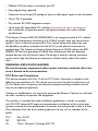
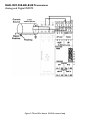
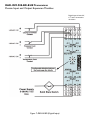
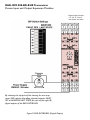
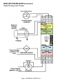
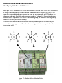
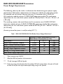
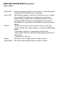
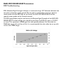
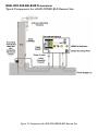
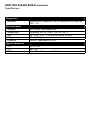
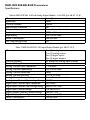
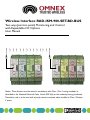
Wireless Interface RAD-ISM-900-SET-BD-BUS
Two-way (point-to-point) Monitoring and Control
with Expandable I/O Options
User Manual
) ) ) ) ) ) ) ) ) ) ) )
Notice: These devices must be wired in accordance with Class I, Div. 2 wiring methods as
described in the National Electrical Code, Article 501-4(b) or the authority having jurisdiction.
Transmitter unit is to be used with a purely resistive antenna when installed in Class I, Division
2 areas.
• Modular DIN-rail mount transceiver and I/O
• No programming required
• Maximum thirty-three (33) analog or sixty-six (66) digital signals in one direction
• Class I Div 2 approved
• Dry contact RF LINK diagnostics output
• Up to eight (8) expandable I/O modules (passive/active inputs and outputs)
per transceiver on common power and communications bus with multiple
combinations
The Phoenix Contact RAD-ISM-900-BD-BUS is an integrated radio & I/O module
designed for bidirectional interfacing of a 4-20mA current loop and two discrete
signals in harsh industrial environments. This unique design also allows the user
the flexibility to add on multiple channels of I/O to the paired transceivers in
combinations. The Frequency Hopping Spread Spectrum (FHSS) utilizes the 902928MHz ISM band to guarantee a license free, interference free link between
remote devices and the control room. The design is ideal for moving numerous
signals within high interference environments without costly cable and conduit
runs.
WARNING: EXPLOSION HAZARD
Do not disconnect equipment unless power has been switched off or the
area is known to be non-hazardous.
FCC Rules and Compliance
This device complies with Part 15 of the FCC Rules. Operation is subject to the
following two conditions: (1) This device may not cause harmful interference, and
(2) this device must accept any interference received, including interference that
may cause undesired operation.
Changes or modifications not expressly approved by Phoenix Contact Inc. will void
the user’s authority to operate the equipment.
This product is intended for fixed installation applications. In order to comply
with FCC/ISC adopted RF exposure requirements, installation of this transmitter
system’s antenna must be performed in a manner that will provide at least a 6 foot
(2m) clearance from the front radiating aperture to any user or member of the
public.
FCC
ISC
UL
Part 15.247
RSS 210
Class I, Division 2 (Groups A,B,C,D)
RAD-ISM-900-BD-BUS Transceiver
Analog and Digital INPUTS
Figure 1:Two-Wire device 4-20mA current loop
RAD-ISM-900-BD-BUS Transceiver
Analog and Digital INPUTS
Figure 2:Three-Wire device 4-20mA current loop
RAD-ISM-900-BD-BUS Transceiver
Analog and Digital INPUTS
Figure 3: Four-Wire device 4-20mA current loop
RAD-ISM-900-BD-BUS Transceiver
Analog and Digital OUTPUTS
Figure 4: Output Examples
RAD-ISM-900-BD-BUS Transceiver
RF Link and Choosing Output States
RF Link Output
The Link Status contact on the RAD-ISM-900-BD-BUS is Normally Open (NO) and
closes when the radio establishes an RF Link. It can be used to switch either a STATUS
light or a FAULT indicator.
Selecting State of Outputs Upon Loss of RF Link
The default state upon loss of RF signal for the analog and digital outputs is MAINTAIN
LAST STATE. They may be wired in series with the RF Link contact to provide a FAULT
OFF when RF Link is terminated.
RAD-ISM-900-BD-BUS Transceiver
Block Diagram
RAD-ISM-900-BD-BUS Transceiver
Passive Input and Output Expansion Modules
Analog input channel 4
connection not shown
Figure 5: RAD-IN-4A-I (Analog Input)
RAD-ISM-900-BD-BUS Transceiver
Passive Input and Output Expansion Modules
Analog
output channels 3 and 4
connections
not shown
By releasing the top part of the housing, the user may
access DIP switches that allow selection between FAULT
OFF or MAINTAIN LAST STATE for each of the four (4)
analog outputs of the RAD-OUT-4A-I.
Figure 6: RAD-OUT-4A-I (Analog Output)
RAD-ISM-900-BD-BUS Transceiver
Passive Input and Output Expansion Modules
Digital input channels 4,
6, 7 and 8 connections
not shown
Figure 7: RAD-IN-8D (Digital Input)
RAD-ISM-900-BD-BUS Transceiver
Passive Input and Output Expansion Modules
Digital output channels
1, 2, 3, 4, 6, 7 and 8
connections not shown
By releasing the top part of the housing, the user may
access DIP switches that allow selection between FAULT
OFF or MAINTAIN LAST STATE for each of the eight (8)
digital outputs of the RAD-OUT-8D-REL.
Figure 9: RAD-OUT-8D-REL (Digital Output)
RAD-ISM-900-BD-BUS Transceiver
Digital/Analog Input/Output
Figure 10: RAD-IN+OUT-2D-1A-I
RAD-ISM-900-BD-BUS Transceiver
Configuring I/O Module Addresses
Each pair of I/O modules, such as the RAD-IN-4A-I and the RAD-OUT-4A-I, must share
a unique module address. Once a module address has been assigned to a pair of I/O
modules, that module address may not be used on any other pair of I/O modules on
the same radio pair. Available addresses are numbers 1 through 8. If module addresses
conflict, or are improperly set within a connected group, an indication will be given by
the STATUS LED (see section below).
The RAD-ISM-900-BD-BUS Transceivers are designed to operate as matched pairs
and are factory programmed. Manual address configuration is not required for the
transceiver units.
Figure 11: Module Address Selection Switch
RAD-ISM-900-BD-BUS Transceiver
Power Budget Requirements
The following table may be used as a reference when determining your power supply
requirements. Total power requirements are shown per module, per side of the system.
For example, the transmitter side may have one (1) transceiver, one (1) RAD-IN4A-I expansion module and one (1) RAD-IN-8D expansion module. The total power
requirement for this side of the system would be 213mA [75mA + 26 mA + 32 mA + (4
x 20 mA)].
The matching receiver side would have one (1) transceiver, one (1) RAD-OUT-4A-I
expansion module and one (1) RAD-OUT-8D-REL expansion module. The total power
requirement for this side of the system would be 287 mA [75 mA + 100 mA + 32 mA +
(4 x 20 mA)].
(Assuming internal bus power is used for analog I/O****)
Table 1: RAD-ISM-900-BD-BUS Rail Builder Power Budget Worksheet*
Quantity X Power Requirement (in mA) =
Total Power Consumption (in mA)
Transceiver**
1
75 ***
75
Digital Input Expansion Module
8 max.
26
208
Digital Output Expansion Module
8 max.
100
800
Analog Input Expansion Module
8 max.
32
256
Analog Output Expansion Module
8 max.
32
256
Analog I/O Using Internal Power ****
8 max.
20
660
Total Power Supply Requirement (Sum of all devices used)
*
These currents are 24 VDC.
**
Allow for 200 mA peak on the transceiver
***
75 mA (average), 200 mA (peak)
**** If you are using internal power for the analog 4-20 mA current loops, then you will need
to add 20 mA for each input and output being using in this fashion.
RAD-ISM-900-BD-BUS Transceiver
Status LEDs
Power LED
Indicates presence of power to the device. It is ON when power
is present and OFF when there is no power.
Status LED
When flashing rapidly, it indicates an internal error or a module
type mismatch. A module type mismatch occurs when the
module address selection for two different modules (i.e. one
(1) digital module and one (1) analog module are set to the
same address or two (2) pairs of modules are sharing the same
address).
RF LED
• Flashes once every two seconds when there is no RF Link
• Flashes rapidly when signal strength is marginal (see RSSI graph
below)
• ON steady indicates an exceptionally strong RF Link
• Most systems will flash occasionally indicating the presence of
intermittent
interference in the area.
Digital
OFF means that the digital input or output is Open
Input/Output ON means that the digital input or output is Closed
RAD-ISM-900-BD-BUS Transceiver
RSSI Troubleshooting
RSSI (Received Signal Strength Indicator) is measured using a DC Voltmeter between the
test point and power supply ground. The test point is accessed by inserting a positive
meter probe into the RSSI hole on the face of the RAD-ISM-900-BD-BUS and the
negative meter probe to the Ground terminal.
The RSSI graph below may be used to test the Receive Signal Strength of the RAD-ISM900-BD-BUS. The ideal voltage that should be read from the RSSI test point is 2.5VDC
or more. This represents a 90dB signal loss and typically indicates that the radio has
20dB fade margin left until loss of link. It is recommended that the radios be set up with
no less than 20dB margin.
RAD-ISM-900-BD-BUS Transceiver
Typical Components for a RAD-ISM-BD-BUS Remote Site
Figure 12: Components for RAD-ISM-900-BD-BUS Remote Site
RAD-ISM-900-BD-BUS Transceiver
Ordering Information
Part Description
RAD-ISM-900-SET-BD-BUS-ANT (2-way transceiver with quarter-wave
whip antennas)
RAD-ISM-900-SET-BD-BUS (2-way transceiver without antennas)
RAD-IN-4A-I (4-channel analog input module)
RAD-OUT-4A-I (4-channel isolated analog output module)
RAD-IN-8D (8-channel digital input module)
RAD-OUT-8D-REL (8-channel digital output with relays)
RAD-IN+OUT-2D-1A-I (2 digital / 1 analog input/output module)
RAD-ISM-900-BD-BUS (can be used as spare or repeater; requires ID no.
of transceivers)
RAD-ISM-900-SET-UD-BUS (1-way system with 1 transmitter and 1
receiver only)
RAD-ISM-900-1TX-2RX-BUS (1-way system with1 transmitter and 2
receivers (expandable))
RAD-ISM-900-HOP-US (used to configure repeater(s) or replacement
transceivers)
RAD-ISM-900-ANT-4 (4-way splitter to cascade receivers in simplex
mode)
Part No.
28 67 27 0
28 67 08 9
28 67 11 5
28 67 12 8
28 67 14 4
28 67 15 7
28 67 32 2
28 67 09 2
28 67 56 8
28 67 57 1
28 67 53 9
28 67 05 0
RAD-ISM-900-BD-BUS Transceiver
Ordering Information
Accessories
Item
Part Description
Part No.
Antennas
RAD-ISM-900-ANT-OMNI-0-6 (¼ wave Omni antenna
28 67 16 0
with 6 feet of cable & MCX (M) connector)
RAD-ISM-900-ANT-OMNI-5 (5dB Omni base station,
Larsen FB35 T900, full ground plain with type N(F)
28 67 19 9
connector)
RAD-ISM-900-ANT-YAGI-6 (6dB Yagi, Larsen 3 element
28 67 20 9
with type N (F) connector)
Cables
RAD-CAB-RG213-50 (RG2130 - 50 feet with type N (M)
28 67 22 5
connectors) - cable loss = 7.6dB/100 feet
RAD-CAB-LMR400-100 (LMR400 - 100 feet with EZ400
28 67 23 8
NMH type N (M) connectors) - cable loss = 3.9db/100 feet
RAD-CAB-RG58-10 (RG58 - 10 feet with type N (M)
28 67 36 4
connectors) - cable loss = 16dB/100 feet
Adapters
RAD-CON -N-BNC-BS (N (F) to BNC (F) adapter)
28 67 24 1
RAD-CON-MCX-N-SS (MCX (M) to N (M) fitting with
26 27 25 4
48” of RG316 cable)
RAD-CON-MCX-BNC-SB (MCX (M) to BNC (F) with 24”
28 67 26 7
of RG174AU cable)
RAD-CON-SMA-N-SS (SMA (M) to N (M) with 48” of
28 67 40 3
RG316 cable)
RAD-CON-SMA-BNC-SB (SMA (M) to BNC (F) with 2’ of
28 67 72 0
RG174 cable)
Surge
CN-UB-280DC-BB (bulkhead mount COAXTRAB)
56 03 85 9
Arrestor
Other types and variations of accessories are available. Please contact your local
distributor or Phoenix Contact Inc. for more information.
RAD-ISM-900-BD-BUS Transceiver
Specifications
Table 2: RAD-ISM-900-BD-BUS (p/n 28 67 27 0)
General
Range
600 to 1,000 feet (180 to 305 m) in-plant (obstructed); 4-5
miles (6-8 km) LOS with Omni antenna; 20+ miles (32+ km)
LOS with Yagi antenna
Inputs
One (1) 4-20 mA analog input (16-bit, 125 ohms impedence)
Two (2) digital inputs (5-30 VDC)
Outputs
One (1) 4-20 mA analog input (16-bit, short-circuit
protected)
Two (2) digital inputs (dry contact, NO, contact rating: 250
VAC/2 A)
I/O Expansion Capacity Four (4) analog and eight (8) digital I/O modules
Repeatability
Current loop: 0.02%
Accuracy
Current loop: 0.2% of full scale at 77°F (25°C)
Wiring Connections
12-24 AWG screw-type terminals; removable terminal
blocks
Mounting
DIN-rail mount
Primary Power
Input Voltage
9 to 30 VDC
Reverse Polarity
Yes
Protection
Surge Protection
Yes
Power Consumption
75mA (avg)/200mA (peak) @ 24VDC during transmission
(plus I/O modules)
Transceiver
Frequency
902 to 928 MHz - ISM band
Transmit Power
1 Watt (30 dBm)
RX Sensitivity
-110dBm
Unit ID
Factory configured (unique); 16-bit coding of each
transceiver pair allows multiple units to be used in the same
area
Antenna Connector
MCX female
Antenna Impedence
50 ohms
RAD-ISM-900-BD-BUS Transceiver
Specifications
Diagnostics
Indicators
Environmental
Humidity
Temperature
Size
Weight
Enclosure
Agency Approvals
FCC
ISC
UL/C
External LEDs (power, RF link, I/O status)/RF link relay 250
VAC / 2 A
20% to 90% (non-condensing)
Operating: -40° to +158°F (-40° to +70°C)
4.5” x 3.9” x 0.9” (114 mm x 99 mm x 23 mm)
5.3 oz (150 g)
NEMA 1 (equivalent to IP20)
Part 15.247
RSS 210
Class I, Div. 2 (Groups A, B, C, D)
RAD-ISM-900-BD-BUS Transceiver
Specifications
Table 3: RAD-IN-8D Digital Input Module - Low Volt (p/n 28 67 14 4)
Channels
Input Voltage Range
Input Impedence
Channel Isolation
Reverse Polarity Protection
Over-voltage Rating
Power Consumption
Eight (8)
5 to 30 VAC/DC
20 K ohms
Optical
Yes
100 VAC/DC max.
30 mA max.
Table 4: RAD-OUT-8D-REL Digital Output Module - 8-ch Relay (p/n 28 67 15 7)
Channels
Output Terminals
Contact Ratings
Channel Isolation
Power Consumption
Eight (8)
Dry contact (NO)
250 VAC / 2 A
Full
160 mA max.
Table 5: RAD-IN-4A-I 4-20 mA Analog Input Module - 4-ch (p/n 28 67 11 5)
Channels
Resolution
Input Impedence
Channel Isolation
Reverse Polarity Protection
Compatability
Over-voltage Rating
Accuracy
Repeatability
Power Consumption
Four (4)
16-bit
< 170 ohms
None (power supply connections are
common with tranceivers)
Yes
2-wire, 3-wire, 4-wire devices
42 VDC max.
0.2% of full scale
0.02% of full scale
130 mA max.
RAD-ISM-900-BD-BUS Transceiver
Specifications
Table 6: RAD-OUT-4A-I 4-20 mA Analog Output Module - 4-ch ISOL (p/n 28 67 12 8)
Channels
Resolution
Channel Isolation
Short-circuit Protection
Compatability
Accuracy
Repeatability
Power Consumption
Min. Loop Voltage Drop
Four (4)
16-bit
Optical
Yes
2-wire, 3-wire, 4-wire devices
0.12% of full scale
0.02% of full scale
130 mA max.
10 V
Table 7: RAD-IN+OUT-2D-1A-I Input/Output Module (p/n 28 67 32 2)
Channels
One (1) analog input
One (1) analog output
Two (2) digital inputs
Two (2) digital outputs
Channel Isolation
All (except for analog input channel)
Reverse Polarity Protection
Yes
Analog Channel Input Impedence
< 170 ohms
Analog Channel Repeatability
0.02% of full scale
Analog Channel Resolution
16-bit
Analog Channel Accuracy
0.2% of full scale
Analog Channel Compatability
2-wire, 3-wire, 4-wire devices
Analog Input Channel Over-voltage Rating 42 VDC max,
Digital Input Channel Input Impedence
20 K ohms
Digital Input Channel Over-voltage Rating 100 VAC/DC max.
Digital Input Channel Voltage
5 to 30 VAC/DC
Digital Output Channel Contact Ratings
250 VAC / 2 A
Digital Output Channel Type
Dry contact (NO)
Power Consumption
120 mA max.
USA
Phoenix Contact Inc.
P.O. Box 4100
Harrisburg, PA 17111-0100
Phone:
800-888-7388
717-944-1300
Technical Service:
800-322-3225
Fax:
717-944-1625
E-mail:
[email protected]
Website:
www.phoenixcon.com
Omnex Controls
Corporate Headquarters
74-1833 Coast Meridian Road
Port Coquitlam, BC V3C 6G5
Phone:
604-944-9247
Fax:
604-944-9267
Email:
[email protected]
Website: www.omnexcontrols.com
© 2004 Phoenix Contact Inc.
L001662:11.04
Canada
Phoenix Contact Ltd.
235 Watline Avenue
Missisauga, Ontario L4Z 1P3
Phone:
905-890-2820
Technical Service:
800-890-2820
Fax:
905-890-0180
E-mail:
[email protected]
Website:
www.phoenixcon.com