1
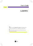
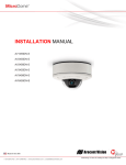
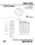
P
PPC19W-4
45GM
M Barrebon
ne
Userr’s Quick Sttart Card
V
Version
1.00
Portts
h
http://www.b
bcmcom.com
m
Insp
pect the Package:
One P
PPC19W-45GM
M Barebone
One P
Power Adaptorr
One P
Power Cord (US
S)
One H
Heatpipe
One S
SATA CD ROM Adaptor
One P
Pack of Screws
s
One D
Driver CD/DVD
One U
User’s Quick Start Card
Resp
ponsibility:
This m
manual is proviided “As-Is” with no warrantiess of any kind, e
expressed or im
mplied, including
g, but not limite
ed to the
implie
ed warranties orr conditions of th
his product’s fitn
ness for any pa
articular purpose
e. In no event sh
hall we be liable
e for any
loss o
of profits, loss of
o business, losss of data, interrruption of business, or indirecct, special, incid
dental, or conse
equential
dama
ages of any kind
d, even the posssibility of such damages arising from any defecct or error in thiss manual or prod
duct. We
reservve the right to m
modify and updatte the user man
nual without prior notice.
Fun
nction Buttoons
W
WARNING: C
CMOS Batte
ery Damage
Repla
ace your system
m’s CMOS RAM battery only with the identical CR-2032
C
3V Lith
hium-Ion coin ce
ell (or equivalentt) battery
type to
t avoid risk of personal injury or physical dam
mage to your eq
quipment. Impro
oper installation
n might cause b
battery to
explode. Always dispose of used batteries
b
accord
ding to the ma
anufacturer’s insstructions, or ass required by the
t
local
ordina
ance (where ap
pplicable). The damage due to
o not following th
his warning will void your moth
herboard’s manu
ufacturer
warra
anty.
Perch
hlorate Material-- Special Handlin
ng May Apply.
See h
http://www.dtsc.cca.gov/hazardou
uswaste/perchlo
orate/
Additional Inforrmation:
Additiional information
n on setting thiss board up can be found in the User’s Manual in the provided CD or DVD RO
OM. The
Online
e User’s Man
nual and FAQ
Q/Knowledge B
Base can be found on our website by visiting our website:
ur forums and p
http:///www.bcmcom
m.com. If your q
question is not answered
a
in ourr FAQ/Knowledg
ge Base, visit ou
post your
messages or submit a new FAQ thro
ough FAQ Subm
mittal form for us to add your que
estion in our FA
AQ with our answ
wer.
A
ATTENTION
N: Incorrect B
BIOS Setup
If you
u do not know how to handle BIOS setup or ho
ow to set it up p
properly, it is strrongly advisable
e that you do no
ot modify
any o
of the settings th
han otherwise instructed in the U
User’s Quick Sta
art Card. Even a seemingly sm
mall incorrect adjjustment
or mo
odification in the
e BIOS setup ca
an render your ssystem unstable
e or unusable. IIncorrect BIOS setup is not covvered by
your motherboard’s
m
m
manufacturer wa
arranty. Try Cle
ear CMOS inform
mation when sysstem does not boot
b
after BIOS settings
chang
ge.
Poweer button: Turnn on and off thhe unit.
Voluume “+”: Increease the audio volume outpuut
Voluume “-“: Decreease the audio volume outpuut
D panel
Brighhtness “+”: Inccrease the brigghtness of LCD
Brighhtness “-“: Deecrease the brigghtness of LC
CD panel
How
w to access inside the u
unit to instaall CPU, memory,
m
...
1.
Take out the M3 screw from the stannd with 2 lb-in or less.
CPU
U and Heattpipe Installlation
This processor is inntended to be professionallyy installed. Taake proper elecctrostatics disccharge (ESD)
precaautions such aas using approppriate ground strips, gloves,, and ESD matts.
1. Place the CPU on top of the socket.. Make sure tto
align the ggold arrow on the CPU withh the arrow keey
on the sockket.
2
2.
Take out the plastic staand cover and take out 4x #66-32 screws frrom the metall stand with 3 lb-in or
less.
2. Push the CPU down unntil its pins seecurely fit intto
the socket..
3
3.
Take out 4x #6-32 screw
ws from four corners with 3 lb-in or less.
3. On the front
f
end of tthe CPU soccket is a lockking
mechanism
m designed innto the form oof a screw. M
Make
sure that you actuate or
o de-actuate this mechanism
with a screewdriver beforre and after installing the CP
PU.
4
4.
Open up the
t plastic bacck cover. Takee out 10x M3 sscrews from thhe back cover with 3 lb-in oor less.
U die. Lock doown
4. Place the hheatpipe evennly on the CPU
the screwss in 4 corners with 2 lb-in or less onto ppreinstalled back bracket.