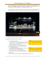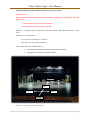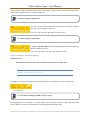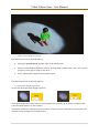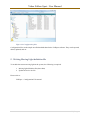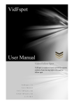
1
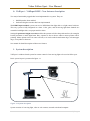
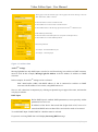
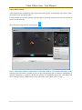
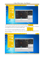
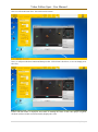
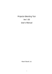
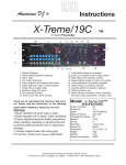
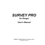
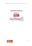
VidFspot User Manual Video Follow Spot VidFspot is windows based system for remote control of one moving light to be used as follow spot. VidFspot- V2 User Manual www.vidFspot.com [email protected] 2/17/2015 Video Follow Spot - User Manual VidFspot 0. VidFspot – VidFspot DMX - New features description .................................................................. 2 1. System description .......................................................................................................................... 2 2. Software installation ........................................................................................................................ 4 3. System setup .................................................................................................................................... 8 3.1. System configuration ........................................................................................................... 8 3.2 Tracking calibration (Pan Tilt) .......................................................................................... 15 3.3. Tracking............................................................................................................................. 20 3.4. Dimmer, Iris, Zoom Focus Calibration (VidFspot V2 ) .................................................... 23 4. Configuration files ......................................................................................................................... 25 5. Writing Moving Light definition file ............................................................................................ 26 1. | P a g e Video Follow Spot - User Manual 0. VidFspot – VidFspot DMX - New features description Two major functionality upgrade has been implemented in a system. They are: 1. DMX Input has been enabled. 2. Performer height correction has been implemented. With DMX input enabled, system can receive DXM data from light desk or a light control software. This way system is fully integrated in a show. Color, gobo, and all moving light dmx channels are controlled with light desk, except pan and tilt values. Setting the performer height correction enables the operator to follow the performer feet (for example) but the performer is inside light beam. Here, operator is free to choose where a mouse pointer will be pointing. Mouse pointer can be in center of beam, or it can be at the beam bottom edge, or beam upper edge, or anywhere in between. See manual for detail description of these two features. 1. System description VidFspot is windows based system for remote control of one moving light to be used as follow spot. Basic system layout is presented in figure 1.1. Figure 1.1 System description System consists of a moving light, video or web camera, network switch and computer. 2. | P a g e Video Follow Spot - User Manual Computer and a moving light are connected via ArtNetTMTM network. Video camera (or web camera) is mounted in such position to give overall view of the stage, and video from that camera, is displayed on a computer screen, as shown on figure 1.2. Video camera must be mounted in the same direction with a moving light, moving light and a camera were mounted beside each other. See figure 1.1. Here we are using our “Lego Stage”. Before stage performer can be tracked, camera angle must be measured and a moving light must be calibrated. Moving light calibration procedure is needed for calibration of pan and tilt values. Video camera angle toward the stage must also be measured (see VidFspot - Camera angle PDF). Other moving light parameters such as Dimmer, Iris, Focus and Zoom values can also be calibrated and controlled with the VidFspot software (V2). After this calibration procedure, stage performer can be tracked using the pc mouse, trackpad, trackball or any other pc input device. VidFspot software is divided in a three functional steps that needs to be set up prior to tracking. They are: 1. System Configuration – purpose of this step is to connect the vidFspot system with moving light and video camera. VidFspot must be configured to control the moving light (IP address, DMX universe, etc). For example, setting the moving light channels values and macros (lamp on, shutter open, dimmer, etc.). And also, video camera must have a video player software installed that will display the video on a computer screen. 2. Camera angle measuring - Camera angle towards the ground must be measured and also camera horizontal field of view must be measured. 3. Moving Light Calibration – simple, two point calibration procedure to calibrate the moving light. 3. | P a g e Video Follow Spot - User Manual Figure 1.2 LegoTM city - View from a camera. As already stated, tracking the stage performer with a moving light is done with pc mouse. Operator is moving the mouse pointer on the computer screen thus directing the moving light in a position on the stage where pointer is pointing. This way moving light is controlled as a remotely controlled follow spot. There are no restrictions regarding moving light placement. It can be placed anywhere above the stage. Moving light parameters that are implemented are: Tilt, Tilt fine Pan, Pan fine Iris (to be implemented V2) Dimmer (to be implemented V2) Zoom (to be implemented V2) Focus (to be implemented V2) 2. Software installation For its work, VidFspot software is using configuration files that are stored in “C:\VidFspot” folder. Prior to installing the VidFspot software, you must first: 1. Download configuration files and extract them to VidFspot folder on c: drive. 4. | P a g e Video Follow Spot - User Manual Figure 2.1.“C\VidFspot” folder. In case of missing VidFspot folder on c: drive following program error will occur, and the program will end. 2. Install the VidFspot software package. 3. Connect the Moving light and PC with a Cat 5 cable via network switch. Use ArtrnetTM to DMX converter if moving light does not support ArtNetTM 4. Start video player software. 5. | P a g e Video Follow Spot - User Manual Figure 2.2.Video player or Webcam player software. 5. Start the VidFspot application. Figure 2.2.VidFspot software. 6. | P a g e Video Follow Spot - User Manual VidFspot software has a transparent user interface with top toolbar and bottom status toolbar. Program is “on top” of all other opened programs and it does not allow operator to click on desktop icons. To switch between the programs use “Alt Tab” combination. To allow the user to use icons on desktop, SPOTRACK image (upper left corner) must be pressed. Program will “Close” transparent part and it will join toolbar and status bar together. Now user can access the windows OS. Pressing the Spotrack image again will activate transparency. Toolbar menus: This toolbar holds the following settings: System settings - Selects the type of moving light to be used for tracking. Set the ArtNetTM data and set the video parameters data. Moving light settings - Set the DMX channel values and records the macros. Macro list – View and manipulate with macro list Calibration - Set the calibration settings. Activate the DMX – Activate the DMX output. (Shortcut – key A) Tracking – Activate the tracking output. (Shortcut – key T) Dimmer – Activate the automated dimmer with tracking. (Shortcut - key D) Iris – Activate the automated iris with tracking. (Shortcut – key I) Zoom – Activate the automated zooming with tracking. (Shortcut – key Z) Focus– Activate the automated focusing with tracking. (Shortcut – key F) Macro – Activate the macro functionality. (Shortcut – key M) Status bar menus: This toolbar holds the current mouse pointer coordinates, but only when DMX output is activated. And, in a program trial version, this toolbar holds the number of minutes that program can be used. After this period program must be restarted. Macro: Macros are predefined DMX values. They are defined by the user in macro settings. 7. | P a g e Video Follow Spot - User Manual 3. System setup 3.1. System configuration VidFspot uses ArtNetTM protocol to communicate with the moving light. Before program is started computer IP address must be set accordingly to ArtNetTM specification. In this example we have set the computer IP address to 2.168.33.100 When VidFspot software is started, a communication between PC and a moving light must be established. 6. Set the computer IP address and Subnet mask to ArtNet settings. Pictures above shows the computer IP address and Subnet mask as well as VidFspot program IP address DMX universe and DMX address example. It would be better that computer IP address is more “closer” to IP address of the ArtnetTM to DMX converter, for example 2.100.100.50, but this will also work. 7. Click on the system Settings button System settings parameters are explained on the figure 3.1. As seen on the figure there are three types of settings to be set. 1. Moving Light selection 2. ArtNetTM settings 3. Video camera settings 8. | P a g e Video Follow Spot - User Manual “Moving light” combo box holds the type of moving light to be used for tracking. In this case “MAC 2000 Profile (16Bit)” is selected. Write the IP address of ArtnetTM to DMX converter. Write the DMX Universe of the ArtnetTM to DMX converter. Write the DMX Address of the Moving Light connected to ArtnetTM to DMX converter. Enable DMX input functionality. Write the IP address of the DMX input device (Computer or DMX input device). Write the DMX Universe of the DMX input device. Video frame parameters. see VidFspot – HorizontalFieldofView.pdf see VidFspot – CameraAngle.pdf Figure 3.1 ArtNetTM data. ArtNetTM settings Moving light that has only DMX input, can also be used for tracking, but ArtNetTM to DMX converter must be used. In this example, Moving Light IP Address is the IP Address of ArtNetTM to DMX converter. In this example, for ArtNetTM settings we have selected: MAC 2000 Profile (16Bit) with DMX address of 100 is connected to ArtNetTM to DMX converter with IP address 2.192.124.84, using DMX universe 3. Now we will “deactivate” transparency by clicking on Spotrack logo in upper left corner, and start the web player software. DMX Input Before DMX input is enabled, DMX parameters (or more precisely ArtNet parameter) have to be set. IP Address of the device that sends data (Light desk or PC) have to be entered and DMX universe that will be received also needs to be entered. To enable DMX input “Enable DMX in” checkbox must be selected. If system is receiving DMX data it will display Receiving DMX message. 9. | P a g e Video Follow Spot - User Manual Video camera settings Video camera frame is defined by upper right and lower left points. To define this video frame, camera do not have to be mounted in studio. For this example we will use Logitech C910 web camera. As already stated, but any video or web camera can be used for tracking. We will activate Logitech web camera player. Here a video player software is showed and a video frame inside it. We will place this player on the desktop at our convenience, and then we have to press the Spotrack logo to return the transparency to desktop. Transparency is needed to disable the operator to accidentally click on the video player and move it during tracking. Transparency is only active when Aero scheme (win 7) is ON. 10. | P a g e Video Follow Spot - User Manual Now we will activate the DMX by pressing Activate DMX checkbox. Activating DMX is mandatory for the system to mark the upper right and lower left points. At this point moving light does not have to be connected to DMX output. Now we will select “Screen Upper Right Corner” option box. Now we will move a mouse pointer at the upper right corner of the frame that is displaying the video and press ctrl button. 11. | P a g e Video Follow Spot - User Manual Now we will do the same for a “Screen lower left corner”. Now, we will press the Save button and then press the “Video frame” check box, or we can simply press the v key. Frame with red border is displayed. This frame is marking the frame of the video player (Logitech Webcam software in this case) that actually displays the video. 12. | P a g e Video Follow Spot - User Manual This is the frame that VidFspot software is looking for, part of the desktop where actual video is displayed. Now we can connect the moving light to the DMX output and configure it for tracking. To set the moving light parameters, select the “Moving Light Settings” button. 8. Click on the Moving Light Settings button. This button will open a new frame that is shown here (figure 3.2.). Figure 3.2 DMX values and Macro settings. Here, moving light DMX parameters are set. Selecting a moving light channel on the left side of the frame (Channel frame), will open selected channel details, on right side of the frame (Channel values frame), figure 3.3. 13. | P a g e Video Follow Spot - User Manual Figure 3.3 Channel 1 values. Selecting channel 1, all the values for channel 1 are displayed in list box on the Channel values frame. See figure 3.4. Figure 3.4 Lamp power on. Frame “Save as default DMX Value” on the upper right side, holds the selected channel’s DMX address, and selected channel’s saved value. In this case, channel 1 value is set to value 228 (Lamp power on). See figure 3.4. If value needs to be changed (for example, to “Shutter Open” value), Shutter Open must be clicked inside Channel values frame. Then, the program will change DMX values accordingly. Note: Program will send DMX data to the moving light only when Activate DMX check box is selected. When moving light DMX channel values are set (shutter open, dimmer, iris, zoom, etc), this values will be saved as a default values by pressing the “Save” button in Save as default DMX values. This “Save” button the saves all DXM channel values for a selected moving light. This values are loaded when the program starts. Save button in “Save as Macro” frame will also save DMX values for selected moving light but it will save them as a macro file. These values can be called during tracking and be trigged as macro. Macro that opens the shutter, macro that closes the shutter, macro that places gobo, color, and etc, are some of the examples of macros that can be used during the show. 14. | P a g e Video Follow Spot - User Manual 3.2 Tracking calibration (Pan Tilt) Note: During calibration procedure gobo can be used but it is not mandatory. It is recommended that following channel values are set to start with: Tilt = 128 Tilt fine = 128 Pan = 128 Pan Fine = 128 Use gobo (for example, Martin MAC 2000 – Inverted King Star) Adjust focus to have clear gobo projection on the floor. System calibration procedure has two functions. 1. Moving Light Rotation checkbox, Tilt and Tilt Fine parameters has to be adjusted, the so that moving light is in vertical position towards the ground. See figure 3.6. 2. Point 1. And Point 2. Defines the values of pan and tilt in these two points. 7. Click the Calibration button on program toolbar Calibration frame is shown on figure 3.5., it holds two functions. Rotate function Calibration function Figure 3.5. Calibrate form. 3.2.1. Rotation function By activating “Rotate” function, VidFspot software for Tilt and Tilt fine values will use values from a Rotating function frame (Tilt=128, Tilt Fine=36, in this example, see figure 3.5). Pan value is automatically changed from value 0 to value 255, in equal time intervals. Time interval for this function is defined by “Speed +/-”. So, this function will rotate moving light using only pan value. Purpose of this function is to adjust the Tilt and Tilt Fine values where moving light is positioned vertically towards the ground. For this we can use gobo or use zoom and iris to make the smallest circle on the floor. 15. | P a g e Video Follow Spot - User Manual Figure 3.6. Moving light position using the Rotate function. Gobo is selected on a moving light, for example, figure 3.8. shows suitable type of gobo projection on the floor. Figure 3.7.Inverted King Star gobo. 8. Check the “Moving Light Rotation” checkbox. Change Tilt and Tilt fine values, until the center of gobo, and gobo itself, is not making circles on the floor, or making small circles. For example, tilt and tilt fine values, shown on figure 3.8, have set the moving light in a vertical position towards the floor. Moving light with Tilt value of 127 and Tilt fine value of 150 is making smallest circle of a gobo projection on a floor. 16. | P a g e Video Follow Spot - User Manual Figure 3.8.Moving light vertical position. Note ! If the moving light is not making full circle, when rotate function is activated, raise the value of “Speed +/-”. 9. Uncheck the “Moving Light Rotation” checkbox. 3.2.1. Pan Tilt calibration Procedure for system calibration is rather simple one. 1. Check Point 1 checkbox. 2. Change Tilt, Tilt Fine, Pan and Pan Fine values to move the moving head to the point at the beginning of the stage. 3. Check Point 2 checkbox. 4. Change only Tilt, Tilt Fine values to move the moving head to the point at the end of the stage. Point 1. Point 2. Point 1 is always the point that is closer to moving light. Figure 3.10.shows one typical stage. Calibration points (Point 1 and Point 2) are marked on the figure. Point 1. – is point in front of the stage. Point 2. – is point in back of the stage. 17. | P a g e Video Follow Spot - User Manual It is recommended (but not required) that Point 1 and Point 2 are in the middle of the stage, if the moving light is mounted in “top center position in front of the stage”. This way we will have symmetrical tracking system, regarding Tilt and Pan values. If a moving light is mounted on the right side of the stage (looking towards the stage), recommended point 1 and point 2 positions are showed on figure 3.10 marked with red color. Point 2. Point 2. Point 1. Point 1. Figure 3.10. Point 1. and Point 2. settings. Moving light calibration procedure has two steps: 1. Check Point 1 optionbox. 2. Use Tilt, Tilt fine, Pan and Pan fine values to move light center in Point 1. It is recommended that this point is beginning off stage (see figure 3.10). 3. Move a mouse pointer in center of the light beam. 4. Press ctrl key. Point 1 text in radio box will turn red. 5. Check Point 2 optionbox. 6. Using only Tilt and Tilt Fine values, move the moving light in Point 2. “end –back of the stage”. 7. Move a mouse pointer in center of the light beam. 8. Press ctrl key. Point 2 text in radio box will turn red. 9. Press Save. 10. Point 1. and Point 2 text will turn black indicating that values are saved. 18. | P a g e Video Follow Spot - User Manual VidFspot software is fully calibrated using only these two points. Important note: During calibration positive direction must be achieved. Following is obligatory for a moving light values: 1. Tilt value must rise from Point 1 to Point 2. 2. Pan value must rise in clockwise direction. Figure3.11. is showing positive direction of tilt value, positive and negative directions of pan value. Therefore, it is required that: Tilt value rises from Point 1. to Point 2. Pan value rises in clockwise direction These requirements are fulfilled either by: inverting the Tilt channel or/and inverting the Pan channel rotating the moving light using Pan channel Point 2. Tilt (+) Pan (-) Pan (+) Point 1. Figure 3.11.Point 1.And Point 2.settings. 19. | P a g e Video Follow Spot - User Manual After saving tilt and pan parameters for Point 1 and Point 2, values can be check by selecting Point 1 and Point 2 option box. In this examples values are: 10. Select “Point 1” option box. Use Tilt, Tilt Fine, Pan and Pan Fine to position moving light in front of the stage. In this example values are: Tilt (156), Tilt Fine (36), Pan (200), Pan Fine (210) 11. Select “Point 2” option box. Changing only Tilt values, position moving light at the back of the stage. In this example values are: Tilt (166), Tilt Fine (113), Pan (200), Pan Fine (210) Figure 3.12.Point 1.And Point 2.settings. Important Note: Pan and Pan Fine values in Point 1 and Point 2 must have the same value. System is now configured for tracking. Tracking is activated by checking the tracking checkbox or by pressing the T key on keyboard. 3.3. Tracking 12. Check the Tracking checkbox or press T key. Moving light is now controlled as a remote follow spot, using the pc mouse pointer position on the screen. Mouse movements are translated to a moving light pan and tilt values. 20. | P a g e Video Follow Spot - User Manual Figure 3.14.VidFspot tracking. Pan and tilt speed can be adjusted either by Setting the “pan/tilt speed” channel value of the moving light. Macros can also hold the different values of “pan/tilt speed” channel value. (Fast, slow, normal speed for various type of songs in one show.) Or by, adjusting the computer mouse pointer speed. Pan and tilt speed can be adjusted either by 3.4. Performer height correction System can adjust performer height correction. These photographs shows that system is moving light beam vertically (up or down) according to the value entered in numeric up down control. This feature enables the followspot operator to place a mouse icon on a performer feet and system will direct the center of beam to be at right position. 21. | P a g e Video Follow Spot - User Manual 22. | P a g e Video Follow Spot - User Manual 3.5. Dimmer, Iris, Zoom Focus Calibration (VidFspot V2 ) Dimmer, Iris, Zoom and Focus calibration is also two point calibration. Here we are using Point 3 and Point 4 points just to distinguish them from Point 1 and Point 2. All that has been sad for point 1 and point 2 can also be sad for point 3 and point 4, with one difference: Point 3 and point 4 can be anywhere on the stage. Point 3 does not have to be at the beginning of the stage and Point 4 does not have to be at the end of the stage. Procedure for system calibration is rather simple one. 1. Check Activate DMX checkbox. 2. Check Tracking checkbox, manually change pan and tilt values. 3. Check Point 3 option box. 4. Move a mouse so that moving light on position on the stage. 5. Press ctrl button. Pressing the ctrl button current mouse coordinates will be saved. 6. Press key T. Pressing the T key Tracking is deactivated. 7. Check Point 4 option box. 8. Change only Tilt value to move the moving head in another point on the stage. This will be point 4 value. 9. Press ctrl button. Pressing the ctrl button current mouse coordinates will be saved. 10. Save. With this procedure we have defined point 3 and Point 4 coordinates. Now, when Point 3 or Point 4 option box is selected moving light will be set in that position. 23. | P a g e Point 3. Point 4. Video Follow Spot - User Manual Note: Point 3 must always the point that is closer to moving light. 13. Select “Point 3” option box. 11. Check Point 3 option box. Moving light will be position in position of point 3. 12. Set the value of dimmer. 13. Set the limit value. System will not go below this value. 14. Select “Point 4” option box. 14. Check Point 4 option box. Moving light will be position in position of point 4. 15. Set the value of dimmer. 16. Set the limit value. System will not go above this value. 15. Select “Save”. System is now configured for automated dimming while tracking. Automated dimming during tracking is activated by checking the dimmer checkbox or by pressing the D key on keyboard. 24. | P a g e Video Follow Spot - User Manual 4. Configuration files VidFspot software requires that configuration files are placed in “C\VidFspot” folder. Figure 4.1.Configuration folder. Inside the VifFspot folder there is one folder (Macro) and number of files. 25. | P a g e Video Follow Spot - User Manual Figure 4.2.Configuration files. Configuration files are the simple text file that holds data for the VidFspot software. They can be opened, edited, updated, and etc. 5. Writing Moving Light definition file To include the custom moving light in the system, the following is required: 1. Moving light definition file (dmx chart) 2. Update in Device list file Please refer to: VidFspot – Configuration File manual. 26. | P a g e Video Follow Spot - User Manual VidFspot User Manual V2 www.spotrack.com [email protected] 5/20/2015 27. | P a g e