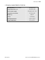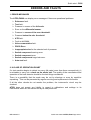
1
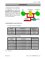
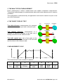
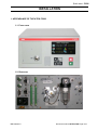
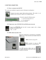
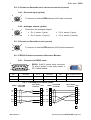
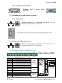
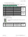
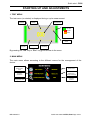
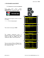
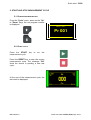
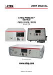
QUICK START
ATEQ F620
Version 1.0
(Photo no contractual)
Reference: MR-28300A-U
REVISIONS OF THE ATEQ F620 USER MANUAL
Due to continuing improvements, the information contained in this user manual, the features and design of
this device are subject to be changed without prior notice.
Edition/Revision
First edition
Reference
Date
Week/Year
Chapters up dating
MR-28300A-U
46/2012
-----
Quick start - F620
Quick start manual
TABLE OF CONTENTS
TABLE OF CONTENTS .................................................................................................. 1
PREAMBULE.................................................................................................................. 2
1. DEFINITION OF THE ATEQ F620 ......................................................................................................2
2. MEASUREMENT CHARACTERISTICS..............................................................................................2
3. THE MAIN TYPES OF MEASUREMENT............................................................................................3
4. THE THREE TYPES OF TEST ............................................................................................................3
5. MEASUREMENT CYCLE ....................................................................................................................3
INSTALLATION .............................................................................................................. 4
1. APPEARANCE OF THE ATEQ F5200................................................................................................4
2. ELECTRICS CONNECTORS ..............................................................................................................5
3. PNEUMATIC SUPPLY.........................................................................................................................9
4. PNEUMATIC CONNECTORS ...........................................................................................................10
USER INTERFACES..................................................................................................... 11
1. CYCLE KEYS ....................................................................................................................................11
2. TOUCHES DE NAVIGATION ............................................................................................................11
STARTING UP AND ADJUSTMENTS.......................................................................... 13
1. TEST MENU.......................................................................................................................................13
2. MAIN MENU.......................................................................................................................................13
3. PROGRAMMES MANAGEMENT .....................................................................................................14
4. PARAMETERS ..................................................................................................................................15
5. START AND STOP MEASUREMENT CYCLE .................................................................................16
6. FUNCTIONS ......................................................................................................................................17
OTHERS MENUS.......................................................................................................... 18
1. SPECIAL CYCLES ............................................................................................................................18
2. MENU CONFIGURATION .................................................................................................................19
3. SERVICE MENU MAINTENANCE ....................................................................................................20
4. RESULTS MENU ...............................................................................................................................20
5. USB MENU ........................................................................................................................................20
ACCESSORIES AND CHARACTERISTICS................................................................. 21
1. ACCESSORIES PROVIDED .............................................................................................................21
2. ACCESSORIES IN OPTION..............................................................................................................21
3. TECHNICAL CHARACTERISTIC OF THE F620 ..............................................................................22
ERRORS AND FAULTS ............................................................................................... 23
1. ERROR MESSAGES .........................................................................................................................23
2. IN CASE OF OPERATION DOUBT ..................................................................................................23
INDEX ........................................................................................................................... 24
Due to continuing improvements, the information contained in this user manual,
the features and design of this device are subject to be changed without prior
notice.
MR-28300A-U
Quick start manual ATEQ F620 Page 1/24
Quick start - F620
PREAMBULE
1. DEFINITION OF THE ATEQ F620
TEST
PART
The ATEQ F620 is a compact air/air
leak detector used to test the airtightness of parts. The method used
is based on the measurement of a
small variation or drop in differential
pressure between the test and
reference parts, when both are filled
to an identical pressure.
DIFFERENTIAL
SENSOR
REFERENCE
PART
TEST
PRESSURE
PIEZO
SENSOR
2. MEASUREMENT CHARACTERISTICS
2.1. PRESSURE DROP MEASUREMENT
RANGE
ACCURACY
RESOLUTION
Maximum
0 – 50 Pa
+/- (2,5% of the pressure + 1 Pa)
0,01 Pa
0 – 500 Pa
+/- (2,5% of the pressure + 1 Pa)
0,1 Pa
0 – 5000 Pa
+/- (2,5% of the pressure + 10 Pa)
1 Pa
2.2. TEST PRESSURE MEASUREMENT
RANGE
ACCURACY
RESOLUTION
Maximum
F.S. = 75 mbar*
+/- (1,5% of the pressure+ 0,2 hPa)
0,1 % F.S.
F.S. < 0,3 bar
+/- (1,5% of the pressure + 1 hPa)
0,1 % F.S.
0,3 ≤ F.S. ≤ 1 bar
+/- (1,5% of the pressure + 3 hPa)
0,1 % F.S.
1 < F.S. ≤ 5 bar
+/- (1,5% of the pressure + 7.5 hPa)
0,1 % F.S.
5 < F.S. ≤ 10 bar
+/- (1,5% of the pressure + 15 hPa)
0,1 % F.S.
10 < F.S. ≤ 20 bar
* Specific (relative)
+/- (1,5% of the pressure + 30 hPa)
0,1 % F.S.
F.S. = Full scale.
MR-28300A-U
Quick start manual ATEQ F620 Page 2/24
Quick start - F620
3. THE MAIN TYPES OF MEASUREMENT
Direct measurement, indirect measurement and sealed component measurement.
These three methods apply to measurements taken both under pressure and in vacuum
conditions.
The configuration is determined by the application and must be carried out prior to the
use of the instrument.
4. THE THREE TYPES OF TEST
Test with reference: measurement of a pressure
variation between a test part and a reference part.
Test without reference: measurement of a
variation in pressure between a test part and a
sealing connector on the reference side.
TEST
PART
DIFFERENTIAL
SENSOR
TEST
PART
DIFFERENTIAL
SENSOR
REFERENCE
PART
CAP
TEST
PART
Test with central zero: test of two parts at the
same time. One part is connected to the test side
and the other to the reference side.
DIFFERENTIAL
SENSOR
TEST
PART
5. MEASUREMENT CYCLE
WAIT
FILL
STABILIZATION
TEST
DUMP
The measurement cycle consists of 5 phases:
Start
1
2
3
4
5
Coupling
time
Fill time
Stabilization
time
Test
time
Dump
time
MR-28300A-U
Cycle
end
Quick start manual ATEQ F620 Page 3/24
Quick start - F620
INSTALLATION
1. APPEARANCE OF THE ATEQ F5200
1.1. FRONT FACE
1.2. REAR SIDE
MR-28300A-U
Quick start manual ATEQ F620 Page 4/24
Quick start - F620
2. ELECTRICS CONNECTORS
2.1. SUPPLY THE DEVICE WITH 24 V DC
Two means are available to supply the device following its configuration.
Connect the power supply fitted with the device. This option is not
possible if the connector is used for the Fieldbus network.
Connect by using the following mean:
¾ 24 V DC on the pins 2 or 4.
¾ 0 V on the pin 16.
See the paragraph 2.10 "J8 connector I/O all or nothing".
2.2. POWER SUPPLY WITH 100 / 240 V AC AND ON/OFF SWITCH (OPTION)
Supply the ATEQ F620 with the built in power supply, with a voltage
between 100 and 240 V AC.
I: ON / O: OFF.
2.3. USB CONNECTOR (FRONT FACE)
Allows the connection of miscellaneous compatibles
USB devices. The connectors are located under the
rubber cover.
USB connector to plug a PC.
USB connector to plug an UBS
memory key or a remote control.
The USB connector rubber cover can
be slightly deviated to the front for easy
access to connectors.
MR-28300A-U
Quick start manual ATEQ F620 Page 5/24
Quick start - F620
2.4. J1 CONNECTOR DEVICENET INPUT OR ANALOGUE OUTPUTS (OPTION)
2.4.1. Devicenet Input (option)
2
1
To connect to others ATEQ devices (M12 male connector).
5
4
3
2.4.2. Analogue outputs (option)
2
Connection for analogue outputs.
1
3
5
¾ Pin 1: sensor 1 (plus).
¾ Pin 3: sensor 2 (plus).
4
¾ Pin 2: sensor 1 (minus).
¾ Pin 4: sensor 2 (minus).
2.5. J2 CONNECTOR DEVICENET OUTPUT (OPTION)
1
2
To connect to others ATEQ devices (M12 female connector).
5
3
4
2.6. J3 RS232 CONNECTOR PRINTER OR PROFIBUS / MODBUS
2.6.1. Connector in RS232 mode
5
1
9
6
RS232: SubD 9 points male connector.
To plug a printer, a bar code reader, a
PC, a save module.
Pin 1
Not used
Pin 4
Not used
Pin 7
RTS request to send
Pin 2
RXD data input
Pin 5
Earth/Ground
Pin 8
CTS clear to send
Pin 3
TXD data output
Pin 6
Not used
Pin 9
Not used
2.6.1. 1) Examples of RS232 cables
ATEQ
RX
TX
GND
RTS
CTS
9 pin SubD
connector
1
2
3
4
5
6
7
8
9
9 pin SubD
ATEQ 9 pin SubD
User
connector
connector
1
1
RX 2
2 RX
TX 3
TX
3
4
4
5 GND GND 5
6
6
7 RTS RTS 7
8 CTS CTS 8
9
9
25 pin SubD User
connector
1
2 TX
3 RX
4 RTS
5 CTS
6
7 GND
8
25
MR-28300A-U
Quick start manual ATEQ F620 Page 6/24
Quick start - F620
2.6.2. Profibus mode connector
5
1
9
Profibus: SubD
connector.
9
points
female
6
2.7. J4 ETHERNET/IP OR USB CONNECTOR (OPTION)
2.7.1. Ethernet/IP
Ethernet connector for connecting the device into an
Ethernet network (TCP / IP protocol).
The additional USB connector allows to plug the remote control.
2.8. CONNECTEUR J5 ETHERNET (OPTION)
Ethernet connector for connecting the device into an
Ethernet network (TCP / IP protocol).
2.9. J6 CONNECTOR OUTPUT CODES / ANALOGUE
1 2 3 4 5 6 7 8 9 10 11 12 13 14 15 16
Pin 1
Pin 2
Pin 3
Pin 4
Pin 5
Pin 6
Pin 7
Pin 8
Pin 9
Pin 10
Pin 11
Pin 12
Pin 13
Pin 14
Pin 15
Pin 16
Output codes / analogue
outputs / temperature sensor.
COMMUN (Outputs 1, 2, 3) + 24 V DC
Output n°1, open collector
Output n°2, open collector
Output
Output n°3, open collector
codes
24V DC
COMMON (Outputs 4, 5, 6) + 24 V DC
100mA Max
Output n°4, open collector
Output n°5, open collector
Output n°6, open collector
Input 0 (NPN or PNP)*
Input 1 (NPN or PNP)*
Inputs
Input 2 (NPN or PNP)*
Input 3 (NPN or PNP)*
Input 4 (NPN or PNP)*
Ground
Analogue
outputs
Input 5 (NPN or PNP)*
Ground
Charge / Load
24 V DC
1
2
0,1 A max
3
4
5
6
Obligatory
diode for an
inductive load.
7
8
* Inputs NPN or PNP following the strap position on the board.
MR-28300A-U
Quick start manual ATEQ F620 Page 7/24
Quick start - F620
2.10. J8 CONNECTOR I/O ALL OR NOTHING
1 2 3 4 5 6 7 8 9 10 11 12 13 14 15 16
Pin
1
2
3
4
5
6
7
8
9
10
11
12
13
14
15
16
Standard Mode
Input 1 RAZ
Common (+ 24 V)
Input 2 START
Common (+ 24 V)
Input 3 Program selection
Input 4 Program selection
Input 5 Program selection
Input 6 Program selection
Input 7 Program selection
Floating common output
Output 1 Pass part
Output 2 Fail Test part
Output 3 Fail reference part
Output 4 Alarm
Output 5 End of cycle
0V
Inputs /
Nothing.
Outputs
Compact Mode
Input 1 RAZ
Common (+ 24 V)
Input 2 START
Common (+ 24 V)
Input 3 Program selection
Input 4 Program selection
Input 5 Program selection
Input 6 Program selection
Input 7 Program selection
Floating common output
Output 1Pass part cycle 1
Output 2 Fail part cycle 1 + Alarm
Output 3 Pass part cycle 2
Output 4 Fail part cycle 2 + Alarm
Output 5 End of cycle
0V
All
or
Inputs
(Activation by
24 V DC)
Common
+ 24 V = 0,3 A
maximum
Outputs dry
contacts
60V AC / DC Max
200mA Max
The compact mode is a software function which is activated in the CONFIGURATION /
CHANGE I/O / OUTPUT menu.
2.11. J9 CONNECTOR (OPTION)
The J8 connector is an extension (option) to be able to select 128
programs.
Pin
Standard Mode
Compact Mode
1
Input 8 Program selection
Input 8 Program selection
33 to 64.
2
Input 9 Program selection
Input 9 Program selection
65 to 128
MR-28300A-U
Inputs
(Activation by
24 V DC)
Common
+ 24 V = 0,3 A
maximum
Quick start manual ATEQ F620 Page 8/24
Quick start - F620
Combinaisons des Pins à activer pour sélectionner les programmes
Program
number
J8
Pin 5
(Input 3)
J8
Pin 6
(Input 4)
J8
Pin 7
(Input 5)
J8
Pin 8
(Input 6)
J8
Pin 9
(Input 7)
J9
Pin 1
(Input 8)
J9
Pin 2
(Input 9)
1
0
0
0
0
0
0
0
2
1
0
0
0
0
0
0
3
0
1
0
0
0
0
0
4
1
1
0
0
0
0
0
5
0
0
1
0
0
0
0
6
1
0
1
0
0
0
0
7
0
1
1
0
0
0
0
8
1
1
1
0
0
0
0
9
0
0
0
1
0
0
0
10
1
0
0
1
0
0
0
11
0
1
0
1
0
0
0
12
1
1
0
1
0
0
0
13
0
0
1
1
0
0
0
14
1
0
1
1
0
0
0
15
0
1
1
1
0
0
0
16
1
1
1
1
0
0
0
17 à 32
x
x
x
x
1
x
x
33 à 64
x
x
x
x
x
1
x
65 à 128
x
x
x
x
x
x
1
With x who takes the 0 or 1 value in function of the program number to be called.
3. PNEUMATIC SUPPLY
Air supply is via the filter located on the rear panel of the Air supply
is via the filter located on the rear panel of the instrument.
The air must be clean and dry.
The supply pressure must always be between 4 and 8 bar (400
kPa and 800 kPa).
MR-28300A-U
Quick start manual ATEQ F620 Page 9/24
Quick start - F620
4. PNEUMATIC CONNECTORS
The pneumatics connectors are located on the rear side.
4.1. AUTOMATIC CONNECTOR A AND B (OPTION)
To drive pneumatics caps.
4.2. PNEUMATICS TEST OUTPUTS
These outputs enable parts to be connected (test, reference). The pressurization output
is used for the addition of ATEQ accessories (Y valve).
Inputs / Outputs on the rear side of the F620:
Reference Output R
Pressurization Output
Test Output T
4.3. QUICK CONNECTORS (OPTION)
One quick connector may be mounted on the front panel of the
instrument.
This connector is to check the the calibration. It's used to check the
test circuit and enables, by use of a calibrated leak, calculation of the
equivalent pressure drop.
As this connector is part of the measurement circuit, all its
connections must be air tight.
MR-28300A-U
Quick start manual ATEQ F620 Page 10/24
Quick start - F620
USER INTERFACES
Used to display measurements
adjustable parameters.
and
1. CYCLE KEYS
KEY
FUNCTION
KEY
START key
Start a measurement
cycle.
FUNCTION
RESET Key
Current measurement cycle
stop.
2. TOUCHES DE NAVIGATION
2.1. TOUCHES DE NAVIGATION
TOUCHE
FONCTION
Scroll up or increase numerical values.
Scroll down or decrease numerical values
Opening a menu, entering a parameter, confirmation of a parameter.
Return to the previous menu or function, escape without modifying a
parameter
Programmable key by the user's preferences (see below).
MR-28300A-U
Quick start manual ATEQ F620 Page 11/24
Quick start - F620
2.2. "SMART KEY" KEY FUNCTIONS
The "Smart Key" key can be programmed following the user preferences; this can have
a direct access to the selected function.
The programming for this key is done from the CONFIGURATION / MISCELLANEOUS /
SMART KEY menu.
The functions to assign are:
¾ Special cycle menu: to access to the menu of special cycle selection.
¾ Special cycle: to run the special cycle selected in the list of the availables ones.
¾ Parameters: to access directly to the program parameters menu.
¾ Program defined: to access directly to the selected program parameters.
¾ Run program: to access directly to the current program parameterst (run
program).
¾ Last results : to access directly to the test results menu.
MR-28300A-U
Quick start manual ATEQ F620 Page 12/24
Quick start - F620
STARTING UP AND ADJUSTMENTS
1. TEST MENU
The test menu (or window) is displayed during a cycle measurement.
Test
Pressure
Test
Measurement
Test
Results
Last test result
Pass part
Fail part
Alarm
Test reject
Value
Run
program
Test Unit
Time
remaining
By pressing the "OK" key or "Esc" key gives access to the menu.
2. MAIN MENU
The main menu allows accessing to the different menus for the management of the
device.
Access to the
special cycle's
menu
Access to the
programs
parameters
Access to the
configuration menu
MR-28300A-U
Access to the
service menu
Access to the
results menu,
backup and display
Access to the USB
connection
functions
Quick start manual ATEQ F620 Page 13/24
Quick start - F620
3. PROGRAMMES MANAGEMENT
3.1. CREATION OF A LEAK TEST PROGRAM
From
the
main
menu,
select
"PARAMETERS" by using the "Up" and
"Down" keys and validate with "OK".
PARAMETERS
Select the test program number to create
(or modify).
------------ for an empty program.
► Copy-Paste
Pr 001 : LEAK TEST
Pr 002 : LEAK TEST
Pr 003 : LEAK TEST
Pr 004 : -----------------Pr 005 : -----------------Pr 006 : -----------------Pr 007 : ------------------
PARAM / TYPE
Then select the test type: LEAK.
► LEAK TEST
BLOCKAGE
DESENSITIZED TEST
OPERATOR
PARAM / Pr001
The program parameters menu is
displayed, accede to each parameters by
using the "Up" and "Down" keys and
validate with "OK" to edit the parameter.
► TYPE : LEAK TEST
COUPL. A :
0.0 s
FILL TIME :
0.0 s
STAB TIME :
0.0 s
TEST TIME : Inf.
s
DUMP TIME:
0.0 s
Press. UNIT :
bar
Max FILL
:
0.000
Then by using the "Up" and "Down" keys,
adjust the parameter to the hope value and
then validate with "OK".
► TYPE : LEAK TEST
COUPL. A :
0.0 s
FILL TIME :
0.0 s
STAB TIME :
0.0 s
TEST TIME :
2.0 s
DUMP TIME:
0.0 s
Press. UNIT :
bar
Max FILL
:
0.000
MR-28300A-U
Quick start manual ATEQ F620 Page 14/24
PARAM / Pr001
◄
Quick start - F620
4. PARAMETERS
Main parameters to configure:
Fill time:
Time to fill the part to the test pressure.
Stabilization time:
Time to equalize the pressure between the TEST and
REFERENCE components.
Test time:
Leak measurement time, it depends of the reject level value
and the work mode programmed.
Dump time:
Time to back the part to the atmospheric pressure. Dump
time by default is zero.
Pressure unit:
Pressure unit (bar, mbar, PSI, Pa, kPa, MPa).
Maximum fill:
Maximum level of the fill pressure.
Minimum fill:
Minimum level of the fill pressure.
Test pressure that the device will automatically regulate.
Fill instruction:
Remind: the input pressure must be at least greater than
100 kPa (1 bar) of the test pressure.
Reject unit :
Leak unit displayed. If a flow unit is selected, two
parameters are added.
Test reject:
Level for the test part is fail.
Reference reject:
Level for the reference part is fail (possible problem on
this part).
Note: when the reference reject value is 0, the device takes
into account the absolute value of the symmetrical test
reject.
Menu to access to the extended functions that must be
activated in the "More functions" menu.
Functions :
Note: if no extended function has been activated from the
"More Functions" menus, the FUNCTION menu is
empty.
Edition, duplication, deletion or copy of a test program, program number to start:
see the manuals CDROM for further information.
MR-28300A-U
Quick start manual ATEQ F620 Page 15/24
Quick start - F620
5. START AND STOP MEASUREMENT CYCLE
5.1. RUN PROGRAM SELECTION
From the "Cycle" menu, press on the "Up"
or "Down" keys, the run program number
is displayed.
LEAK TEST
Pr 001
5.2. RUN A CYCLE
Press the START
measurement cycle.
key
to
run
the
Press the RESET key to stop the current
measurement cycle. The message "OK"
show the device is pending a new test
cycle.
At the end of the measurement cycle, the
test result is displayed.
MR-28300A-U
Quick start manual ATEQ F620 Page 16/24
Quick start - F620
6. FUNCTIONS
6.1. PROGRAMS FUNCTIONS
The functions program allows improving the test measurement or suit the program or the
device to its environment.
These functions are:
Name
¾ Rework Limit
Program sequence
¾ Sealed Components
Units
¾ N tests
Filter
¾ Peak Hold
Automatic Connector
¾ Reference Volume
Calibration check by volume
¾ Volume Compute
Transient Attenuation (ATR 0, 1 , 2 or ¾ Temperature 1 Correction
3)
¾ Sign
¾ Pre Fill Type
¾ Flow Level
¾ Fill Type
¾ No Negative
¾ Valves Codes
¾ Absolute
¾ Auxiliaries Outputs 24 V DC
¾ Display Mode
¾ End Of Cycle
¾ Buzzer
¾ Mini-Valve ---------------These functions, to appear in the program, must be activated first in the
"More functions" menu.
¾
¾
¾
¾
¾
¾
¾
Then it must validate and configure it in function menu of the program.
Each program can be individually personalized.
MR-28300A-U
Quick start manual ATEQ F620 Page 17/24
Quick start - F620
OTHERS MENUS
1. SPECIAL CYCLES
To start a special cycle, select it in the "Special cycles" menu, then pres the
To stop it, press the
key.
key or for some cycles the end is automatic.
1.1. STANDARD SPECIAL CYCLES
Following the extended menus validations or following the device options, some des
special cycles can appear:
None: no special cycle selected.
Infinite fill: to pressurize the part with a infinite fill time.
Piezo auto zero: to run an auto zero cycle on the piezo sensor and on the electronic
pressure regulator.
Sealed component learning pass and fail part: this is pressure parameters learning
cycles for the sealed component mode. The pass part learning cycle is obligatory.
Calibration check: cycle to check the calibration by volume with a pass part.
Learning / Check: these cycles allow running a learn or a check cycle (or both) in
Pascal or Pascal/sec calibrate mode with a master leak.
ATR Learning: cycle to enter ATR parameters; this is to run at each switching on of the
device or after a long time without measurement.
Volume calculation: cycle to calculate the volume of the test circuit.
MR-28300A-U
Quick start manual ATEQ F620 Page 18/24
Quick start - F620
2. MENU CONFIGURATION
This is to suit the device to the user's preferences.
Language: to select the language displayed on the screen.
Pneumatic: to configure the pneumatics functions of the device, the following
parameters are available:
¾
¾
¾
¾
¾
¾
¾
Regulator control
Permanent regulator
Piezzo automatic AZ, auto-zero carried on automatically with a defined frequency.
Short Auto zero, to carry on an only pressure sensor auto-zero.
Pressure Unit, pressure unit by default for the new programs.
Blow mode, activation of the blowing between two test cycles.
Dump level, warning concerning the part stayed under pressure at the end of cycle.
Automatism: to configure the different communications between the device and its
environment:
¾ RS232, to configure the communication type and the RS232 port.
¾ Date & Time, to set the built in clock.
¾ Change I/O, to configure the programmable inputs or outputs. See the installation
paragraph.
Security: security functions:
¾ Start OFF, deactivates the START key on the instrument front panel. Programs can
only be started from the instrument relay board.
Miscellaneous:
¾ Smart key, to configure the assigned to the "SMART KEY" key.
¾ Auto setup, to enables the automatic creation of a simple test program.
MR-28300A-U
Quick start manual ATEQ F620 Page 19/24
Quick start - F620
3. SERVICE MENU MAINTENANCE
Reset parameters: to perform a complete reset of the tests parameters (reset to factory
configuration).
CAN status: state of the internal network of the device.
Valve counter: to give an approximate state of the valves wear.
Device info: to know the information about the device, program version, built in components
etc.
Special cycles: to enable the user to adjust the pressures and service the valves and
pressure sensors. To make appear these special cycles in the special cycle menu, this
function must be activated.
4. RESULTS MENU
Results menu: to manage the test results.
¾ Save on, to select the results saving mode, "NONE" = no save, "INTERNAL" to
save the results in the internal memory and "USB" to save the results in the USB
memory key connected to the device (in this mode, if no memory key is connected,
the results are lost.
¾ Last results, to display the 6 lasts results carried out by the device and possibly to
delete them.
¾ Statistics, to display the results statistics by program.
5. USB MENU
This is to save on an USB memory key the parameters or the device configuration to
recover for later use, device cloning, program cloning or backup for device
reconfiguration.
MR-28300A-U
Quick start manual ATEQ F620 Page 20/24
Quick start - F620
ACCESSORIES AND CHARACTERISTICS
1. ACCESSORIES PROVIDED
1.1. 24 V DC POWER SUPPLY
The power supply provided converts a network
voltage (100 to 240 V AC) into a 24 V DC low
voltage supply. It has no power switch and
works as soon as it is plugged in.
Remind: it' s possible to supply the device with 24 V DC on the relay board connector,
pins 2 or 4 (+) and 16 (-).
1.2. 100 > 230 V AC POWER SUPPLY
The power supply cable of the F620
allows its connection to the mains supply
network (from 100 to 240V AC).
2. ACCESSORIES IN OPTION
Master leaks: the master leaks are used to check the device calibration.
Micrometer valve and Leak Calibrator (CDF).
Automatic connectors with expandable seals
Filtration kit.
Singles remote controls.
MR-28300A-U
Quick start manual ATEQ F620 Page 21/24
Quick start - F620
3. TECHNICAL CHARACTERISTIC OF THE F620
Case dimensions H x L x D (mm):
150 x 250 x 270
Overall dimensions (mm):
150 x 250 x 360
Electric power supply:
Pneumatics connections:
Weight (kg):
Format :
100 à 240 V AC / 2 A
3/5, 4/6 or 6/8
about 8
½ 19 inches
Running temperature:
+10°C to +45°C
Storage temperature:
0°C to +60 °C
MR-28300A-U
Quick start manual ATEQ F620 Page 22/24
Quick start - F620
ERRORS AND FAULTS
1. ERROR MESSAGES
The ATEQ F6200 can display error messages if there are operational problems.
¾ Reference fault.
¾ Test fault.
¾ Pressure in excess of the full scale.
¾ Error on the differential sensor.
¾ Pressure in excess of the max. threshold.
¾ Pressure below the min. threshold.
¾ ATR fault.
¾ Fault or drift CAL.
¾ Valve commutation fault.
¾ PROG Error.
¾ Inappropriate size for the selected unit of pressure.
¾ Sealed component learning error.
¾ Sealed component error.
¾ Sealed components large leak error.
¾ Auto-test fault.
2. IN CASE OF OPERATION DOUBT
If a test machine begins to detect too many fail parts (more than three consecutively), it
is advisable to carry out a check on the whole unit. The quality of the manufacture and
operation of the leak detector should be the last things considered.
There is a possibility that the seals may be cut by shavings or worn by repetitive
squashing. This can be prevented by regular servicing and replacement of the seals.
If all the other checks do not resolve the problem, the instrument’s circuit may be
checked.
ATEQ does not accept any liability in regard to calibrations and settings to its
instruments which are not carried out by its own personnel.
MR-28300A-U
Quick start manual ATEQ F620 Page 23/24
Quick start - F620
INDEX
A
Accessories ........................................21
Additional functions ............................17
Analogue outputs..................................6
Automatics connectors .......................10
C
Characteristics....................................21
Cycle keys ..........................................10
D
Definition...............................................2
Display................................................11
Display results ....................................20
Dump time ..........................................15
E
Electrics connectors .............................5
Error Messages ..................................23
Ethernet ................................................7
F
Fail operation......................................23
Fill instruction......................................15
Fill time ...............................................15
Functions ...................................... 15, 17
I
I/O.........................................................8
Installation ............................................4
L
Language............................................19
M
Main menu..........................................13
Main types of measurements................3
Maximum fill........................................15
Measurement cycle ..............................3
Measurements characteristics ..............2
Minimum fill.........................................15
More functions menu ..........................17
N
Navigation...........................................10
Navigation keys ..................................11
O
Operation fault ....................................23
MR-28300A-U
P
Pneumatic supply .................................9
Pneumatics connectors ......................10
Pneumatics outputs ............................10
Power supply ......................................21
Pressure unit.......................................15
Profibus ................................................6
Program creation ................................14
Program selection.................................8
Programme courant ............................16
Programs edition.................................16
Q
Quick connector..................................10
R
Reference reject .................................15
Reject unit...........................................15
Reset results.......................................20
Results menu......................................20
RJ45 .....................................................7
S
Service menu......................................20
Service special cycles.........................20
Smart key ...........................................12
Special cycles .....................................18
Stabilization time.................................15
Start cycle...........................................16
Starting up ..........................................13
Stop cycle ...........................................16
T
Test menu...........................................14
Test parameters..................................15
Test Reject .........................................15
Test time.............................................15
Touches de cycle................................11
Type of test ...........................................3
U
USB ......................................................5
Quick start manual ATEQ F620 Page 24/24
This document is the exclusive property of ATEQ.
It may not be communicated, reproduced or used without prior consent.