1
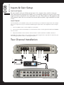
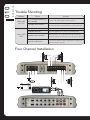
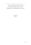
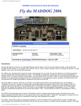
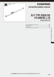
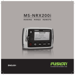
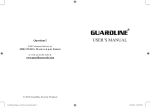
MS - A M50 4
MARINE
A M P L I FI E R
User/Installation Manual
FUSIONENTERTAINMENT.COM
Contents
Feature Overview . . . . . . . . . . . . . . . . . . . . . . . . . . . . . . . . . . . Pg 3
Control Descriptions . . . . . . . . . . . . . . . . . . . . . . . . . . . . . . . . .Pg 4
Installation . . . . . . . . . . . . . . . . . . . . . . . . . . . . . . . . . . . . . . . . .Pg 6
Connections . . . . . . . . . . . . . . . . . . . . . . . . . . . . . . . . . . . . . . . .Pg 6
Inputs and Gain Setup . . . . . . . . . . . . . . . . . . . . . . . . . . . . . . . .Pg 8
Two Channel Installation . . . . . . . . . . . . . . . . . . . . . . . . . . . . . . Pg 8
Three Channel Installation / Power Cable Calculator . . . . . . . . .Pg 9
Four Channel Installation / Trouble Shooting . . . . . . . . . . . . . .Pg 10
Specifications . . . . . . . . . . . . . . . . . . . . . . . . . . . . . . . . . . . . . . Pg 11
RECORD YOUR PRODUCT DETAILS HERE:
MODEL NUMBER
DATE OF PURCHASE
AFFIX RECEIPT HERE
2010 Version 1.0
• Variable Bass Boost 0 - + 18dB
• Variable LP and HP Electronic X-OVER @ 18dB/octave
• 4 Gauge Power and Ground Connections
• Nickel Plated Audio Input and Output RCA Connections
• Nickel Plated RCA Output for multi-amp Installations
2-OHM STABLE STEREO
Provides the option of connecting an extra pair of speakers in parallel, 2
per channel at 2-Ohms (A total of 8 speakers).
MARINE GRADE CONNECTIONS
Nickel plated RCA connectors and stainless components improve signal
flow for optimum output
CLASS-AB DESIGN
The 500 Watt 2-Ohm stable (per channel) design ensures clean and
powerful amplification of the input signal, enough to rock the boat.
CONFORMAL COATED CIRCUITRY
Provides added protection from salt air and moisture to ensure maximum
product life.
MARINE GRADE CHASSIS
Stainless steel end and bottom plates provide a stunning finish coupled
with environmental protection.
RCA LINE OUT
A pass through RCA output enables linking of multiple amplifiers for
enhanced system performance
003
• 2 Ohm Stable MOSFET Amplifier Design
FEATURE OVERVIEW
Feature Overview
CONTROLS
004
Control Descriptions
1
2
3
11 12 13
4
5
14
6
7
8
9
10
15
1 Power And Status LEDs:
This shows if the amplifier has been correctly powered up and if any faults are present.
2 Crossover Selector:
Set the appropriate mode of operation. The 3 positions available are OFF, LP and
HP.
3 Low Pass:
Set the crossover switch 2 to LP when a subwoofer is connected. Ensure the crossover frequency is set at 100Hz or below, this feature is designed to filter all mid to
high frequencies that only FULL RANGE speakers should produce. NOTE: Failure to
do so could result in speaker damage.
4 High Pass:
Set the crossover switch 2 to HP and turn this control to 65Hz or above when using
speakers smaller than 6”, this feature is designed to filter all low bass frequencies
that only SUBWOOFERS should produce. NOTE: Failure to do so could result in
speaker damage.
5 Bass Boost:
This is a variable control to increase the bass boost at 45Hz from 0 -+18dB of gain,
This is a variable control filters out all Sub Bass Frequencies below the set point at
18dB/octave.
7Level:
This allows level adjustment of the input signal. Use this control to correctly match
the head unit to the amplifier. To set this control correctly, turn the amplifier level
to MIN and the head unit to 3/4 volume, with the BASS and TREBLE on zero , then
slowly turn up this amplifier level control towards the MAX end of the control.
NOTE: If the sound becomes distorted, turn this control down.
8 RCA Input (channel 1 & 2):
Connect these RCA connectors to the LOW LEVEL output connection from the head
unit.
9 RCA Input (channel 3 & 4):
Connect these RCA connectors to the LOW LEVEL output connection from the head
unit.
10RCA Output:
Use these RCA Output connectors to connect to a secondary amplifier. This output
is a SUMMED OUTPUT connection derived from the RCA input connectors.
11Ground Connection:
Connect directly to suitable ground point via a 4 gauge power cable. NOTE: This is
to be the first wire to connect. Damage could result if this is not done.
12Remote Connection:
This input is for turning the amplifier on and off. This requires a switched positive
(+12V) to power ‘ON’ the amplifier, this can be found on the rear of the head unit in
the form of an electric antenna output, or a remote on output. If not available you
can wire to a switched +12V supply.
13Power +12V Connection:
This must be connected to the battery positive (+) terminal via a 4 gauge power
cable and with an inline fuse or circuit breaker at the battery end. NOTE: This is to
be the last wire to connect up during installation as damage could result.
14Fuses:
Please ensure the correct type of fuse is fitted, as specified in this manual. PLEASE
NOTE: the MS-AM504 has 2x 25A fuses.
15Speaker Output:
See channel installation diagrams in this manual for correct speaker connection.
CONTROLS
6 Subsonic Filter:
005
adjust to suit.
INSTALLATION
006
Installation
Mounting
Appropriate mounting is very important for the prolonged life expectancy of any
amplifier. Select a location that allows enough space so sufficient airflow is maintainable
and a location that provides protection from moisture. Keep in mind that an amplifier
should never be mounted upside down. Upside down mounting will compromise heat
dissipation through the heatsink and could engage the thermal protection circuit.
Excessive heat will shorten your amplifiers life. To maximise heat dissipation, be sure to
leave at least 2.5” of clearance around the amplifier. If space is of the essense and the
amplifier must be mounted in an enclosed or restricted area, a small 3 inch fan should
be used in correspondence with a duct so the heat can flow past the Heatsink.
To avoid scratching your new FUSION amplifier, pre-drill the mounting holes with either
a 3mm or 9/64” diameter drill bit and use the screws supplied in the accessory kit. Be
sure to investigate your mounting area thoroughly to avoid electrical wires, vacuum lines
or fuel lines.
Installation Options
The quality of installation will affect the performance and reliability of your FUSION
amplifier. For maximum performance we recommend you have your new FUSION
amplifier installed by an authorised FUSION dealer. Our highly skilled dealers have vast
knowledge of our products and their installation techniques are necessary to unleash
the high performance capabilities of your amplifier.
If you decide to connect the amplifier yourself, it is important that you read this manual
carefully and throughout before starting. Once you have finished reading and you still
have questions regarding installation, we recommend your FUSION dealer.
Connection
FUSION amplifiers are designed to work within a 10 to 16 volt DC range. Before
any wires are connected, the vessel’s electrical system should be checked for correct
voltage supply with the help of a voltmeter. First, check the voltage at the battery the
voltmeter should read between 12 and 13.8 Volts. If your vessel’s electrical system is
not up to these specification, we recommend having it checked by an auto electrician
before any further installation. Once the vessel is checked, make certain the correct
cable size is used. We recommend using the following cables calculator diagram on
page 9 to calculate the correct power cable for your application.
Power
FUSION amplifiers should be wired directly to the battery using the appropriate sized
cable. Start at the vessels battery and run the power cable through to the amplifier.
FUSION recommends the use of grommets when passing the power cable through any
metal wall to avoid sharp corners or sharp body parts that may easily cut through the
insulation on the cable.
Avoid running the power cable over engine components. The use of an inline fuse
or circuit breaker is a must, this will prevent the risk of a potential fire caused be a
short in your power cable. Connect the fuse holder or circuit breaker as close to the
Ground
When grounding your FUSION amplifier, use the same gauge cable for ground as
you did for the power. Secure the ground cable to the appropriate ground point, now
its time to connect the power and ground cables to the amplifier. Cut both cables to
length. Use a hex type screwdriver to loosen the +12V and the GND connections on the
amplifier. Terminate the ground first, and then the +12V and please make sure that you
terminate them into the correct terminals. Then tighten the screws down securely.
Speaker Load
Keep in mind FUSION ‘AM’ series amplifiers are high power amplifiers and not high
current amplifiers. In other words they require a minimum impedance of 2 ohms
STEREO and 4 ohms bridged MONO to operate trouble free. Too low of an impedance
could send your FUSION amplifier into protection mode and/or damage the amplifier.
Remote Turn-on
This terminal must be connected to a switched +12V source. Typically, remote
turn-on leads are provided at the head unit which will turn on and off the amplifier. If the
head unit does not have a remote turn-on lead, then a power antenna wire can be used.
If neither of these leads are present on the head unit then a switched +12V supply must
be used , like the ACC +12V.
Run a minimum of 18 gauge wire from the amplifier location to the source of the
switched +12V lead. Connect the source remote output to the wire. Go back to the
amplifier and cut the wire to length. Loosen the screw terminal marked REM on the
amplifier using a hex type screwdriver. Slip the wire into the connector and tighten the
screw securely.
CONNECTION
007
battery positive terminal as possible. Use a fuse or circuit breaker of equal value as that
found on the chassis of your FUSION amplifier. You may now connect the cable to the
battery, but remember to leave the fuse out or circuit breaker off until all other cable
connections are made.
INSTALLATION
008
Inputs & Gain Setup
Low Level Inputs
Be extra careful with your RCA interconnects. Hiss, engine noise, and fan noise can
easily be picked up through RCA cables if run incorrectly. Avoid running your RCAs near
large wire looms and electric fans if possible. Run your RCA cables on the opposite side
of the power cable. Be sure to check for correct balance (Red is right and black or white
is left)
Level Control
On the amplifier, is the LEVEL control, this control allows you to match the input level of the amplifier to the output level of your head unit. Matching the input can be accomplished in three simple
steps:
1. Turn the LEVEL control on the amplifier to minimum.
2. Turn up the head unit and adjust to 2/3 maximum volume ensuring that the BASS and TREBLE
are set to zero.
3. Adjust the LEVEL control until the desired volume is achieved without audible distortion.
Remember, the gain control is not a volume control. Ignoring the three steps above may leave you
with damaged speakers and/or a damaged amplifier.
Two Channel Installation
FUSE
PLEASE NOTE: The crossover selector positions
0-4ft
4-7ft
7-10ft
10-13ft 13-16ft 16-19ft 19-22ft 22-28ft
0-20
14
12
12
10
10
8
8
8
20-35
12
10
8
8
6
6
6
4
35-50
10
8
8
6
4
4
4
4
50-65
8
8
6
4
4
4
4
2
65-85
6
6
4
4
2
2
2
0
85-105
6
6
4
2
2
2
2
0
105-125
4
4
4
2
0
0
0
0
125-150
2
2
2
0
0
0
0
0
The above chart shows cable gauges to be used, if no less than a 0.5 volt drop is acceptable. If aluminium wire or tinned wire is used, the gauges should be of
an even larger size to compensate. Cable gauge size calculation takes into account terminal connection resistance. 1 Metre = 3.28 Feet
Three Channel Installation
L
R
FUSE
FR
RR
FL
RL
FL FR
RL RR
PLEASE NOTE: The crossover selector positions
CONNECTION
Total Amperage
009
Power Cable Calculator
INSTALLATION
010
Trouble Shooting
Problem
Power LED
not ‘ON
Status LED
‘ON’
Cause
Solution
Fuse at battery blown or
not installed
Replace with correct type and rated fuse.
Improper connections
Check that the ground wire, power wire and the
remote wires are connected to the correct terminal
Fuse blown
Replace with correct type and rated fuse.
Amplifier too hot
Move the amplifier into a more ventilated area
Speaker wires shorted
Check that there are no speaker wires shorted to any
other wire and also check if any wire is shorted to ground
Internal malfunction
Disconnect all wires except ground, power and remote.
Then turn the amplifier ’ON’, if the protection light is still
’ON’ then return for service
Four Channel Installation
L
FUSE
R
L
R
FR
RR
FL
RL
FL FR
RL RR
PLEASE NOTE: The crossover selector positions
Specifications
Signal to Noise
>95dB
Separation>60dB
Input Sensitivity
300mV - 8V
LP Variable Crossover
40Hz - 160Hz @ 18dB/octave
HP Variable Crossover
40Hz - 600Hz @ 18dB/octave
Variable Bass Boost
0 - + 18dB @ 45Hz
Variable Subsonic Filter
20Hz - 55Hz @ 18dB/octave
Input Impedance20kΩ
Damping factor>200
T.H.D0.05%
Fuse Ratings
2 x 25A
Dimensions(mm)
229 (W) x 366(L) x 53(H)
12.6 Volt power output specification
50 Watts RMS x 4 @ 4Ω 1% THD+N
75 Watts RMS x 4 @ 2Ω 1% THD+N
150 Watts RMS x 2 @ 4Ω Bridged 1% THD+N
14.4 Volt power output specification
65 Watts RMS x 4 @ 4Ω 1% THD+N
100 Watts RMS x 4 @ 2Ω 1% THD+N
200 Watts RMS x 2 @ 4Ω Bridged 1% THD+N
FUSIONENTERTAINMENT.COM