1
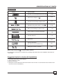
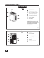
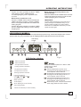
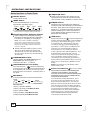
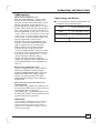
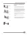
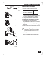
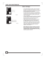
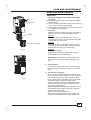
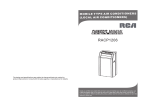
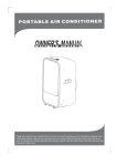
PORTABLE AIR CONDITIONER
OWNER'S MANUAL
Model: MPM3-12HRN1-BH9
Model: MPM3-14CRN1-B I 6
CONTENTS
Environmental concerns......................... .............................................................................................2
SAFETY PRECAUTIONS
Always do this ...................................................................................................................................3
Never do this .....................................................................................................................................3
Electrical information .........................................................................................................................3
IDENTIFICATION OF PARTS
Accessories .......................................................................................................................................4
Names of parts...................................................................................................................................5
OPERATING INSTRUCTIONS
Operation panel of the air conditioner ..............................................................................................6
Operating condition .........................................................................................................................10
INSTALLATION INSTRUCTIONS
Location ...........................................................................................................................................11
Window kit installation .....................................................................................................................11
Exhaust hose installation .................................................................................................................14
Water drainage ................................................................................................................................15
CARE AND MAINTENANCE
Care and maintenance ....................................................................................................................16
TROUBLESHOOTING TIPS
Troubleshooting ...............................................................................................................................17
NOTE
The rating data indicated on the energy label is based
on the testing condition of installing the un-extended
air exhaust duct without adaptor A & B (The duct and
the adaptor A & B are listed in the accessories chart
of the Instruction Manual).
1
2
SAFETY PRECAUTIONS
To prevent injury to the user or other people and property damage, the following instructions must be
followed. Incorrect operation due to ignoring of instructions may cause harm or damage.
!
Always do this
Your air conditioner should be used in such a way
that it is protected from moisture. e.g. condensation,
splashed water, etc. Do not place or store your air
conditioner where it can fall or be pulled into water
or any other liquid. Unplug immediately.
Always transport your air conditioner in a vertical
position and stand on a stable, level surface during
use.
Turn off the product when not in use.
Always contact a qualified person to carry out
repairs. If the supply cord is damaged it must be
repaired by a qualified repairer.
Keep an air path of at least 30cm all around the
unit from walls, furniture and curtains.
If the air conditioner is knocked over during use,
turn off the unit and unplug from the mains supply
immediately.
Never do this
Do not operate your air conditioner in a wet room
such as a bathroom or laundry room.
Do not touch the unit with wet or damp hands or
when barefoot.
Do not press the buttons on the control panel with
anything other than your fingers.
Do not remove any fixed covers. Never use this
appliance if it is not working properly, or if it has
been dropped or damaged.
Never use the plug to start and stop the unit.
Always use the switch on the control panel.
Do not cover or obsturct the inlet or outlet grilles.
Do not use hazardous chemicals to clean or come
into contact with the unit. Do not use the unit in the
presence of inflammable substances or vapour such
as alcohol, insecticides, petrol,etc.
Do not allow children to operate the unit
unsupervised.
Do not use this product for functions other than
those described in this instruction manual.
Energy Save
Use the unit in the recommended room size.
Locate the unit where furniture cannot obstruct the air flow.
Keep blinds/curtains closed during the sunniest part pf the day.
Keep the filters clean.
Keep doors and windows closed to keep cool air in and warm air out.
WARNING
For your safety
Do not store or use gasoline or other flammable vapors and liquids in the vicinity of this or any other
appliance.
Avoid fire hazard or electric shock. Do not use an extension cord or an adaptor plug. Do not remove
any prong from the power cord.
WARNING
Electrical Infor mation
Be sure the electrical service is adequate for the model you have chosen. This information can be found
on the serial plate, which is located on the side of the cabinet and behind the grille.
Be sure the air conditioner is properly grounded. To minimize shock and fire hazards, proper grounding is
important. The power cord is equipped with a three-prong grounding plug for protection against shock
hazards.
Your air conditioner must be used in a properly grounded wall receptacle. If the wall receptacle you intend
to use is not adequately grounded or protected by a time delay fuse or circuit breaker, have a qualified
electrician install the proper receptacle.
Ensure the receptacle is accessible after the unit installation.
3
IDENTIFICATION OF PARTS
Accessories
PARTS :
PARTS NAME :
QUANTITY :
Exhaust hose with adapter B(round mouth)
1 set
Wall Exhaust Adaptor A(
1 pc
)
1 pc
Window Exhaust Adaptor B(flat mouth)
Expansion Plug and wooden screw(
TEMP
FAN
HIGH
MED
LOW
TIMER ON
TIMER OFF
ON/OFF FAN SPEED
ECONOMY
RESET LOCK
FOLLOW
LED
ME
DISPLAY TURBO
SET TEMPERATURE( C)
AUTO
COOL
DRY
HEAT
MODE
ION
SWING
NOTE: Optional parts(
)
4/ pc
Band (For bundling the power cord)
1 pc
Drain Hose(For continuous drainage)
1 pc
Window Slider Kit
1 set
Foam seal
3/pc
Remote Controller
(For remote control models only)
1pc
Battery(For remote controller)
2/pc
), some models without.
Check all the accessories are included in the package and please refer to the installation instructions for
their usage.
Suggested tools for window kit installation
1. Screwdriver(medium size Phillips)
2. Tape measure or ruler
3. Knife or scissors
4. Saw(In the event that the window kit needs to be cut down in size because the window is too
narrow for direct installation)
4
IDENTIFICATION OF PARTS
NAMES OF PARTS
Front
1
1
Operation Panel
2
Horizontal Louver Blade
(Lift it up during operation)
3
Signal receptor(optional)
4
Air intake (Air filter inside)
5
Carrying Handle
(both sides)
2
5
3
4
NOTE: The illustrations are for
explanation purposes only. The
actual shape of the machine you
purchased may be slighted
different. The actual shape
should prevail.
Fig.1
Rear
6
Air intake
7
Power cord outlet
8
Drain Outlet A (Used on
dehumidifying operation)
9
Drain Outlet B (Used on heating
operation)
6
7
10
8
11
9
10
Air Outlet
11
Air intake(Air filter inside)
Fig.2
5
OPERATING INSTRUCTIONS
OPERATION PANEL OF THE AIR CONDITIONER
Before you begin, thoroughly familiarize yourself with the control panel and remote controller
and all its functions, then follow the symbol for the functions you desire.
The unit can be controlled by the unit control panel alone or with the remote controller .
NOTE: This manual does not include Remote Controller Operations, see the <<Remote
Controller Instruction>> packed with the unit for details.
LED DISPLAY MODELS:
NOTE:The following illustration is for explanation purposes only. The actual shape of the control
panel of the unit you purchased may be slightly different. But the function are the same.
5
Mode indicator
lights
4
6
Fan speed
indicator light
SWING
TIMER ON TIMER OFF
AUTO
Follow me
LOW
COOL
DRY
FAN
MODE
TURBO
HEAT
MED
ION/
PLASMA
SLEEP
HI
FOLLOW ME
FAN
11 indicator light
(on some models)
7
2
8
10
9
1
3
Fig.3
1 Power button
Power switch on/off.
2 Mode select button
Selects the appropriate operating
mode. Each time you press the button,
a mode is selected in a sequence that
goes from AUTO, COOL, DRY, FAN and
HEAT(For cooling & heating models only).
The Mode indicator lights illuminate under
the different mode settings Fig.4.
3 Fan speed button
Control the fan speed. Press to select the fan
speed in four steps-LOW, MED, HI or AUTO.
The fan speed indicator light illuminates under
different fan settings except AUTO.
Fan Options:
AUTO (1 speeds) AUTO
COOL (4 speeds) Low-Med-Hi-Auto
DRY(1 speed) LOW
FAN (4 speeds) Low-Med-Hi-Auto
HEAT(4 speeds) Low-Med-Hi-Auto
4 Temperature/Time Up/Down buttons
Used to adjust (increasing/decreasing)
temperature settings(1 C/2 F increments)
in a range of 17 C(62 F) to 30 C(88 F).
NOTE: The control is capable of displaying
temperature in degrees Fahrenheit or degrees
Celsius. To convert from one to the other, press
and hold the Up and Down buttons at the same
time, for 3 seconds.
Under Auto-timer setting, press or hold
the Up or Down button to change the
Auto time by 0.5 hour increments, up to
10 hours, then at one hour increments up
to 24 hours.
5
TIMER button:
Used to initiate the AUTO ON start time/
AUTO OFF stop time program , in
confuction with &
buttons.
6
SWING button:
Allows the top horizontal louver blades to
oscillate forward and backward to the
desired direction. Each press will change
O
the swing angle for 6 . If keeping pressing
the button without releasing for 2 more
seconds, the louver blades would oscillate
forward and backward automatically.
6
OPERATING INSTRUCTIONS
7 TURBO button
Used to set the strong fan speed, the set
temperature will reach in the shortest time.
This function is only availabe on COOL mode.
11 Follow me indicator light
(optional)
This feature can be activated by
the remote control ONLY. The
remote control serves as a remote
thermostat allowing for the precise
temperature control at its location.
To activate the Follow Me feature, point
the remote control towards the unit and
press the Follow Me button. T he remote
display is actual temperature at its
location. The remote control will send
this signal to the air conditioner every 3
minutes interval until press the Follow
Me button again.
If the unit does not receive the Follow
Me signal during any 7 minute interval,
the FOLLOW ME indicator light turns off
to indicate the mode has ended.
8 .ION/PLASMA button(optional)
Press the this button, the anion generator/
Plasma Filter is energized and will help to
remove pollen and impurities from the air,
and trap them in the filter.
9 SLEEP button
Press this button, the selected temperature
will increase(cooling) or decrease(heating)
O
O
by 1 C/2 F 30 minutes.The temperature will
then increase(cooling) or decrease(heating)
O
O
by another 1 C/2 F after an additional 30
minutes. This new temperature will be
maintained for 7 hours before it returns
to the originally selected temperature. This
ends the Sleep mode and the unit will
continue to operate as originally programmed. The Sleep mode program can be
cancelled at any time during operation by
again pressing the SLEEP button,or turning
off the unit, or pressing the MODE or FAN
button.
NOTE: This feature is unavailabe under
FAN or DRY mode.
10 LED Display
Shows the set temperature in " C " or " F "
and the Auto-timer settings.
Error codes:
E1- Room temperature sensor errorUnplug the unit and plug it back in. If
error repeats, call for service.
E2- Evaporator temperature sensor errorUnplug the unit and plug it back in. If
error repeats, call for service.
E3- Conenser temperature sensor errorUnplug the unit and plug it back in. If
error repeats, call for service.
P1- Bottom tray is full - Remove the bottom
drain plug and drain off the water.
7
TIMER operation
When the air conditioner is on:
Press the "TIMER " button will first activate
the Timer Off setting program. The TIMER
OFF indicator light illuminates and the
LED display window appears "0.0 " .
- Continue pressing or keep pressing the
"UP or DOWN " button to select the time
you need the unit to stop operation. If
press UP button, the time is programmed
as :0.0- 0.5-1.0-1.5-2.0-2.5-3.0-3.5-4.0-4.5
-5.0- 5.5-6.0-6.5-7.0-7.5-8.0-8.5-9.0-9.510-11-12-13-14-15-16-17-18-19-20-21-22
-23-24-0.0. If press the DOWN button, the
time is programmed in reverse order.
- When the desired time is established,
wait for 5 seconds or press the TIMER
button again to register the time. The
setting temperature will immediately
revert back in the display window. And
the TIMER OFF indicator light remains
on indicating the program is set.
- If press the TIMER button once again,
the TIMER ON indicator light illuminates
and the LED display window appears
"0.0 ". You are ready to adjust the ON
Timer setting.
-
OPERATING INSTRUCTIONS
-
-
-
Perform the same operations as above TIMER
OFF setting to set the TIMER ON time.
The starting/stopping time is adjustable from
0.0 to 24.
When the air conditioner is off:
Press the "TIMER" button will first activate the
TIMER ON setting program. Press the TIMER
button once again will activate the TIMER OFF
setting program.
Perform the same operations as above TIMER
ON and TIMER OFF setting to set the starting/
stopping time.
When both start and stop time are set
simultaneously:
- Both the TIMER ON and TIMER OFF indicator
lights illuminate and remain on until the auto
starting/stopping time is achieved.
IMPORTANT:
The time will be registered in 5 seconds period
(after pressing the UP/DOWN button), so you
should continue pressing the button until the
desired time is established. Otherwise you must
repeat the steps again.
LCD DISPLAY MODELS:
NOTE:The following illustration is for explanation purposes only. The actual shape of the control
panel of the unit you purchased may be slightly different. But the function are the same.
LCD display
window
2
ON
OFF
MODE
FAN
6
TURBO
SLEEP
7
1
ON/OFF
auto
UP
SWING
8
10
9
LCD display window :
ON
OFF
auto
Timer on indicator
Timer off indicator
Auto operation indicator
Cooling operation indicator
Dry operation indicator
Fan operation indicator
Heating operation indicator
Fan speed indicator
(Low( )--Med( )--Hi(
Auto (No display ))
)--
Sleep operation
Turbo display
Anion display(on some models)
DOWN
3
TIMER
ON/OFF
4
ION/
PLASMA
5
Fig.4
Display
Shows the set temperature in " C " or " F "
and the error codes.
Error codes:
- Room temperature sensor errorUnplug the unit and plug it back in. If
error repeats, call for service.
- Evaporator temperature sensor errorUnplug the unit and plug it back in. If
error repeats, call for service.
- Conenser temperature sensor errorUnplug the unit and plug it back in. If
error repeats, call for service.
- Bottom tray is full - Remove the bottom
drain plug and drain off the water.
Auto swing display
Follow me indicator(on some models)
8
OPERATING INSTRUCTIONS
Button functions on Control Panel
1 ON/OFF button
Power switch on/off.
2 MODE button
Press the MODE button to select the
appropriate operating mode:
AUTO COOL
DRY FAN
HEAT
auto
HEAT mode is for cooling & heating models only.
3 Temperature/Time Up/Down buttons
Used to adjust (increasing/decreasing)
temperature settings(1 C/2 F increments)
in a range of 17 C(62 F) to 30 C(88 F).
NOTE: The control is capable of displaying
temperature in degrees Fahrenheit or degrees
Celsius. To convert from one to the other, press
and hold the Up and Down buttons at the same
time, for 3 seconds.
Under Auto-timer setting, press or hold
the Up or Down button to change the
Auto time by 0.5 hour increments, up to
10 hours, then at one hour increments up
to 24 hours.
4 TIMERON/OFF button:
Used to initiate the AUTO ON start time/
AUTO OFF stop time program , in
confuction with &
buttons.
5 ION/PLASAM button(on some models)
Press this button,
indicator displayed
indicating the anion generator/Plasma filter
is energized and will help to remove pollen
and impurities from the air, and trap them in
the filter.
6 FAN button
Press the FAN button to select the desired fan
speed:
LOW
MED
HI
AUTO
(No display)
Fan Options:
AUTO (1 speeds) AUTO
COOL (4 speeds) Low-Med-Hi-Auto
DRY(1 speed) LOW
FAN (4 speeds) Low-Med-Hi-Auto
HEAT(4 speeds) Low-Med-Hi-Auto
9
7 TURBO/PUMP button
Used to set the strong fan speed, the set
temperature will reach in the shortest time.
This function is only availabe on COOL mode.
8 SWING button:
Allows the top horizontal louver blades to
oscillate forward and backward to the desired
direction. Each press will change the swing
O
angle for 6 . If keeping pressing the button
without releasing for 2 more seconds, the
louver blades would oscillate forward and
backward automatically.
9 SLEEP button
Press this button, the
indicator displayed
and the selected temperature will increase
O
O
(cooling) or decrease(heating) by 1 C/2 F
in 30 minutes.The temperature will then
increase(cooling) or decrease(heating)
O
O
by another 1 C/2 F after an additional 30
minutes. This new temperature will be
maintained for 7 hours before it returns
to the originally selected temperature. This
ends the Sleep mode and the unit will
continue to operate as originally programmed. The Sleep mode program can be
cancelled at any time during operation by
again pressing the SLEEP button,or turning
off the unit, or pressing the MODE or FAN
button.
NOTE: This feature is unavailabe under
FAN or DRY mode.
10 Follow me indicator( )(on some models)
This feature can be activated by the
remote control ONLY. The remote
control serves as a remote thermostat
allowing for the precise temperature
control at its location.
To activate the Follow Me feature, point
the remote control towards the unit and
press the Follow Me button. T he remote
display is actual temperature at its location.
The remote control will send this signal to
the air conditioner every 3 minutes interval
until press the Follow Me button again.
If the unit does not receive the Follow Me
signal during any 7 minute interval, the
FOLLOW ME indicator disappeared to
indicate the mode has ended.
OPERATING INSTRUCTIONS
TIMER operation
-
-
-
-
-
-
-
-
When the air conditioner is on:
Press the "TIMER ON/OFF " button will first
activate the Timer Off setting program. The
word OFF and the clock symbol begin to flash
and the LCD display window appears "0.0 " .
Continue pressing or keep pressing the "UP or
DOWN " button to select the time you need the
unit to stop operation. If press UP button, the
time is programmed as :0.0- 0.5-1.0-1.5-2.0-2.5
-3.0-3.5-4.0-4.5 -5.0- 5.5-6.0-6.5-7.0-7.5-8.0-8.5
-9.0-9.5-10-11-12-13-14-15-16-17-18-19-20-21
-22-23-24-0.0. If press the DOWN button, the
time is programmed in reverse order.
When the desired time is established, wait 5
seconds or press the TIMER ON/OFF button
again to register the time. The word OFF
flashes and the clock symbol illuminates ,
indicating the OFF timer has been set.
If press the TIMER ON/OFF button once again,
the word ON and clock symbol flash and the
LCD display window appears "0.0 ". You are
ready to adjust the ON Timer setting.
Perform the same operations as above
TIMER OFF setting to set the TIMER ON time.
The starting/stopping time is adjustable from
0.0 to 24.
Operating condition
The air conditioner must be operated within the
temperature range indicated below:
MODE
ROOM TEMPERATURE
COOL
17 C ~35 C/62 F~ 95 F
Dehumidification
HEAT
O
O
O
O
O
O
O
O
13 C ~35 C/54 F~ 95 F
O
O
O
O
5 C ~30 C/41 F~ 88 F
When the air conditioner is off:
Press the "TIMER ON/OFF" button will first
activate the TIMER ON setting program.
Press the TIMER ON/OFF button again will
activate the TIMER OFF setting program.
Perform the same operations as above
TIMER ON/OFF setting to set the starting/
stopping time.
When both start and stop time are set
simultaneously:
If the TIMER ON TIMER OFF feature is set,
the word ON flashes, the word OFF and clock
symbol illuminate and remain on.
If the TIMER OFF TIMER ON feature is set,
the word OFF flashes, the word ON and clock
symbol illuminate and remain on.
IMPORTANT:
The time will be registered in 5 seconds period
(after pressing the UP/DOWN button), so you
should continue pressing the button until the
desired time is established. Otherwise you must
repeat the steps again.
10
INSTALLATION INSTRUCTIONS
INSTALLATION INSTRUCTIONS
Location
30c
m
30
cm
Fig.5
Horizontal
window
The air conditioner should be placed on a firm
foundation to minimize noise and virbration. For
safe and secure positioning, place the unit on a
smooth, level floor strong enough to support the unit.
The unit has casters to aid placement, but it should
only be rolled on smooth, flat surfaces. Use caution
when rolling on carpet surfaces. Do not attempt to
roll the unit over objects.
The unit must be placed within reach of a properly
rated grounded socket.
Never place any obstacles around the air inlet or
outlet of the unit.
Allow at least 30cm of space from the wall for
efficient air-conditioning.
Window kit Installation
Window Slider Kit
Minimum:67.5cm(2.22ft).
Maxmum:123cm(4.04ft).
Fig.6
Your window kit has been designed to fit most standard
"Vertical" and "horizontal"window applications,
However, it may be necessary for you to improvise/
modify some aspects of the installation procedures for
certain types of window. Please refer to Fig. 6& Fig.7 for
minimum and maximum window openings.
Note: If the window opening is less than the mentioned
minimum length of the window slider kit, cut that one
with holes in it short to fit for the window opening. Do
never cut out the hole in window slider kit.
Horizontal
window
Window Slider Kit
Minimum:67.5cm(2.22ft).
Maxmum:123cm(4.04ft).
Fig.7
11
INSTALLATION INSTRUCTIONS
Installation in a double-hung sash
windows
Foam seal A
(adhesive type)
1. Cut the foam seal(adhesive type) to the proper
length and attach it to the window stool. Fig.8
Fig.8
Window kit
2. Attach the window slider kit to the window stool.
Adjust the length of the window slider kit according
to the width of window, short the adjustable window
kit if the width of window is less than 27 inches.
Open the window sash and place the window slider
kit on the window stool. Fig.9
3. Cut the foam seal(adhesive type) to the proper
length and attach it on the top of the window. Show
as in Fig.10.
26.5 ~ 48
Window stool
Fig.9
4. Close the window sash securely against the
window.
Window kit
5. Cut the foam seal to an appropriate length and
sealing the open gap between the top window sash
and outer window sash. Show as in Fig.11.
Window stool
Fig.10
Foam seal
Fig.11
12
INSTALLATION INSTRUCTIONS
Installation in a sliding sash
windows
Foam seal A
(adhesive type)
1. Cut the foam seal(adhesive type) to the proper
length and attach it to the window frame,Fig.12.
Fig.12
Window
panel
2. Attach the window slider kit to the window stool.
Adjust the length of the window slider kit according
to the width of window, short the adjustable window
kit if the width of window is less than 27 inches.
Open the window sash and place the window slider
kit on the window stool. See Fig.13.
26.5 ~ 48
3. Cut the foam seal(adhesive type) to the proper
length and attach it on the top of the window.
Show as in Fig.14.
Fig.13
4. Close the sliding sash securely against the window.
5. Cut the foam seal to an appropriate length and
sealing the open gap between the top window sash
and outer window sash. Show as in Fig.15.
Fig.14
Foam seal
Fig.15
13
INSTALLATION INSTRUCTIONS
Adaptor B
Adaptor B
Exhaust hose installation:
The exhaust hose and adaptor must be installed or
removed in accordance with the usage mode.
Fig.16
COOL mode
Install
FAN, HEAT or DEHUMIDIIFY
mode
Remove
1. Install the window Exhaust adaptor B(flat mouth)
onto the exhaust hose as shown in Fig.16. Refer to
the previous pages for window kit installation.
2. Install the flexible Exhaust hose as depicted
in Fig.17 & 18.
Fig.17
Fig.18
The exhaust hose can be installed into the wall .
(Not applicable to the units without adaptor A,
expansion plugs and wooden screws of Accessories ).
1. Prepare a hole in the wall. Install the wall Exhaust
adaptor A onto the wall(outside) by using 4 expansion
plugs and wooden screws, be sure to fix thoroughly.
(See Fig.19)
2. Attach the Exhaust hose to wall Exhaust adaptor A.
Note:
Cover the hole using the adaptor cap when not in
use.
Expansion plug
position
Adaptor A
Adaptor
cap
The duct can be compressed or extended
moderately according to the installation
requirement, but it is desirable to keep the
duct length to a minimum.
max 120CM
min 30CM
IMPORTANT:
DO NOT OVER BEND THE DUCT (SEE Fig.20)
Fig.19
Fig.20
14
CARE AND MAINTENANCE
Water drainage:
Drain outlet A
Drain outlet B
-
Fig.21
-
Attach a section of
drain hose onto the
connector inside.
Fig.22
During Dehumidifying modes, remove the drain
plug A from the back of the unit(Fig.21), install
the drain connector(5/8 universal female mender)
with 3 4 hose(locally purchased).
During Heating mode, remove the drain plug B
from the back of the unit(Fig.21), install the drain
connector (5/8 universal female mender) with 3/4
hose(locally purchased). Make sure the drain
outlet A is plugged.
For the models without drain connector, just attach
the drain hose to the hole. Place the open end of
the hose directly over the drain area in your
basement floor. Please refer to Fig.22.
When the water level of the bottom tray reaches
a predetermined level, the unit beeps 8 times,
the digital display area shows "P1" and the unit
stop operation. Carefully move the unit to a drain
location, remove the bottom drain plug and let the
water drain away(Fig.24). Restart the machine
until the "P1" symbol disappears. If the error
repeats, call for service.
NOTE: When the relative humidity is less than
80%, the water drainage is not needed during
cooling operation. If performing above water
drainage during cooling operation, the cooling
efficiency will be reduced.
15
CARE AND MAINTENANCE
CARE AND MAINTENANCE
IMPORTANT:
1) Be sure to unplug the unit before cleaning or
servicing.
2) Do not use gasoline, thinner or other chemicals to
clean the unit.
3) Do not wash the unit directly under a tap or using a
hose. It may cause electrical danger.
4) If the power cord is damaged, it should be repaired
by manufacture or its agency.
Filter tap
1. Air filter
Air filter
-
Air intake grille
Fig.23
-
-
Clean the air filter at least once every two weeks to
prevent inferior fan operation because of dust.
Removal
,,
,,
,,
,,
Grasp the filter tab, pull the filter out then up .
Then remove the screw on the side air intake grille,
pull the filter out. See Fig.23.
Cleaning
Wash the air filter by immersing it gently in warm
O
O
water(about 40 C/104 F) with a neutral detergent.
Rinse the filter and dry it in a shady place.
Mounting
Replace the air filters.
Replacement air filter are available through the
Customer Service Parts Department.
CAUTION: Never operate the unit without the air
filter in place as this may result in damage to the
unit.
2. Unit enclosure
-
Fig.24
Use a lint-free cloth soaked with neutral detergent
to clean the unit enclosure. Finished by a dry clean
cloth.
3. Unit idle for a long time
- When you plan to leave this unit unused for a long
time, remove the bottom rubber plug from the back
hole and attach a section of the continuous drain
hose . All the water in the bottom tray would drain
outside through the drain hose.(See Fig.24)
- Keep the appliance running on FAN mode for half
a day in a warm room to dry the appliance inside
and prevent mold forming.
- Stop the appliance and unplug it, wrapped the cord
and bundle it with the tape. Remove the batteries
from the remote controller.
- Clean the air filter and reinstall it.
- Disconnect the exhaust hose, keep it safety, and
cover the window(wall) hole with the adaptor cap.
16
TROUBLESHOOTING TIPS
TROUBLE SHOOTING
TROUBLES
POSSIBLE CAUSES
SUGGEST REMEDIES
1. Unit does not
- Water full indicator blinks, water tank
Dump the water in the water tank.
Start when
is full.
Pressing on/off
- Room temperature is higher than
Button
the set temperature.(Heating mode)
- Room temperature is lower than
Reset the temperature.
Reset the temperature.
the set temperature.(Cooling mode)
- The windows or doors in the room
are not closed.
- There are heat sources inside the
2. Not cool enough
Make sure all the windows and
doors are closed.
Remove the heat sources if possible.
room.
- Exhaust air duct is not connected or
blocked.
3. Power shut off at
Heating mode
4. Noisy or vibration
sure it can function properly.
- Temperature setting is too high.
Decrease the set temperature.
- Air filter is blocked by dust.
Clean the air filter.
- The automatic over heat protection
function. When the temperature at
O
O
the air outlet exceed 70 C/158 F,
the device will stop.
Switch on again after the unit
- The ground is not level or not flat
Place the unit on a flat, level
enough.
5. Gurgling sound
Connect the duct and make
- The sound comes from the flowing
has cool down.
ground if possible.
It is normal.
of the refrigerant inside the
air-conditioner.
6. Compressor does not work
- The bottom tray is full
and the digital display area
shows
¡°P1¡±
Rremove the bottom plug and drain
the collected water away. If it does
not work after restart, contact the
service people.
7. The cooling indicator light
flashes at 1Hz and the digital
display area shows
¡°E1¡±
8. The FAN indicator light
flashes at 1Hz and the digital
display area shows
¡°E2¡±
9. The Dehumidifying indicator
light flashes at 1Hz and the
digital display area shows
E3
¡° ¡±
17
- The room temperature Sensor is
Contact service people
off or short-circuit.
- The Evaporator Temperature Sensor
is off or short-circuit.
- The Condenser Temperature Sensor
is off or short-circuit.
Contact service people
Contact service people