1
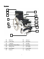
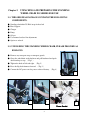
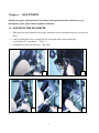
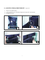
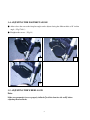
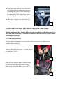
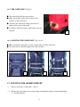
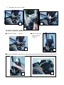
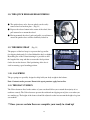
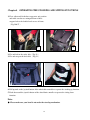
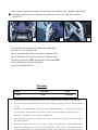
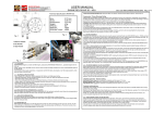
INSTRUCTION MANUAL
STANDING WHEELCHAIR
KARMAN HEALTHCARE INC.
City of Industry, CA 91748
www.KarmanHealthcare.com
**Karman Healthcare Inc. Recommends Patient Seek Physicians Counsel Before Purchase
TABLE OF CONTENTS
P.3 XO-101: Parts Explanation
Chapter 1. SAFETY TIPS
1-1. Standing
1-2. Wheel locks
1-3. Rear wheels
1-4. Armrests
1-5. Power drive Attachments
1-6. Modifications
Chapter 2.
UNPACKING AND PREPARING THE STAND UP
WHEELCHAIR XO SERIES STAND UP WHEELCHAIR FOR USE
2-1. The original package and accessories.
2-2. Unfolding the stand up wheelchair
Chapter 3. ADJUSTMENT
3-1. Adjusting the seat depth
3-2. Adjusting the backrest height
3-3. Adjusting the Footrest height
3-4. Adjusting the Footrest Angle
3-5. Adjusting the wheel Lock
3-6. The knee support and safety belt and chest belt
3-7. Adjusting the Armrest height
3-8. The rear wheels
3-9. The heel strap
3-10. Gas spring
3-11. The seat cushion
Chapter 4. OPERATION OF STANDING AND SITTING
Chapter 5. CONTROL SYSTEM
5-1. Battery and control box
5-2. Battery charge
Chapter 6. MAINTENANCE & WARRANTY
1
XO Series
1
8
2
3
9
10
4
11
5
12
6
13
14
7
01
Back-rest
08
Arm-rest
02
Chest Strap
09
Side Panel
03
Controller
10
Seat Belt
04
Hand Rim & Rear Wheel
11
Leg Straps
05
Wheel Lock
12
Gas Spring
06
Anti-Tippers
13
Control Box
07
Footrest
14
Heel Strap
2
Chapter 1. SAFETY TIPS
1-1. STANDING
Attention:
:
●Before using the standing wheelchair you should be familiar with the operation and the functions of
the XO units’ parts.
●When using the standing function, use only in standard household and/or hard even ground
conditions. Not use when ground is wet or slippery.
●In case of staircase, the standing wheelchair must be carried by 2 persons on the left and right hand
side not in-front and behind.
●When the user leaves the standing wheelchair, he/she should not use their feet to push of from the
footplate, to avoid the dangers.
Warning: Maximum weight limit should not exceed
Any XO Unit - 250 lbs
1-1.1. Standing up stresses your body in ways you may not be used to. Therefore we recommend
you consult your doctor or physical therapist before using the stand-up wheelchair.
1-1.2. Before standing up it is absolutely vital that the knee support, safety belt and chest belt
are fixed correctly.
1-2. WHEELS & LOCKS
Wheel locks are not designed to slow the wheelchair down when it is moving. Wheel locks hold the
wheelchair in place when it is at a complete stop. Always set both wheel locks when entering or
stand-up or leaving the wheelchair.
3
1-3. REAR WHEEL
1-3.1. QUICK RELEASE AXLES
Make sure the wheels axle is all the way through before mounting the XO unit. If the release
button is inside the frame, the wheels will release and the user will be in danger.
1-3.2. PNEUMATIC TIRES
Check pneumatic tires weekly for proper inflation level, listed on tire sidewall.
1-3-3. CURBS, INCLINES AND RAMPS
Always practice with a healthcare professional or attendant.
Before attempting to negotiate curbs, inclines or ramps alone.
It is important for you to develop a safe technique that is suitable to your abilities.
WARNING:
Doing a ”wheelie” (tilting the wheelchair backward to its balance point) can be dangerous and it
is not recommended you perform this maneuver under any circumstances.
1-4. ARMRESTS
Flip-back Armrests
Never lift the wheelchair by the armrests. These parts are detachable and lifting the
wheelchair by them may cause damage to the chair or injury to the user.
1-5. POWER DRIVE ATTACHMENTS
Karman Healthcare Inc. standing wheelchair does not advocate the use of power drive attachments on
any XO series wheelchair. Use of a power drive attachment on a XO series wheelchair alters its
intended use. Installation of a power drive attachment is considered an alteration to the frame and
voids the warranty.
1-6. MODIFICATIONS
Making any unauthorized modifications or using parts not supplied by Karman Healthcare Inc., or any
change to the wheelchair structure might make it an unsafe and will void the warranty.
4
Chapter 2. UNPACKING AND PREPARING THE STANDING
WHEELCHAIR XO SERIES FOR USE
2-1. THE ORIGINAL PACKAGE CONTAINS THE FOLLOWING
COMPONENTS.
●
●
●
●
●
●
●
Standing wheelchair W/ Heel strap & chest belt
Knee Support
Charger
Pump
Oil pot
User manual and tool for adjustments
Option as ordered
2-2. UNFOLDING THE STANDING WHEELCHAIR, PLEASE PROCEED AS
FOLLOWS:
● Remove any transport straps or transport guards.
● Grasp the wheelchair at the backrest and pull backward and push
downward up to stop. (Fig-1)
● Tighten the knob of left and right. (Fig-2)
● Press the flip-back Armrest forward. (Fig-3)
● Connect the DC power cord to power socket of battery. (Fig-4)
1
3
2
4
Power Socket
5
Chapter 3. ADJUSTMENT
Should you require adjustments and alterations to the mechanism of the wheelchair, or any
maintenance work, please contact qualified technicians.
3-1. ADJUSTING THE SEAT DEPTH
(1)Pull upward or push forward on the handle controller, let the wheelchair frame rise over the rear
wheel.
(2)After loosening the screws on both sides the seat depth can be adjusted using the
various holes at 1” increments. (Fig-5~7)
(3)Retighten the screws on both sides.(Fig-8&9)
5
6
7
8
6
9
3-2. ADJUSTING THE BACKREST HEIGHT (Fig-10~13)
(1) Remove the padded backrest.
(2) After opening the screws, the backrest height can be adjusted in 2 cm increments.
(3) Retighten the screws.
11
10
13
12
7
3-3. ADJUSTING THE FOOTREST HEIGHT
The height of the footrest is adjustable and should be altered in line with your body proportions to
guarantee the best standing position possible. Footrest adjustment should also take account of your
choice of seat cushion. (Fig-14~16)
14
15
16
● After loosening the screws the footrest height can be adjusted using the various holes at ~3/4”
increments.
● Retighten the screws.
8
3-4. ADJUSTING THE FOOTREST ANGLE
● After release the screws the footplate angle can be adjusted using the different hole at 10° incline
angle.(Fig-17&18)
● Retighten the screws.(Fig-19)
17
18
19
3-5. ADJUSTING THE WHEEL LOCK
Note:
Make sure pneumatic tires are properly inflated(
(level listed on tire side wall)
)before
adjusting the wheel locks.
9
● Loosen the socket head cap screw on the top
of the clamp. Slide the mounting bar forward
or backward and rotate it to the correct angle
position. The knurl should be embed into the
tire approximately 5/16” when in the locked
position.(Fig-20)
● Make sure to retighten the socket head cap
screw.
20
3-6. THE KNEE SUPPORT AND SAFETY BELT AND CHEST BELT
The most important safety features of the stand-up wheelchairs are the knee support &
safety belt and chest belt. It is absolutely essential that these be correctly in place before
you attempt to stand up.
3-6-1. THE KNEE SUPPORT
The knee support holds the knees in an extended posture and prevents you slipping out the
wheelchair while standing up.
Attach the two triangular form of the knee lock
support to the double-head screws on either side of
the wheelchair.(Fig-21)
21
Center the knee support in front of each knee using
the Velcro fasteners, then pull it until it is sitting
firmly in place, just below the knee cap.(Fig-22)
22
10
3-6-2. THE SAFETY BELT(Fig-23)
● The safety belt holds the waist in place.
● Make sure that the safety belt is secure on the
backrest of Velcro fasteners.
● To release the safety belt. Simply press the red
button in the center of the catch.
● To slacken, hold the catch at a right angle to the belt
and pull.
23
3-6-3. ADJUSTING THE CHEST BELT(Fig-24~26)
● Make sure that the chest belt is secure on the backrest of Velcro fasteners.
● The chest belt is to hold the upper body (chest) in place.
25
24
26
3-7. ADJUSTING THE ARMREST HEIGHT
(1) Release the knobs(left& right)
(Fig-27)
(2) Release the left & right screws on the clamp, adjusting the clamp to suit position(height
7”~10”)(Fig-28&29)
11
(3) Retighten the screws of clamp.
27
29
28
FOLDING THE BACKREST
● Release the knobs. (Fig-30)
● Pull the flip-back
armrest upward
(Fig-31)
30
31
●Grasp the wheelchair at the backrest and pull upward and then push forward up to stop(Fig-32&33)
33
32
12
3-8. THE QUICK RELEASE REAR WHEELS
● The quick-release axles, the rear wheels can be easily
removed and set back on place(Fig-34)
● Depress the release button in the center of the wheel, then
pull outward or re-mount the wheel.
● Having mounted the wheel, push and pull it several times to
ensure the quick-release axle has definitely locked in.
34
3-9. THE HEEL STRAP (Fig-35)
The purpose of the heel strap is to prevent the legs and/or
feet slipping backwards. It is fitted behind the heels or higher.
By making use of the Velour fastening it is possible to alter
the length of the strap and thus to ensure the ideal position
for the feet on the footrest. Ideal positioning of the feet is
vital in ensuring a good standing position.
35
3-10. GAS SPRING
The gas springs are specially designed to help hold your body weight in the balance.
Note: Contents under pressure. Do not take apart puncture apply heat or fire.
3-11. THE SEAT CUSHION
The Velcro fasteners fitted to the surface of your seat should allow you to attach the majority of set
cushions securely. The Velcro fasteners prevent the cushion from slipping out of place even when you
are standing up. The height of the footrest should be adjusted to take into account the height of a given
seat cushion.
**Once you are certain these are complete your ready to stand up!
13
Chapter4. OPERATING THE STANDING AND SITTING FUNCTIONS
1. First, adjust and fix the knee support to suit position
and make sure the two triangular form of knee
support lock to the double-head screws of frame.
(Fig-36&37)
36
37
2. Fix and lock in the safety belt.(Fig-38)
3. Fix and strap on the chest belt.(Fig-39)
38
39
4. Pull upward on the joystick button of the wheelchair controller to operate the standing up function.
5. Push downward the joystick button of the wheelchair controller to operate the sitting down
function.
Note:
● Please make sure your hand is not under the stand up mechanism.
14
Chapter 5. CONTROL SYSTEM
5-1. BATTERY AND CONTROL BOX CONNECTION
The main electrical control system is composed of motor, control box, battery and controller.
Connect the power cord of control box to the battery. (Fig-40&41)
Battery Capacity Indictor
41
40
5-2. BATTERY CHARGE (Fig-42)
1. First, connect the battery charge cords to the battery DC power socket and make sure the cord is
securely connected.
2. Connect the AC power cord to the AC socket.(100~240V)
3. Make sure to fully charge your battery every time, not charging it completely will cause the
lifespan of this battery to diminish faster.
Battery capacity
indictor color
Power condition
Green
Full power
Yellow
Low power
Red
Empty power
The buzzers for Battery Capacity & Controller
Battery
15
42
power
indicator
color
Green
Battery
Capacity
Full power
Full power
Controller
Switch ON
Switch OFF
Sound of buzzer
Sound short 1 times
Sound short 1 times
(Not using over 30 min)
Low power
Low power
Yellow
Red
◎Switch ON
◎ Switch OFF
Sound short 1 times
Sound short 1 times
(Not using over 30 min)
Empty power ◎Control mode
Sound short continue for control
◎Switch can only Push
time
downward (Safety mode)
Empty power Shut down
Sound long 1 time and
(Must charge immediately) continuous sound short 5 times
Note:
:
If the energy indicator is yellow consider charging the battery immediately. If for any reason
you happen to be standing up without any power left, charge for approximately 5 minutes to
be able to operate the sit down function.
Attention:
1. Battery can complete ~250 cycles (depending on weight and condition of the
battery)
2. New battery must be charged over 8 hours.
3. Used battery must be charged up to 8 hours (depending on use)
4. Charge your battery from the battery charger provided by manufacturer only.
Chapter 6. MAINTENANCE
● When cleaning your XO series use a dry or slightly moistened cloth to wipe the wheelchair down.
For stubborn or oily stains, apply a mild detergent to the cloth. Do not hose down your XO series
with water.
● According to frequency of use, check tire pressure between once a week and once a month. If
necessary, pump up the tires in line with manufacturer’s recommendations.
● Check the state of the tread on the tires every one to six months. If a tire is heavily or unevenly
worn, it should be replaced.
● Every one to six months, check that the brakes still work smoothly. Having applied the brakes, the
16
wheels should stop turning completely. If the brakes are ineffective, they should be tightened up.
● According to frequency of use, lubricate the joint between one a week and once a month.
(Fig-43~45)
43
44
45
-Lower
limbs
joint contracture (absolute
contra-indication)
******
WARNING******
This
chair is not intended for those who have:
-Instability on lower extremity joints
-Severe abnormal reflex (Lower extremities withdraw reflex)
-Severe abnormal reflex (Lower extremities withdraw reflex)
-Total hip replacement (THR) and total knee replacement(TKR)
-Severe osteoporosis on lower extremities
-Severe postural hypotension
Warranty
Frame
3 Years
Electrical
1 Year
Parts
6 Months
1.
Structural frame components including platform, fork, seat post and frame welds are warranted, to the original owner
2.
To present a claim, Customer shall deliver the defective part for exchange or repair if possible to an Authorized Karman
provider.
3.
This warranty is for the replacement or repair, at the option of Karman Healthcare Inc., of defective parts only and does
not cover any labor charges including, but not limited to, charges incurred for installation of replacement parts or
additional fees, which may be imposed by Karman Healthcare Inc.
4.
All warranty replacement parts are under warranty from the date of purchase of the original “product” and not from the
date of part replacement.
17
5.
This warranty is valid and enforceable only on “products” purchased in the United States and from a Karman provider.
6.
This warranty is applicable only to the customer as an original purchaser of the “product” from an Authorized Karman