1
HD Video/Audio Decoder
User Manual
UD.6L0203D1128A01
User Manual of DS-6400HDI-T Decoder
User Manual©2015 Hangzhou Hikvision Digital Technology Co., Ltd.
This user manual is intended for users of Decoder (“Product”). It includes instructions on how to use the Product.
The software embodied in the Product is governed by the user license agreement covering that Product.
About this Manual
This Manual is subject to domestic and international copyright protection. Hangzhou Hikvision Digital
Technology Co., Ltd. (“Hikvision”) reserves all rights to this manual. This manual cannot be reproduced,
changed, translated, or distributed, partially or wholly, by any means, without the prior written permission of
Hikvision.
Trademarks
and other Hikvision marks are the property of Hikvision and are registered trademarks or
the subject of applications for the same by Hikvision and/or its affiliates. Other trademarks mentioned in this
manual are the properties of their respective owners. No right of license is given to use such trademarks without
express permission.
Disclaimer
TO THE MAXIMUM EXTENT PERMITTED BY APPLICABLE LAW, HIKVISION MAKES NO
WARRANTIES, EXPRESS OR IMPLIED, INCLUDING WITHOUT LIMITATION THE IMPLIED
WARRANTIES OF MERCHANTABILITY AND FITNESS FOR A PARTICULAR PURPOSE, REGARDING
THIS MANUAL. HIKVISION DOES NOT WARRANT, GUARANTEE, OR MAKE ANY
REPRESENTATIONS REGARDING THE USE OF THE MANUAL, OR THE CORRECTNESS, ACCURACY,
OR RELIABILITY OF INFORMATION CONTAINED HEREIN. YOUR USE OF THIS MANUAL AND ANY
RELIANCE ON THIS MANUAL SHALL BE WHOLLY AT YOUR OWN RISK AND RESPONSIBILITY.
TO THE MAXIMUM EXTENT PERMITTED BY APPLICABLE LAW, IN NO EVENT WILL HIKVISION,
ITS DIRECTORS, OFFICERS, EMPLOYEES, OR AGENTS BE LIABLE TO YOU FOR ANY SPECIAL,
CONSEQUENTIAL, INCIDENTAL, OR INDIRECT DAMAGES, INCLUDING, AMONG OTHERS,
DAMAGES FOR LOSS OF BUSINESS PROFITS, BUSINESS INTERRUPTION, SECURITY BREACHES,
OR LOSS OF DATA OR DOCUMENTATION, IN CONNECTION WITH THE USE OF OR RELIANCE ON
THIS MANUAL, EVEN IF HIKVISION HAS BEEN ADVISED OF THE POSSIBILITY OF SUCH
DAMAGES.
SOME JURISDICTIONS DO NOT ALLOW THE EXCLUSION OR LIMITATION OF LIABILITY OR
CERTAIN DAMAGES, SO SOME OR ALL OF THE ABOVE EXCLUSIONS OR LIMITATIONS MAY NOT
APPLY TO YOU.
Privacy Notice
Surveillance laws vary by jurisdiction. Check all relevant laws in your jurisdiction before using this product for
surveillance purposes to ensure that your use of this product conforms.
Support
Should you have any questions, please do not hesitate to contact your local dealer.
1
User Manual of DS-6400HDI-T Decoder
Regulatory information
FCC information
FCC compliance: This equipment has been tested and found to comply with the limits for a digital device,
pursuant to part 15 of the FCC Rules. These limits are designed to provide reasonable protection against harmful
interference when the equipment is operated in a commercial environment. This equipment generates, uses, and
can radiate radio frequency energy and, if not installed and used in accordance with the instruction manual, may
cause harmful interference to radio communications. Operation of this equipment in a residential area is likely to
cause harmful interference in which case the user will be required to correct the interference at his own expense.
FCC conditions
This device complies with part 15 of the FCC Rules. Operation is subject to the following two conditions:
1. This device may not cause harmful interference.
2. This device must accept any interference received, including interference that may cause undesired operation.
EU Conformity Statement
This product and - if applicable - the supplied accessories too are marked with "CE" and comply therefore with
the applicable harmonized European standards listed under the Low Voltage Directive 2006/95/EC, the EMC
Directive 2004/108/EC, the RoHS Directive 2011/65/EU.
2012/19/EU (WEEE directive): Products marked with this symbol cannot be disposed of as unsorted municipal
waste in the European Union. For proper recycling, return this product to your local supplier upon the purchase of
equivalent new equipment, or dispose of it at designated collection points. For more information see:
www.recyclethis.info.
2006/66/EC (battery directive): This product contains a battery that cannot be disposed of as unsorted municipal
waste in the European Union. See the product documentation for specific battery information. The battery is
marked with this symbol, which may include lettering to indicate cadmium (Cd), lead (Pb), or mercury (Hg). For
proper recycling, return the battery to your supplier or to a designated collection point. For more information see:
www.recyclethis.info.
2
User Manual of DS-6400HDI-T Decoder
Preventive and Cautionary Tips
Before connecting and operating your device, please be advised of the following tips:
•
•
•
•
•
Ensure unit is installed in a well-ventilated, dust-free environment.
Unit is designed for indoor use only.
Keep all liquids away from the device.
Ensure environmental conditions meet factory specifications.
Ensure unit is properly secured to a rack or shelf. Major shocks or jolts to the unit as a result of dropping it
may cause damage to the sensitive electronics within the unit.
• Use the device in conjunction with an UPS if possible.
• Power down the unit before connecting and disconnecting accessories and peripherals.
• Improper use or replacement of the battery may result in hazard of explosion. Replace with the same or
equivalent type only. Dispose of used batteries according to the instructions provided by the battery
manufacturer.
CHANGE THE DEFAULT PASSWORD
The default password (12345) for the Admin account is for first-time
log-in purposes only. You must change this default password to better protect against security risks, such
as the unauthorized access by others to the product that may prevent the product from functioning properly
and/or lead to other undesirable consequences.
For your privacy, we strongly recommend changing the password to something of your own choosing
(using a minimum of 8 characters, including upper case letters, lower case letters, numbers, and special
characters) in order to increase the security of your product.
Proper configuration of all passwords and other security settings is the responsibility of the installer and/or
end-user.
3
User Manual of DS-6400HDI-T Decoder
Table of Contents
CHAPTER 1 Introduction ........................................................................................................ 6
1.1 Description ...................................................................................................................... 7
1.2 Features ........................................................................................................................... 7
CHAPTER 2 Panels and Connections ...................................................................................... 9
2.1 Front Panel .................................................................................................................... 10
2.2 Rear Panel...................................................................................................................... 10
CHAPTER 3 Initial Network Parameters Configuration ....................................................... 12
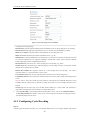
3.1 Searching Active Devices Online ................................................................................ 13
3.2 Modifying Network Parameters ................................................................................... 14
CHAPTER 4 Decoder Configuration and Operation by Web Browser .................................. 15
4.1 Decoding Operation....................................................................................................... 17
4.1.1 Configuring Decoded Video Display ..................................................................... 17
4.1.2 Configuring Dynamic Decoding ............................................................................ 18
4.1.3 Configuring Cycle Decoding .................................................................................. 20
4.1.4 Configuring Video Wall Display ............................................................................ 22
4.1.5 Enabling/Disabling the Decoding Channel ............................................................ 23
4.1.6 Configuring Picture Overlay .................................................................................. 24
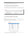
4.1.7 Checking the Connection Status ............................................................................. 24
4.1.8 Checking the Decoding Channel Status ................................................................. 25
4.1.9 Checking the Display Channel Status .................................................................... 25
4.1.10 Configuring Transparent Channel ........................................................................ 26
4.2 Decoder Configuration .................................................................................................. 27
4.2.1 Checking Device Information ................................................................................ 27
4.2.2 Configuring Time Settings ..................................................................................... 27
4.2.3 Configuring Basic Network Settings ...................................................................... 28
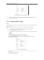
4.2.4 Configuring DDNS Settings ................................................................................... 29
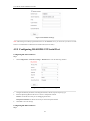
4.2.5 Configuring RS-485/RS-232 Serial Port ................................................................ 31
4.2.6 Configuring Alarm Input / Output Settings ............................................................ 32
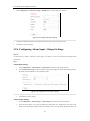
4.2.7 Configuring Arming Time ...................................................................................... 33
4
User Manual of DS-6400HDI-T Decoder
4.2.8 Managing User Account ......................................................................................... 33
4.2.9 Importing/Exporting Parameters ............................................................................ 34
4.3 Configuring Remote Playback ...................................................................................... 36
4.3.1 Normal Playback .................................................................................................... 36
4.3.2 VCA Playback ........................................................................................................ 38
4.4 Switching Working Mode ............................................................................................. 39
4.5 Rebooting, Upgrading and Restoring the Default Settings for the Decoder ................. 40
CHAPTER 5 Decoder Configuration and Operation by Client Software ............................... 42
5.1 Adding an Encoding/Decoding Device ......................................................................... 43
5.2 Setting Video Wall Layout ............................................................................................ 45
5.3 Multi-screen Display ..................................................................................................... 46
5.4 Displaying Video on Video Wall .................................................................................. 47
5.4.1 Decoding and Displaying Video............................................................................. 48
5.4.3 Configuring Playback ............................................................................................. 50
5.5 Configuring VCA .......................................................................................................... 50
5.5.1 Allocating VCA Resource ...................................................................................... 51
5.5.2 Shield Region Configuration .................................................................................. 51
5.5.3 VCA Rule Configuration ........................................................................................ 52
5.5.4 VCA Alarm Configuration ..................................................................................... 54
5.5.6 Viewing VCA Alarm Pictures ................................................................................ 55
CHAPTER 6 Appendix ........................................................................................................... 56
Appendix A. Specifications ................................................................................................. 57
Appendix B. FAQ................................................................................................................ 60
Appendix C. List of Third-party IP Cameras Access .......................................................... 61
5
User Manual of DS-6400HDI-T Decoder
CHAPTER 1
Introduction
6
User Manual of DS-6400HDI-T Decoder
1.1 Description
Designed for the high-definition video monitoring system, DS-6400HDI-T Series HD Video/Audio Decoder is
developed on the basis of TI platform, Linux operating system and Netra processor, ensuring high reliability and
stability of system running.
DS-6400HDI-T Series HD Video/Audio Decoder is capable of decoding video at 8MP resolution and outputting
decoded video via BNC, VGA, DVI or HDMI interfaces, and it also supports multiple network protocols and
multiple stream transmission mode. The decoded video can be displayed on video wall or large screen.
1.2 Features
Decoding Video and Audio
Private H.264, standard H.264, MPEG2 and MPEG4 video stream formats are supported.
Support PS, RTP and private customized data encapsulation formats.
PAL and NTSC image standards supported.
DS-6401HDI-T provides the HDMI/VGA/BNC video output, and other models provide DVI/VGA/BNC video
output.
Decode video stream at resolution of 8MP, 5MP, 3MP, 1080P, 720P, SVGA, VGA, 4CIF, DCIF, 2CIF, CIF and
QCIF.
G.722, G.711A, G.711U, MPEG2-L2 and ACC audio stream formats are supported.
Support of getting stream and decoding by channel zero, stream ID, HiDDNS and VGA/DVI local channel (not
supported by DS-6401HDI-T only).
Support of getting stream and decoding by URL method.
High-definition video output via DVI/VGA/HDMI connector and standard-definition video output via BNC
connector.
Window jointing for video wall display.
Decoding Capacity
Refer to the following table for the decoding capacity and display modes of different models in normal decoding
mode:
Resolution
Resolution
Model
8MP
5MP
1080P
720P
DS-6401HDI-T
DS-6404HDI-T
1-ch
2-ch
2-ch
4-ch
4-ch
8-ch
DS-6408HDI-T
4-ch
8-ch
DS-6410HDI-T
5-ch
DS-6412HDI-T
6-ch
DS-6416HDI-T
8-ch
4CIF
Windowdivision Mode
Multi-display
Mode
8-ch
16-ch
16-ch
32-ch
1/4/6/8/9/12/16
1/4/6/8/9/12/16
-1×2, 1×3, 1×4, 2×1, 2×2
16-ch
32-ch
64-ch
1/4/6/8/9/12/16
10-ch
20-ch
40-ch
80-ch
1/4/6/8/9/12/16
12-ch
24-ch
48-ch
90-ch
1/4/6/8/9/12/16
1×2, 1×3, 1×4, 2×1, 2×2,
2×3, 2×4, 2×5, 3×2, 3×3,
4×2, 5×2, 3×4, 4×3
1/4/6/8/9/12/16
1×2, 1×3, 1×4, 2×1, 2×2,
2×3, 2×4, 2×5, 3×2, 3×3,
4×2, 5×2, 3×4, 4×3, 5×3,
3×5, 4×4
16-ch
32-ch
64-ch
100-ch
7
1×2, 1×3, 1×4, 2×1, 2×2,
2×3, 3×2, 2×4, 4×2
1×2, 1×3, 1×4, 2×1, 2×2,
2×3, 2×4, 2×5, 3×2, 3×3,
4×2, 5×2
User Manual of DS-6400HDI-T Decoder
Decoding Mode
Dynamic decoding: Log on the remote encoder or remote stream media server to select a channel of video
source to acquire video stream, and then decode and output the video for local display.
Cycle decoding: Set multiple remote monitoring channels on a decoding channel, and the decoder is capable
of performing cycle decoding according to the configured sequence and time. The stream sources can be
obtained via remote access to the encoder or stream media server and decoded for local output. A maximum of
64 channels are allowed for cycle decoding.
Obtain stream from stream media server: The decoder can receive real-time data by access to stream
media server, and then decode the video stream and output them on the video wall. The private RTSP is adopted
as the control protocol, and the TCP/UDP is used for receiving the data stream.
Remote playback of record files: By remote access to the encoding devices with storage capability, and
directly obtain the record files from the encoder, and finally decode for local output.
Network
One 10/100/1000Mbps self-adaptive Ethernet interface.
Support TCP, UDP and Multicast network protocols.
Multiple DDNS settings: Peanut Hull, Dyndns, IPServer, NO-IP and HiDDNS.
Support SADP software to automatically search and discover the online devices in local network area.
Automatically get IP address by DHCP protocol.
Remote upgrading and maintenance can be done via web browser or client software.
User Administration
A maximum of 32 user accounts can be created by the system, including 1 administrator and 31 normal users.
The user name of the administrator is admin, which cannot be modified, and the password is allowable to be
modified by the administrator only; no deletion of the administrator is allowed, and the administrator is
authorized to set the operation permissions for other users.
Transparent Channel
The decoder adopts the RS-232/RS-485 serial interface to realize transparent transmission, and the transparent
channel of the decoder supports multicast transparent transmission as well. Multiple transparent channels can be
established simultaneously.
Two-way Audio
The decoder is capable of realizing two-way audio with the remote client.
8
User Manual of DS-6400HDI-T Decoder
CHAPTER 2
Panels and Connections
9
User Manual of DS-6400HDI-T Decoder
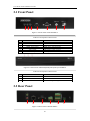
2.1 Front Panel
1
2
3
4
5
6
7
Figure 2.1 Front Panel of DS-6401HDI-T
Table 2.1 Description of Front Panel
1
2
3
4
5
6
7
LED Indicator & Interface
Connections
POWER
LINK
Tx/Rx
HDMI Video Output
VGA Video Output
Audio Output
Video Output
Power LED indicator
Network connection LED indicator
Data transmitting/receiving status LED indicator
HDMI output of decoded video
VGA output of decoded video
Audio output, 3.5mm connector
Video output, BNC connector
Figure 2.2 Front Panel of DS-6404/6408/6410/6412/6416HDI-T
Table 2.2 Description of Front Panel
LED Indicator & Interface
1
2
POWER
LINK
3
Tx/Rx
Connections
Power LED indicator
Network connection LED indicator
Data transmitting/receiving status LED indicator
2.2 Rear Panel
1
2
3
4
5
Figure 2.3 Rear Panel of DS-6401HDI-T
10
6
User Manual of DS-6400HDI-T Decoder
Table 2.3 Description of DS-6401HDI-T Rear Panel
Interface
LINE IN/OUT
LAN
RS-232 Serial Interface
RS-485 Serial Interface
Alarm In
Alarm Out
Power Supply
1
2
3
4
5
6
Connections
Two-way audio input/output, 3.5mm connector.
10/100/1000 Mbps Ethernet interface
Connect to RS-232 devices, e.g., PC, etc.
Connect to RS-485 devices, e.g., keyboard, etc.
4 alarm inputs
4 alarm outputs
12 VDC power input
Rear Panel of DS-6416HDI-T
4
1
3 5
2
7
6
9
8
10
12
13
11
Figure 2.4 Rear Panel of DS-6416HDI-T
Note: For DS-6404/6408/6410/6412HDI-T models, 4/8/10/12 DVI-I video output connectors are provides on the
rear panel.
Table 2.4 Description of DS-6416HDI-T Rear Panel
Interface
Connections
VGA Video Input
VGA video input
DVI-I Video Input
DVI-I video input ( support DVI-to-VGA adapter)
2
DVI-I Video Output
DVI output of decoded video
3
LINE IN/OUT
4
AUDIO OUT
5
LAN
6
USB Interface
7
RS-232 Serial Interface
1
8
9
10
VIDEO OUT
RS-485 Serial Interface
Two-way audio input/output, 3.5mm connector.
DB15 connector for audio out, connecting to audio output device with the
DB15-to-BNC adapter.
10/100/1000 Mbps Ethernet interface
Reserved
Connect to RS-232 devices, e.g., PC, etc.
DB15 connector for video output, connecting to video output device (e.g.,
monitor) with the DB15-to-BNC adapter.
Connect to RS-485 devices, e.g., keyboard, etc.
Alarm In
4 alarm inputs
Alarm Out
4 alarm outputs
11
GND
Grounding
12
Power Supply
Power input interface
13
Power Switch
Power On/Off Switch
11
User Manual of DS-6400HDI-T Decoder
CHAPTER 3
Initial Network Parameters
Configuration
12
User Manual of DS-6400HDI-T Decoder
Purpose:
If you don’t know the IP address of the decoder and this is not the first time you use the decoder, you can use
SADP (IP finder) software or the Serial port tools to find out the IP address of the decoder and to configure the IP
address or other network parameters of it. It is recommended to change the default IP address for the first time to
use it.
This chapter aims to tell the procedures of using the SADP software to find and configure the IP address and other
parameters of the device.
Note:
For the first-time user, the default user name of DS-6400HDI-T is admin, and the default IP address is 192.0.0.64.
It is highly recommended to change the default user name and password after initial use.
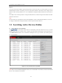
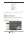
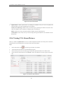
3.1 Searching Active Devices Online
Click
Search online devices automatically
to run the SADP software and it will automatically search the online devices every 15 seconds
from the subnet where your computer locates. It displays the total number and information of the searched devices
in the Online Devices interface. Device information including the device type, IP address, port number, gateway,
etc. will be displayed.
Figure 3.1 Search Online Device by SADP
Note: Device can be searched and displayed in the list in 15 seconds after it went online; it will be removed from
the list in 45 seconds after it went offline.
13
User Manual of DS-6400HDI-T Decoder
Search online devices manually
You can also click
to the list.
Note: You can click
to refresh the online device list manually. The newly searched devices will be added
or
on each column heading to order the information; you can click
device table and hide the network parameter panel on the right side, or click
to expand the
to show the network parameter
panel.
3.2
Modifying Network Parameters
Steps:
1.
Select the device to be modified in the device list and the network parameters of the device will be displayed
in the Modify Network Parameters panel on the right side.
2.
Edit the modifiable network parameters, e.g., IP address, port number and gateway.
3.
Enter the password of the admin account of the device in the Password field and click
changes.
Figure 3.2 Add Searched Online Device
14
to save the
User Manual of DS-6400HDI-T Decoder
CHAPTER 4
Decoder Configuration and Operation by
Web Browser
15
User Manual of DS-6400HDI-T Decoder
Purpose:
Since there is no local operation GUI provided for the decoder, you can manage and configure it by web browser
or the iVMS-4200 client software. In this chapter, the operation and management of the decoder by the web
browser is provided.
Note: The tested Web browsers include: IE7 and IE8, chrome, safari and firefox4.
Open the Web browser and input the IP address of Decoder (e.g., http://192.168.0.0) to enter the login page:
Figure 4.1 Login Interface
Enter the user name and password of the device in the dialog box and then click Login to log into the system. By
default, the user name for login is admin and the password is 12345.
The default password (12345) for the Admin account is for first-time log-in purposes only. You
must change this default password to better protect against security risks, such as the unauthorized
access by others to the product that may prevent the product from functioning properly and/or lead
to other undesirable consequences.
The main interface of the control panel of the decoder is showed after successful login.
Figure 4.2 Enter WEB Page of Decoder
16
User Manual of DS-6400HDI-T Decoder
4.1 Decoding Operation
4.1.1 Configuring Decoded Video Display
Purpose:
To realize the display of the decoded video on the video wall, you must set the decoding operation parameters.
Before you start:
Check the cabling of the decoder, and ensure that the decoder is connected to the video wall or monitor via the
video output interfaces.
To set the video output of the decoder, the first step is to choose the video output interfaces.
Steps:
1.
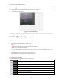
Click Decode Operation > Decode Mode > Display Control to enter the display control interface:
For the DS-6401HDI-T models, the VGA, BNC and HDMI video output interfaces are provided; and for DS6404/6408/6410/6412/6416HDI-T, the DVI-I, VGA and BNC video output interfaces are provided.
Figure 4.3 Display Configuration
2.
In the display control interface, you can configure the Display Channel, Video Format (BNC), BNC Output
Scaling (BNC), Output Resolution (VGA, HDMI, DVI) and Display Mode.
Figure 4.4 Configure Display Parameters
3.
Select the window-division display mode. The DS-6400HDI-T series supports 1/4/6/8/9/12/16-division
display mode.
4.
Select the decoding channel from the drop-down list for each sub-window.
5.
Click Save to save the settings.
After having configured the window-division display, the sub-window information can be viewed on the interface.
Note: You can click the
button to enlarge the selected sub-window in full screen mode.
17
User Manual of DS-6400HDI-T Decoder
4.1.2 Configuring Dynamic Decoding
After you have configured the decoded video display mode, you can enable the dynamic decoding now.
Dynamic decoding means that you decode one channel for one decoding window.
Steps:
1.
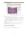
Click Decode Operation > Decode Mode > Dynamic Decoding to enter the dynamic decode settings
interface.
2.
Select a decoding channel from the drop-down list which has been configured for the sub-window in Display
Control Configuration interface.
3.
Configure the dynamic decoding mode for the selected channel.
Three decoding modes are selectable: IP Mode, URL Mode and DDNS Mode.
Task1: Set Encoding Device by IP Mode
Figure 4.5 Set Encoding Device by IP Mode
Configure the following settings:
Manufacturer: Select the Manufacturer of encoding device connected to be decoded. Encoding devices
from the following manufactures are supported: PRIVATE, PANASONIC, SONY, AXIS, SANYO,
BOSCH, ZAVIO, ARECONT, PELCO, SAMSUNG and ONVIF.
Remote Host Address: Enter the IP address of the encoding device to be decoded.
Remote Host Port: Enter the port of the encoding device to be decoded.
Channel Type: Select the channel type of the encoding device for decoding. Four types are selectable:
normal, channel-zero, stream ID and local channel.
Normal: Get the stream from the encoding device by IP address.
Channel-zero: Get the stream from encoding device (DVR) by channel-zero.
Stream ID: Get the stream from the device (transcoder) which supports access by stream ID.
Local Channel: Get the stream by local video input (DVI and VGA) for DS-6410/6412/6416HDI-T series.
18
User Manual of DS-6400HDI-T Decoder
Figure 4.6 Set Channel Type
Remote Host Channel No.: Enter the channel No. of the encoding device for decoding.
User Name/Password: Enter the user name and password used for login to the encoding device.
Transmission Protocol: Select the network transmission protocol to TCP, UDP or Mcast. The
default
protocol is TCP.
Stream Type: Set the stream type to be decoded and the default type is main stream. The sub-stream is
supported for decoding when the encoding device supports dual-stream.
Enable Stream Media Server (optional): Enable the stream media server if required.
Stream Media Server IP Address: Enter the IP address of the server.
Stream Media Server Port: Enter the port No. of the server and the default port is 554.
Stream Media Server Protocol: Select the protocol of the server and the default protocol is TCP.
Task 2: Set Encoding Device by URL Mode
Figure 4.7 Set Encoding Device by URL Mode
URL format:
rtsp://{normal rtsp url}{? username=xxxxx?password=xxxxx? linkmode=xxx},
normal rtsp url: enter the normal RTSP URL format, e.g., 172.6.24.66:554/h264/ch1/main/av_stream.
?username: Enter the user name of the encoding device. Max. length: 32 bytes.
?password: Enter the password used for login to the encoding device. Max. length: 16 bytes.
?linkmode: Set the protocol to TCP or UDP which is case-insensitive.
Example:
rtsp://172.6.24.66:554/h264/ch1/main/av_stream?username=admin?password=12345?linkmode=udp
Notes:
1) When the stream media server is used, the stream media information must be added, e.g.,
rtsp://172.6.22.125:554/hikvision://172.6.22.144:8000:2:0?username=admin?password=12345?linkmode=TC
P.
2) The length of URL should be less than 240 bytes.
3) The URL mode can only be activated when using with the SMS 4.0 or above version of iVMS-4200 client
software.
Task 3: Set Encoding Device by DDNS Mode
19
User Manual of DS-6400HDI-T Decoder
Figure 4.8 Set Encoding Device by DDNS
Configure the following settings:
Domain Name: Input the registered domain name of the DDNS server for the encoding device for decoding.
Domain Name Server Type: Select the DDNS server type. Currently only the HiDDNS is available.
DDNS Server Address: Input the address of the DDNS server (www.hik-online.com).
DDNS Server Port: Input the port number of the DDNS server (e.g., 80).
Manufacturer: Select the Manufacturer of encoding device connected to be decoded. Encoding devices from
the following manufactures are supported: PRIVATE, PANASONIC, SONY, AXIS, SANYO, BOSCH,
ZAVIO, ARECONT, PELCO, SAMSUNG and ONVIF.
Remote Host Port: Enter the port No. of the encoding device for decoding (e.g., 8000).
Channel Type: Select the channel type of the encoding device for decoding. Four types are selectable: normal,
channel-zero, stream ID and local channel.
Remote Host Channel No.: Input the channel No. of the encoding device for decoding. The value 0
represents channel 1, 1 represents channel 2, and so forth.
User Name/Password: Enter the user name and password used for login to the encoding device.
Transmission Protocol: Select the network transmission protocol to TCP, UDP or Mcast. The default protocol
is TCP.
Note: In order to ensure the normal login and operation of the decoder, the bandwidth should not exceed
128Mbps when the UDP protocol is selected for getting stream and not exceed 160Mbps when the TCP is
adopted.
Stream Type: Set the stream type to be decoded and the default type is main stream. The sub-stream is
supported for decoding when the encoding device supports dual-stream.
4.
Click Start Decoding to start decoding, and the decoding status can be viewed in the Connection Status or
the Decoding Channel status interface. And you can view the image from the remote encoding device that is
decoded and displayed on the screen.
4.1.3 Configuring Cycle Decoding
Purpose:
Comparing with the dynamic decoding, the cycle decoding means that you can configure multiple input streams
20
User Manual of DS-6400HDI-T Decoder
(the remote encoding devices) to one output (the channel displayed on the screen).
Steps:
1.
Click Decode Operation > Decode Mode > Cycle Decoding to enter the Cycle Decoding interface.
2.
Select a decoding channel from the drop-down list which has been configured for the sub-window in Display
Control Configuration interface.
3.
Enter the Cycle Time (1~1000 sec).
The cycle time refers to the time duration for decoding each input signal to the defined channel and
displaying on the screen.
Figure 4.9 Configure Cycle Decoding
4.
In the list of IP Mode/URL Mode/DDNS Mode, select an item and click Edit to enter the following interface
to add a new input stream for decoding or edit the existed input stream by IP mode, URL mode or DDNS
mode.
Note: Refer to Chapter 4.1.2 for configuring the input stream assigned to the cycle decoding channel by IP
mode, URL mode or DDNS mode.
Figure 4.10 Edit Cycle Decoding of a Channel
21
User Manual of DS-6400HDI-T Decoder
5.
Click OK to save the settings and back to the Cycle Decoding interface, or click Back to back to the Cycle
Decoding interface without saving.
6.
Repeat Step4 and Step5 to edit other input streams for cycle decoding.
You can also click Delete to remove the configured input stream from the list.
Note: Up to 64 input streams can be configured for each cycle decoding channel.
Figure 4.11 Configure Input Streams for Decoding
7.
Click Save to save the configuration of input streams for the cycle decoding.
Example:
Configuration: Decoding Channel: Channel 1, Cycle Time: 10 seconds, input streams configured for decoding:
10.
Result: the video streams from these 10 input channels will be decoded by decoding channel 1 and displayed on
the screen in sequence with the duration of 10 seconds for each.
4.1.4 Configuring Video Wall Display
The DS-6404/6408/6410/6412/6416HDI-T supports the configuration for the multi-screen video wall display of
the decoded video.
Steps:
1.
Click Decode Operation > Video Wall to enter the following interface:
Figure 4.12 Configure Video Wall
2.
Select the Screen No. from the drop-down list.
3.
Select the Screen Jointing Mode. Different modes are selectable based on models:
DS-6404HDI-T: 1×2, 1×3, 1×4, 2×1, 2×2.
22
User Manual of DS-6400HDI-T Decoder
DS-6408HDI-T: 1×2, 1×3, 1×4, 2×1, 2×2, 2×3, 3×2, 2×4, 4×2.
DS-6410HDI-T: 1×2, 1×3, 1×4, 2×1, 2×2, 2×3, 2×4, 2×5, 3×2, 3×3, 4×2, 5×2.
DS-6412HDI-T: 1×2, 1×3, 1×4, 2×1, 2×2, 2×3, 2×4, 2×5, 3×2, 3×3, 4×2, 5×2, 3×4, 4×3.
DS-6416HDI-T: 1×2, 1×3, 1×4, 2×1, 2×2, 2×3, 2×4, 2×5, 3×2, 3×3, 4×2, 5×2, 3×4, 4×3, 5×3, 3×5, 4×4.
4.
Select the Related Decoding Channel for the selected video wall.
5.
Set the Output Resolution.
Note: You can select the NOT_AVAILABLE option in the Output Resolution to clear the current video wall
configuration.
6.
In the Video Output Configuration area, select the Display Channel for each screen.
7.
Click Save to save the settings.
Notes:
The BNC video output does not support large screen display currently.
It is recommended to configure the display channels with the same video output type for each large
screen, e.g., VGA1, VGA2, VGA3…; or HDMI1, HDMI2, HDMI3….
The display sequence of sub-screens in different screen modes (with DS-6404/6408HDI-T for example) is
shown below:
Figure 4.13 Multi-screen Video Wall Display
4.1.5 Enabling/Disabling the Decoding Channel
Purpose:
The Channel On/Off function enables you to start or stop the decoding and displaying for certain channels.
Steps:
1.
Click Decode Operation > Decode Control > Channel On/Off to enter the following interface:
Figure 4.14 Configure Channel On/Off
23
User Manual of DS-6400HDI-T Decoder
2.
Select a decode channel in the drop-down list in the Decode Channel field.
3.
Set the decoding channel to On or Off.
4.
Click Save to save the settings.
4.1.6 Configuring Picture Overlay
Purpose:
The Picture Overlay function can overlay a picture on the screen for the selected decode channel, and the position
of the picture overlaid on the screen can also be set here.
Steps:
1.
Click Decode Operation > Decode Control > Picture Overlay to enter the following interface:
Figure 4.15 Configure Picture Overlay
2.
Select the decode channel in the drop-down list in the Decoding Channel No. field.
3.
Click Browse to choose a picture from the local directory, and then upload it by clicking the Upload
button.
4.
Set the X coordinate and the Y coordinate of the picture displayed on the screen to move the picture up
and down and left and right.
Note: The picture must be in 24-bit BMP format and its width and height must be 32X pixel, with up to 128×128
resolution and 24 bits depth.
5.
You can check the checkbox of Flash to set the display style of the picture.
6.
Set the picture to show or hide.
7.
Click Save to save the settings.
4.1.7 Checking the Connection Status
Purpose:
The connection status shows the status of the decoding status and the network connection status of the decoding
channel.
Click Decode Operation > Decoding Status > Connection Status to view the connection status of the current
decoding channel in IP mode, URL mode or DDNS mode.
24
User Manual of DS-6400HDI-T Decoder
You can view the status of the network connection displayed on the interface.
Note: The connection status of device will be refreshed regularly.
4.1.8 Checking the Decoding Channel Status
Click Decode Operation > Decoding Status > Decoding Channel to view the status information of the current
decoding channel, including the channel No., decoding status, encoding type, etc. Refer to the following interface:
Figure 4.16 Check Decoding Channel Status
4.1.9 Checking the Display Channel Status
Purpose:
The display channel status interface shows the video output status of the decoder, including the status for the VGA
output, BNC output, HDMI output, and the sub-window information.
Click Decode Operation > Decoding Status > Display Channel to view the working status of the display
channel.
Figure 4.17 Check Display Channel Status
Note: The Display Channel Status of device will be refreshed regularly.
25
User Manual of DS-6400HDI-T Decoder
4.1.10 Configuring Transparent Channel
The Transparent Channel refers to the transmission channel used for forwarding data between the Decoder and the
Encoder without operating on the data transferred.
Steps:
1.
Click Decode Operation > Transparent Channel to enter the Transparent Channel settings interface.
2.
Click to select a transparent channel from the list to configure.
Figure 4.18 Configure Transparent Channel
3.
Select the Local Serial Port and the Remote Serial Port to RS-485 or RS-232.
Local Serial Port: the serial port used as the transparent channel by the decoder.
Remote Serial Port: the serial port used as the transparent channel by the encoding device.
Note: When the RS-232 port is used as the Local Serial Port, you must select the operating mode to Transparent
Channel by entering the Configuration > Serial Port Settings > RS-232 Port interface.
4.
Enter the device information in the Remote Host IP Address, Remote Host Port, and the login User Name and
Password of the encoding device.
Figure 4.19 Check Connecting Status of Transparent Channel
Note: Up to 64 encoding devices are allowed to establish transparent channel transmission with a decoder.
5.
Click Edit to finish the settings.
6.
Click Refresh and the status in the Connection Status will be displayed if the connection is successful.
26
User Manual of DS-6400HDI-T Decoder
4.2 Decoder Configuration
4.2.1 Checking Device Information
Purpose:
You can check the information of the device in the device information interface, such as the Device Type, Device
Serial No., Firmware Version, etc.
Steps:
Click Configuration > Device Information to view the device information, including the Device Type, Device
Serial No., Firmware Version, DSP Version, etc.
Note: The device name can be edited.
Figure 4.20 Check Device Information
4.2.2 Configuring Time Settings
You can set the time for the decoder in the Time Settings interface.
Steps:
1.
Click Configuration > Time Settings to enter the following interface:
Figure 4.21 Configure Time Settings
2.
Configure the time synchronization by NTP server or by manually.
27
User Manual of DS-6400HDI-T Decoder
Configuring Time Sync by NTP Server
A Network Time Protocol (NTP) Server can be configured on your device to ensure the accuracy of system
date/time.
If the device is connected to a Dynamic Host Configuration Protocol (DHCP) network that has time server
properties configured, the camera will synchronize automatically with the time server.
Enable the NTP function by checking the checkbox, and configure the following settings:
NTP Server: IP address of NTP server.
NTP Port: Port of NTP server.
Figure 4.22 Configure Time by NTP
Note: If the device is connected to a public network, you should use a NTP server that has a time synchronization
function, such as the server at the National Time Center (IP Address: 210.72.145.44). If the device is set up in a
more customized network, NTP software can be used to establish a NTP server used for time synchronization.
Configuring Time Synchronization by Manually
Enable the Manual Correction function and then click the
icon to set the system time from the pop-up
calendar.
Figure 4.23 Configure Time by Manually
3.
Select the time zone that is closest to the device’s location from the drop-down list.
4.
Click Save to save the settings.
4.2.3 Configuring Basic Network Settings
Purpose:
You can set the network parameters for the decoder in the parameter configure interface.
Steps:
1.
Click Configuration > Network Settings > General to enter the general network settings interface.
28
User Manual of DS-6400HDI-T Decoder
Figure 4.24 Configure Basic Network Settings
2.
Set the network parameters, including the IP Address, Subnet Mask, Gateway and DNS Server.
3.
Click Save to save the settings.
4.2.4 Configuring DDNS Settings
Purpose:
If your device is set to use PPPoE as its default network connection, you may set Dynamic DNS (DDNS) to be
used for network access.
Prior registration with your DDNS Provider is required before configuring the system to use DDNS.
Steps:
1.
Click Configuration > Network Settings > DDNS to enter the DDNS Settings interface:
2.
Check the Enable DDNS checkbox to enable this feature.
3.
Select DDNS Type. Four different DDNS types are selectable: IPServer, DynDNS, PeanutHull and
HiDDNS.
• DynDNS:
(1)
(2)
(3)
(4)
Enter Server Address for DynDNS (e.g., members.dyndns.org).
Enter the User Name and Password registered in the DynDNS website.
In the Device Domain Name text field, enter the domain obtained from the DynDNS website.
Click Save to save the settings.
Figure 4.25 DynDNS Settings
• IPServer:
(1) Enter Server Address for IPServer.
(2) Click Save to save the settings.
29
User Manual of DS-6400HDI-T Decoder
Note: For the IP Server, You have to apply a static IP, subnet mask, gateway and primary DNS from the ISP.
The Server Address should be entered with the static IP address of the PC that runs IPServer software.
Figure 4.26 IPServer Settings
• PeanutHull:
(1) Enter User Name and Password obtained from the PeanutHull website.
(2) Click Save to save the settings.
Figure 4.27 PeanutHull Settings
• HiDDNS:
(1) Enter the Server Address of the HiDDNS server: www.hik-online.com.
(2) Enter the Domain Name of the device. You can register the alias of the device domain name in the
HiDDNS server first and then enter the alias to the domain name in the decoder; you can also enter
the domain name directly on the decoder to create a new one.
Note: If a new alias of the device domain name is defined in the decoder, it will replace the old one
registered on the server.
(3) Click Save to save the settings.
30
User Manual of DS-6400HDI-T Decoder
Figure 4.28 HiDDNS Settings
Note: After having successfully registered the device on the HiDDNS server, you can access your device via web
browser or Client Software with the Device Domain Name (Device Name).
4.2.5 Configuring RS-485/RS-232 Serial Port
Configuring RS-232 Parameters
Steps:
1.
Click Configuration > Serial Port Settings > RS-232 Port to enter the following interface:
Figure 4.29 Configure RS-232 Settings
2.
Configure the RS-232 parameters, including the baud rate, data bit, stop bit and parity type.
3.
Select the Operating Mode of RS-232 to Console or Transparent Channel.
Console: use the RS-232 serial port for debugging the decoder.
Transparent Channel: use the RS-232 serial port as the transparent channel.
4.
Click Save to save the settings.
Configuring RS-485 Parameters
Steps:
31
User Manual of DS-6400HDI-T Decoder
1.
Click Configuration > Serial Port Settings > RS-485 Port to enter the following interface:
Figure 4.30 Configure RS-485 Settings
2.
Configure the RS-485 parameters, including the baud rate, data bit, stop bit and parity type.
3.
Click Save to save the settings.
4.2.6 Configuring Alarm Input / Output Settings
Purpose:
As the Decoder is unable to obtain the alarm signal over network, it must be connected with external alarm
input/output.
Steps:
Alarm Input Settings
1.
Click Configuration > Alarm Settings > Alarm Input to enter the alarm setting interface.
2.
Set the Alarm Sensor Type for the selected alarm input and configure the Alarm Input Handling actions.
By default, the Alarm Mode is in NO (Normally Open).
Figure 4.31 Configure Alarm Input Settings
3.
Click Save to save the settings.
Alarm Output Settings
1.
Click Configuration > Alarm Settings > Alarm Output to enter the alarm setting interface.
2.
Select the alarm output, you can also customize the output delay time. Output delay time refers to the
duration of the alarm after the alarm output, for example, when you set the alarm output delay time as 10
32
User Manual of DS-6400HDI-T Decoder
seconds, when an alarm occurs the alarming time lasts 10 seconds later than the time of the alarm
stopped.
3.
Click Save to save your settings.
Figure 4.32 Configure Alarm Output Settings
4.2.7 Configuring Arming Time
Purpose:
Set the time schedule for alarm input and alarm output.
Steps:
1.
Click Configuration > Arming Time to enter the following interface.
Figure 4.33 Configure Arming Time
2.
Choose the Start Time and the End Time.
3.
Click Save to save the schedule.
4.2.8 Managing User Account
The user accounts can be managed in this interface.
Steps:
33
User Manual of DS-6400HDI-T Decoder
1.
Click Configuration > User Management to enter the account management interface.
2.
You can add, modify or delete the user account, as well as configure operating permissions for each user
account.
Figure 4.34 Configure User Account
Note: For the admin user, only the password can be modified.
The default password (12345) for the Admin account is for first-time log-in purposes only. You
must change this default password to better protect against security risks, such as the unauthorized
access by others to the product that may prevent the product from functioning properly and/or lead
to other undesirable consequences.
For your privacy, we strongly recommend changing the password to something of your own
choosing (using a minimum of 8 characters, including upper case letters, lower case letters,
numbers, and special characters) in order to increase the security of your product.
4.2.9 Importing/Exporting Parameters
The configuration files of the device can be imported from or exported to local device for backup, which maintains
convenient and easy parameters configuration.
Steps:
1.
Click Configuration > Config File Import/Export to enter the parameters import/export interface:
34
User Manual of DS-6400HDI-T Decoder
Figure 4.35 Import/Export Config File
2.
Click Browse to select the file from the local directory and then click the Import button to import a
configuration file.
Or click the Export button to export configuration files to the local backup device.
35
User Manual of DS-6400HDI-T Decoder
4.3 Configuring Remote Playback
Purpose:
You can play back the record files stored in the remote encoding devices.
4.3.1 Normal Playback
Steps:
1.
Click Decode Operation >Remote Playback to enter the remote playback interface:
Figure 4.36 Configure Remote Playback
2.
Select a Decoding Channel from the drop-down list for playback.
3.
You can playback the video files of the encoding device by IP Mode or DDNS mode.
Task 1: Playback Video Files of the Encoding Device by IP Mode
1)
Check the checkbox of IP Mode.
2)
Enter the device information in the Remote Host Address, Remote Host Port, Channel Type
(Normal), Remote Host Channel No., and login User Name and Password of the encoding device.
Figure 4.37 Playback Video Files of the Encoding Device by IP Mode
36
User Manual of DS-6400HDI-T Decoder
Task 2: Playback Video Files of the Encoding Device by DDNS Mode
1)
Check the checkbox of DDNS Mode.
2)
Enter the Domain Name of the device. You can register the alias of the device domain name in the
HiDDNS server first and then enter the alias to the domain name in the decoder; you can also enter the
domain name directly on the decoder to create a new one.
Note: If a new alias of the device domain name is defined in the decoder, it will replace the old one
registered on the server.
3)
Configure the following settings:
Domain Name Server Type: select the domain name server type. Currently only the HiDDNS is
available.
DDNS Server Address: input the address of the DDNS server (www.hik-online.com).
DDNS Server Port: Input the port number of the DDNS server (e.g., 80).
Remote Host Port: Enter the port No. of the encoding device for decoding (e.g., 8000).
Channel Type: Select the channel type of the encoding device for decoding. By default, the channel
type is Normal.
Remote Host Channel No.: Input the channel No. of the encoding device for decoding. The value 0
represents channel 1, 1 represents channel 2, and so forth.
User Name/Password: Enter the user name and password used for login to the encoding device.
Figure 4.38 Playback Video Files of the Encoding Device by DDNS Mode
4.
Select the playback mode to Playback by File or Playback by Time.
Playback by file: enter the file name searched on the encoding device.
Playback by time: click
to enter the start time and end time of the record file.
Figure 4.39 Playback by Time
5.
Click Save to finish the settings.
6.
You can click
to start playback.
37
User Manual of DS-6400HDI-T Decoder
During the playback, use the
buttons to start playing, stop playing, slow
forward, fast forward, and turn on audio respectively.
Figure 4.40 Playback Control
Notes:
The speed of slow forward can be set to 1/2X, 1/4X and 1/8X; and the speed of fast forward can be set to 2X,
4X and 8X.
The speed of fast forward and slow forward is not supported in the VCA playback mode.
During decoding the playback on the screen, if you change the resolution of the video output, the decoding
stops.
4.3.2 VCA Playback
The decoder is able to play back the video files from the Smart DVR/NVR, and the event video file is played at
normal speed while the video file with no event is played at 8X speed.
Steps:
1)
Click Device Management >Switch Mode to enter the switch mode interface.
2)
Select the working mode to VCA Mode.
3)
Restart the device to activate the new settings.
4)
Enter the Remote Playback interface. Follow the same the steps described in Section 4.3.1 Normal
Playback.
Note: The VCA video files can be played by time only.
38
User Manual of DS-6400HDI-T Decoder
4.4 Switching Working Mode
Steps:
1.
Click Device Management to enter the device management interface.
2.
Click the
to enter the Switch Mode interface. Two working modes are selectable: Channel Mode and
VCA Mode. When the VCA Mode is selected, the VCA decoding is enabled.
Figure 4.41 Switch Display Mode
3.
Click OK to save the settings.
Note: The device will automatically restart after mode switch.
Figure 4.42 Pop-up Message Box
39
User Manual of DS-6400HDI-T Decoder
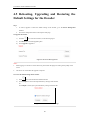
4.5 Rebooting, Upgrading and Restoring the
Default Settings for the Decoder
Steps:
1.
To reboot, upgrade or restore the default settings of the decoder, go to the Device Management
interface.
2.
Choose the configuration items in the left part of the page.
To upgrade the decoder:
1)
Click the
icon to enter the interface, see the following figure.
2)
Click Browse to search the upgrading files.
3)
Click Upgrade to upgrade it.
Figure 4.43 Device Management
Notes:
1.
When logging in to the device for the first time, please install the plug-in according to the prompt on the
screen.
2.
The device will restart after the upgrade is complete.
To restore the default settings of the decoder:
1)
Click
icon to enter the Restore Default interface.
2)
Click Complete to restore the completed factory settings of the decoder.
Or
Click Simple to restore just a part of the factory settings of the decoder.
Figure 4.44 Restore Default Settings
40
User Manual of DS-6400HDI-T Decoder
To reboot the decoder:
1)
Click
icon to enter the rebooting interface.
2)
Click OK if you are sure to reboot the device.
Figure 4.45 Reboot the Device
41
User Manual of DS-6400HDI-T Decoder
CHAPTER 5
Decoder Configuration and Operation by
Client Software
42
User Manual of DS-6400HDI-T Decoder
Run the disk of iVMS-4200 software, and double click the icon to install it in your PC. In this chapter, the basic
procedure of operating the decoder by the software is described.
Please refer to the user manual of iVMS-4200 for more detailed information.
The following figure shows the main interface after accessing to the software:
Figure 5.1 Control Panel
Note: The software is capable of many functions as the controlling and managing for many devices, such as the
DVR, NVR, etc. In this manual, only the operation related to the decoder is introduced.
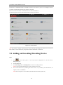
5.1 Adding an Encoding/Decoding Device
Steps:
1.
Click
on the control panel, or click Tools->Device Management to enter the Device
Management page.
2.
Click the Server tab.
3.
Click Encoding Device or Decoding Device to enter device adding interface.
Note: You can click the Add New Device Type to add new device type.
4.
You can add the device by detecting the online devices, or by manually (IP address/domain, IP
segment, IP server or HiDDNS).
Note: The decoding device can be added by IP address/domain and IP segment only.
43
User Manual of DS-6400HDI-T Decoder
Figure 5.2 Add Device by IP Address
Note: Please refer to the User Manual of iVMS-4200 for detailed instructions of adding encoding/decoding
device.
The successfully added decoder device can be viewed in the list.
Figure 5.3 List of Added Decoders
44
User Manual of DS-6400HDI-T Decoder
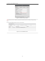
5.2 Setting Video Wall Layout
Steps:
1.
In the control panel, click
2.
Click the
to enter the Video Wall setting interface.
to enter the video wall layout configuration.
Figure 5.4 Video Wall Layout Settings
3.
You can use the default video wall layout or click
to add new layout.
Figure 5.5 Add Screen Information
4.
Edit the video wall name, and enter the number of screens in row and column.
5.
Click Add to finish the adding of the video wall information.
45
User Manual of DS-6400HDI-T Decoder
Notes:
Up to 4 video walls can be added to the client software.
The total number of the display windows of the video wall should be no more than 100.
The ranges of the row number and column number are both between 1 and 10.
6.
Click and drag the output channels on the list of the decoding devices to the display screens.
Figure 5.6 Video Wall Layout
Note: For the DS-6401HDI-T models, the VGA, BNC and HDMI video output interfaces are provided; and
for DS-6404/6408/6410/6412/6416HDI-T, the VGA, DVI-I and BNC video output interfaces are provided.
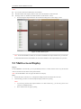
5.3 Multi-screen Display
Purpose:
For DS-6400HDI-T series decoder, you can joint multiple screens as a whole window. In this way, the decoded
video of one camera can be shown on the jointed window.
Note: The DS-6401HDI-T does not support the multi-screen display.
Steps:
1.
Perform the step 6 of Section 5.3 to configure the linkage between the decoder and video wall.
2.
Click-and-drag you mouse to select the adjacent display windows for jointing.
Notes:
1.
You can only joint the same output interfaces as a whole window. E.g., you can only joint 4 VGA
interfaces or HDMI interfaces.
2.
BNC interface does not support jointing.
46
User Manual of DS-6400HDI-T Decoder
Figure 5.7 Multi-screen Display (1)
3.
Click
to confirm jointing the screens.
Figure 5.8 Multi-screen Display (2)
4.
(Optional) You can set the resolution for the jointed window by right-clicking on it and select Decoding
Output Configuration.
To cancel the multi-screen display, click
in the upper-right corner of the display window.
Figure 5.9 Modify Output Parameters
5.4 Displaying Video on Video Wall
Purpose:
After the settings of the encoding device, decoding device and video wall, the video stream from the encoding
devices can be decoded and displayed on the Video Wall.
47
User Manual of DS-6400HDI-T Decoder
Note: After enable decoding and displaying, the captured picture of the video from the encoding device displays
on the Video Wall interface. And the real-time live view is shown on the physical video wall.
5.4.1 Decoding and Displaying Video
Steps:
1.
Click Back to Operation Page to go back to the Video Wall Operation interface.
Figure 5.10 Video Wall Operation Page
2.
Click-and-drag the camera on the left-side list to the display window of video wall. The video stream from
the camera will be decoded and displayed on the Video Wall. You can also select a decoding window and
then double-click a camera to decode and display the video. You can also click and hold the Ctrl or Shift key
to select multiple cameras and then drag them to the video wall.
3.
Select a playing window and click the icon to get a preview of the video in the lower-right corner of the
screen. Or you can directly drag a camera to the preview window for live view. You can also double-click
the preview window to get a full-screen view.
Note: You can move the mouse to the window and click
4.
5.
in the lower-right corner to stop decoding.
(Optional) Select a decoding window and click
to set the window division for it.
If the decoded camera supports PTZ control, you can click beside PTZ to activate the PTZ control panel.
Right-click on a playing window to activate the decoding management menu, as shown below:
Note: The menu differs depending on the devices.
48
User Manual of DS-6400HDI-T Decoder
Figure 5.11 Right-click Menu
Stop / Start Decoding: Stop / Start the decoding.
Start / Pause Successive Decoding: Start / Pause the cycle decoding. This function is only supported by
decoder.
Refresh: Refresh the decoding.
Open / Close Digital Zoom: Enable / Disable digital zoom.
Enable Audio: Turn on / off the audio of the decoding video.
Enlarge Window: Display the window in full-screen mode.
Decoding Channel Status: View the status of the decoding channel, such as decoding status, stream type.
Upload Logo: Upload a picture as the logo to the video window and set the display parameters for it. After
setting, the logo shows in the defined position of the window on physical video wall.
Show / Hide Logo: Show / Hide the logo.
Set Alarm Window: Display the video triggered by event or alarm input on Video Wall.
Go to Playback: Enter the playback mode. This function is only supported by decoder.
Figure 5.12 Video Wall Display
Icon
Description
Start all the decoding
49
User Manual of DS-6400HDI-T Decoder
Stop all the decoding
Stop all the roaming windows
Refresh all the decoding windows
Set cycle decoding and switching interval
5.4.3 Configuring Playback
Purpose:
The record file is supported to be played back on the video wall.
Note: playback function is only supported by decoder.
Steps:
1.
Click-and-drag the camera on the left-side list to the display window of video wall, or you can open a
window if supported.
2.
Move the mouse to the window and click
in the upper-right corner. Or you can right-click on the window
and select Go to Playback in the right-click menu.
3.
If there is record file of current day, the record file will be played back automatically. If not, you can set the
search condition on the search panel which shows in the left area of the interface, and click Search to find
the record file. For detailed configuration about searching record files, please refer to Section 3.2.1 Normal
Playback.
4.
Right-click on the playback window and you can control the playback through the right-click menu, such as
pause, stop, fast forward, slow forward, capture, start recording and full-screen playback.
Note: The saving path for the captured pictures and recorded files can be configured on System
Configuration page.
When you move the mouse to the screen, the icons will display as shown below.
Figure 5.13 Playback the Video File
Icon
Description
Pause the playback
Stop the playback
Capture the playback video
Record the playback video
Back to live view mode
Playback speed.
5.5 Configuring VCA
Purpose:
50
User Manual of DS-6400HDI-T Decoder
The VCA (Video Content Analysis) devices can be added to the client for management, including VCA resource
allocation, shield region settings, rule settings, VCA alarm settings, etc.
5.5.1 Allocating VCA Resource
Before you start:
Before you set the VCA configuration for the added device, you need to configure the VCA resource of the
device to enable the VCA function of the corresponding cameras.
Steps:
1.
In the Video Wall interface, right click on a playing window and select VCA Allocation to enter the VCA
Resource Allocation interface, or you can select the VCA device and click VCA Allocation to activate the
VCA Resource Allocation window in the Device Management Configuration interface.
Figure 5.14 VCA Allocation
Example: In the figure shown above, the VCA type of the device is Behavior Analysis and 12 cameras are
available for configuring VCA settings. And among the 12 cameras, the VCA functions of 5 cameras have
been enabled and the others are disabled.
2.
In the VCA Resource Allocation panel, check
you can uncheck
checkbox to enable the VCA function of the camera. Or
checkbox to disable the VCA function.
5.5.2 Shield Region Configuration
Purpose:
You can set the shield region in which all the VCA rules are invalid.
Steps:
1.
In the Video Wall interface, right click on a playing window and select VCA Configuration to enter the
VCA Config interface.
2.
Click the Shield Region tab in the VCA Config interface to enter the shield region interface. Up to 4 shield
regions can be set.
51
User Manual of DS-6400HDI-T Decoder
3.
Click the
icon, then click and drag the mouse to draw the region, and right-click to finish drawing.
4.
(Optional) Click to select an added shield region, and click
5.
Click Save to save the settings.
to delete it.
Figure 5.15 Set Shield Region
5.5.3 VCA Rule Configuration
Steps:
1.
In the VCA Config interface, click the Rule tab to set the VCA rules.
2.
Check the corresponding checkbox to enable the rule.
Notes:
1) The related operation only takes effect after the rule is enabled.
2) Up to 8 pieces of rules can be added.
3.
To set the rule name, double-click the corresponding rule name area, and input the rule name on your
demand.
4.
Click the event type and select the type in the drop-down list.
The selectable event type depends on the configured VCA type.
Rule and Attribute
Click the Rule and Attribute tab.
Note: The rule should be enabled if you want to modify the rule.
Icon
Description
Delete the selected rule.
Draw the rectangle arming area.
Draw the polygon arming area.
Set the full-screen arming area.
Note: The event type is intrusion.
Draw the virtual line.
Note: The event type is line crossing.
Draw the maximum size filter.
Note: The rule and the size filter should be enabled.
52
User Manual of DS-6400HDI-T Decoder
Draw the minimum size filter.
Note: The rule and the size filter should be enabled.
/
Start/Pause the live view of the camera.
Set the rule
Task1: Draw the virtual line (only for Line Crossing)
1
4
3
Figure 5.16 Draw the Virtual Line
Steps:
1.
Please make sure the rule is enabled and the Rule Type is set as the “Line Crossing” in the area 1 in the
above figure.
2.
Click the
icon in the area 2 and click to set the beginning point in the area 3 and move the mouse to the
end of the line and click again to set another line. Right-click to finish setting the virtual line.
Note: You can click the
icon to draw again.
Task2: Draw the arming region
53
User Manual of DS-6400HDI-T Decoder
1
4
2
3
Figure 5.17 Draw the Arming Region
Steps:
1.
Please make sure the rule is enabled in the area 1 in the above figure.
2.
To draw a rectangle, click the
icon in the area 2 and click to set the top left corner (bottom right corner)
of the region in the area 3 and move the mouse to the bottom right corner (top left corner) and click again.
To draw a polygon, click the
icon and click to select the first corner of the region in the area 3 and move
mouse to one after another corner and click, right-click to finish drawing.
Note: The decagonal region can be supported, and once the tenth point is located, the system will connect it
to the first one with a line automatically.
Attribute
Line Crossing: The detection direction can be modified as “Bidirectional”, “From A to B”, and “From B to A”,
and the detection sensitivity can set.
Intrusion: The detection sensitivity and duration can be modified according to the actual demand.
5.5.4 VCA Alarm Configuration
Steps:
1.
In the VCA Config interface, click the VCA Alarm Config tab to set the VCA alarm.
54
User Manual of DS-6400HDI-T Decoder
Figure 5.18 Set the VCA Alarm
2.
Upload Picture: enable Upload Picture by checking the checkbox, and you can set the quality and
resolution of the VCA picture uploaded to the client software.
Overlay VCA Alarm Logo: enable Overlay VCA Alarm Logo by checking the checkbox, and set the value
of the X-coordinates and Y-coordinates for displaying the VCA alarm logo.
Flicker: enable the VCA logo in flickering mode as demand, and set the flickering time.
Overlay Rules: set the overlay rule if you want to display the target information or rule information on the
alarm picture.
5.5.6 Viewing VCA Alarm Pictures
When you enable the Upload Picture in the VCA alarm configuration interface, the alarm picture of the alarm
armed decoder can be uploaded to the client and viewed in the log information.
Steps:
1.
In the Control Panel, click
to enter the log search and view interface.
2.
Set the start time and end time to search the matched log files.
3.
In the Client Log Lists area, select the log type and the Description Information to VCADEC Alarm.
4.
Set the start time and end time and click Search to search the matched VCA alarm log files and picture
files.
Figure 5.19 View the Alarm Picture
55
User Manual of DS-6400HDI-T Decoder
CHAPTER 6
Appendix
56
User Manual of DS-6400HDI-T Decoder
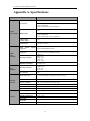
Appendix A. Specifications
Model
DS-6401HDI-T
1-ch
VGA Output
1920×1080@60Hz, 1600×1200@60Hz,
1280×1024@60Hz,
1280×720@50/60Hz, 1024×768@60Hz
1-ch
Audio/
Video Output
Audio/
Video
Decoding
VCA
Decoding
External
Interface
General
HDMI Output
1920×1080@60/50HZ, 1600×1200@60Hz,
1280×1024@60Hz,
1280×720@50/60Hz, 1024×768@60Hz
CVBS Output
(without audio)
1-ch
Audio Output
1-ch, RCA connector
Video Stream
Supported
Format
Audio Stream
Supported
Format
H.264 /MPEG4/MPEG2/Private
G.722/G.711A/G.711U/MPEG2-L2/AAC
Decoding Capability
8MP: 1-ch
5MP: 2-ch;
1080P: 4-ch;
720P: 8-ch;
4CIF: 16-ch
Multi-division Display
1/4/6/8/9/12/16
Decoding Capability
5MP: 1-ch;
1080P: 2-ch;
720P: 4-ch;
4CIF: 8-ch
VCA Channel
2-ch
Network Interface
1; 10/100/1000 Mbps self-adaptive Ethernet interface
Serial Interface
1 RS-232 (DB9), 1 RS-485
Two-way Audio In
1-ch, 3.5 mm connector (2.0 Vp-p, 1 kΩ)
Two-way Audio Out
1-ch, 3.5 mm connector (2.0 Vp-p, 1 kΩ)
Alarm In
Alarm Out
4
4
Power Supply
12 VDC
Power Consumption
Max. 15W
Working Temperature
Working Humidity
Dimensions
(W×D×H)
-10°C ~ 55°C
10% ~ 90%
Weight
≤1.2 kg
220×180×45 mm
57
User Manual of DS-6400HDI-T Decoder
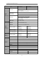
Model
Audio/
Video
Input/Output
Audio/
Video
Decoding
VCA
Decoding
External
Interface
General
DS-6404HDI-T
DS-6408HDI-T
4-ch
8-ch
DVI Output
1920×1080@60/50Hz, 1600×1200@60Hz,
1280×1024@60Hz,
1280×720@50/60Hz, 1024×768@60Hz
CVBS Output
(without audio)
1-ch
DB15 connector (used with the DB15-to-BNC adapter)
1-ch, VGA connector; 1-ch, DVI-I connector
Video Input
1920×1080@60/50Hz, 1600×1200@60Hz,
1280×1024@60Hz, 1280×720@50/60Hz,
1024×768@60Hz, 1280*800@60Hz,
1680*1050@60Hz
Audio Output
8-ch, DB15 connector
Video Stream
Supported
Format
Audio Stream
Supported
Format
H.264 /MPEG4/MPEG2/Private
G.722/G.711A/G.711U/MPEG2-L2/AAC
Decoding Capability
8MP: 2-ch
5MP: 4-ch;
1080P: 8-ch;
720P: 16-ch;
4CIF: 32-ch
8MP: 4-ch
5MP: 8-ch;
1080P: 16-ch;
720P: 32-ch;
4CIF: 64-ch
Multi-division Display
1/4/6/8/9/12/16
1/4/6/8/9/12/16
Screen Jointing Mode
1×2, 1×3, 1×4, 2×1, 2×2
1×2, 1×3, 1×4, 2×1, 2×2, 2×3, 3×2,
2×4, 4×2
Decoding Capability
5MP: 2-ch;
1080P: 4-ch;
720P: 8-ch;
4CIF: 16-ch
5MP:4-ch;
1080P: 8-ch;
720P: 16-ch;
4CIF:32-ch
VCA Channel
10-ch
12-ch
Network Interface
1; 10/100/1000 Mbps self-adaptive Ethernet interface
Serial Interface
1 RS-232 (DB9), 1 RS-485
USB Interface (reserved)
2, USB 2.0
Two-way Audio In
1-ch, 3.5 mm connector (2.0 Vp-p, 1 kΩ)
Two-way Audio Out
1-ch, 3.5 mm connector (2.0 Vp-p, 1 kΩ)
Alarm In
Alarm Out
4
4
Power Supply
100~240VAC
Power Consumption
Max. 108W
Working Temperature
Working Humidity
Dimensions
(W×D×H)
-10°C ~ 55°C
10% ~ 90%
440×340×70 mm
440×340×70 mm
Weight
≤5.2 kg
≤5.2 kg
58
User Manual of DS-6400HDI-T Decoder
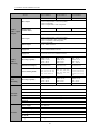
Model
Audio/
Video Input/
Output
Audio/
Video
Decoding
VCA
Decoding
External
Interface
General
DS-6410HDI-T
DS-6412HDI-T
DS-6416HDI-T
10-ch
12-ch
16-ch
DVI Output
1920×1080@60/50Hz, 1600×1200@60Hz,
1280×1024@60Hz,
1280×720@50/60Hz, 1024×768@60Hz
CVBS Output
(without audio)
5-ch
6-ch
8-ch
DB15 connector (used with the DB15-to-BNC adapter)
1-ch, VGA connector; 1-ch, DVI-I connector
Video Input
1920×1080@60/50Hz, 1600×1200@60Hz,
1280×1024@60Hz, 1280×720@50/60Hz,
1024×768@60Hz, 1280*800@60Hz,
1680*1050@60Hz
Audio Output
16-ch, DB15 connector
Video Stream
Supported
Format
Audio Stream
Supported
Format
H.264 /MPEG4/MPEG2/Private
G.722/G.711A/G.711U/MPEG2-L2/AAC
Decoding Capability
8MP: 5-ch
5MP: 10-ch;
1080P: 20-ch;
720P: 40-ch;
4CIF: 80-ch
8MP: 6-ch
5MP: 12-ch;
1080P: 24-ch;
720P: 48-ch;
4CIF: 90-ch
8MP: 8-ch
5MP: 16-ch;
1080P: 32-ch;
720P: 64-ch;
4CIF: 100-ch
Multi-division Display
1/4/6/8/9/12/16
1/4/6/8/9/12/16
1/4/6/8/9/12/16
Screen Jointing Mode
1×2, 1×3, 1×4, 2×1,
2×2, 2×3, 2×4, 2×5,
3×2, 3×3, 4×2, 5×2
1×2, 1×3, 1×4, 2×1,
2×2, 2×3, 2×4, 2×5,
3×2, 3×3, 4×2, 5×2,
3×4, 4×3
VCA Channel
5MP: 5-ch;
1080P: 10-ch;
720P: 20-ch;
4CIF: 40-ch
10-ch
5MP: 6-ch;
1080P: 12-ch;
720P: 24-ch;
4CIF: 48-ch
12-ch
Network Interface
1; 10/100/1000 Mbps self-adaptive Ethernet interface
Serial Interface
1 RS-232 (DB9), 1 RS-485
USB Interface (reserved)
2, USB 2.0
Two-way Audio In
1-ch, 3.5 mm connector (2.0 Vp-p, 1 kΩ)
Two-way Audio Out
1-ch, 3.5 mm connector (2.0 Vp-p, 1 kΩ)
Alarm In
Alarm Out
4
4
Power Supply
100~240VAC
Power Consumption
Max. 108W
Working Temperature
Working Humidity
Dimensions
(W×D×H)
-10°C ~ 55°C
10% ~ 90%
Weight
≤6.4 kg
Decoding Capability
440×340×88 mm
59
1×2, 1×3, 1×4,
2×2, 2×3, 2×4,
3×2, 3×3, 4×2,
3×4, 4×3, 5×3,
4×4
5MP: 8-ch;
1080P: 16-ch;
720P: 32-ch;
4CIF: 64-ch
16-ch
2×1,
2×5,
5×2,
3×5,
User Manual of DS-6400HDI-T Decoder
Appendix B. FAQ
Why cannot ping the decoder?
1.
Check the cable and the switch.
2.
Please refer to Chapter 3 to configure the IP address of the decoder.
Why cannot connect the decoder with client software?
1.
Check the decoder IP address.
2.
Cable is connected.
3.
User name and password of decoder are correct.
Why cannot play back the record files in DVR with decoder?
1.
Check the DVR network connection.
2.
Check the parameters of the playback file.
3.
Check if there are files existed in the selected time duration.
Why cannot decode the stream transported by stream media server?
1.
Check the network connection between decoder and stream media server.
2.
Check if the stream media server port is connected with the port added on decoder.
60
User Manual of DS-6400HDI-T Decoder
Appendix C. List of Third-party IP Cameras
Access
IP Camera
Manufacturer
Model
Supported Video Format
SP306H
Panasonic
SP336H
SNC-CH220
Sony
SNC-RH124
P5532
Axis
Q7404
Sanyo
VCC-HD2500P
Bosch
NBC265P
Zavio
D5110
Arecont
AC1305M
Pelco
IX30DN-ACFZHB3
Onvif
Supported
61
H.264, MPEG4