1
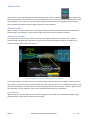
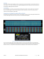
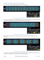
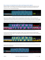
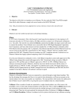
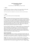
Manchester-NRZ Decoder, Documentation for Beta Testers August 2012/January 2013/Oct 2015 Table of Contents Manchester-NRZ Decoder, Documentation for Beta Testers ...............................................................................1 1. Introduction ..................................................................................................................................................3 2. Fundamental mental model..........................................................................................................................4 3. Getting started ..............................................................................................................................................5 4. The Basic Tab, Bit Level Decoding .................................................................................................................7 Bit Rate .............................................................................................................................................................................. 7 Idle State ........................................................................................................................................................................... 7 Encoding ............................................................................................................................................................................ 7 Timeout Units .................................................................................................................................................................... 8 Timeout in Bits .................................................................................................................................................................. 8 Timeout in Seconds ........................................................................................................................................................... 8 Use Timeout ...................................................................................................................................................................... 8 Polarity (Manchester Standard and NRZ) ......................................................................................................................... 9 The different Manchester Encoding Types ..................................................................................................................... 10 Verifying the Bit Level Decode ........................................................................................................................................ 11 5. The Decode Tab ......................................................................................................................................... 12 The Data Mode................................................................................................................................................................ 12 Decoding into Bits ........................................................................................................................................................... 12 First Transition Used (FTO) .............................................................................................................................................................12 Bit Stretch Tolerance ......................................................................................................................................................................12 Interpretation of the Manchester bits, tuning of Bit Slicer. ............................................................................................................13 Decoding into Words ...................................................................................................................................................... 13 Converting Burst Bits into Words....................................................................................................................................................13 The Viewing ....................................................................................................................................................................................14 Bit Order .........................................................................................................................................................................................14 Sync Bits ..........................................................................................................................................................................................14 PrePad Bits ......................................................................................................................................................................................14 The Nx Factor ..................................................................................................................................................................................14 Data Bits ..........................................................................................................................................................................................15 Post Pad Bits ...................................................................................................................................................................................15 Comparison of a Signal Decoded as Bits or Words ......................................................................................................... 15 Comparison of Signal Decoded with varying Nx ............................................................................................................. 16 6 The Level Tab .................................................................................................................................................. 17 The contents and actions of the controls in the Level Tab ............................................................................................. 17 How to tune Level and hysteresis when working on noisy signals ................................................................................. 19 A philosophical comment and a word of caution ........................................................................................................... 20 Technical information ........................................................................................................................................ 20 Lahniss Manchester-NRZ BUS Documentation Page |1 List of Figures Figure 1: Complexity ladder of protocols ..............................................................................................................3 Figure 2: A Burst of Raw Data ...............................................................................................................................5 Figure 3: The Signal Source and Protocol Selection Dialog ...................................................................................5 Figure 4: The 3 tabs (Basic, Decode, Levels) driving Manchester-and NRZ decode. ............................................6 Figure 5: The Basic Tab..........................................................................................................................................7 Figure 6: Example of a Timeout Definition (Use Timeout assumed) ....................................................................8 Figure 7: Manchester Physical to Logical mapping, case Falling = 0 .....................................................................9 Figure 8: Manchester Physical to Logical mapping, case Falling = 1 .....................................................................9 Figure 9: Manchester Standard, Falling=0, Rising=1 .......................................................................................... 10 Figure 10: Manchester Standard, Falling=1, Rising=0 ........................................................................................ 10 Figure 11: Differential Bi-Phase Mark, always Midbit change, "1" no change at bit start and "0" changes ..... 10 Figure 12: Differential Bi-Phase Space, always Midbit change, "0" no change at bit start and "1" changes .... 10 Figure 13: Correct NRZ decoding at 1 Mb/s ....................................................................................................... 11 Figure 14: Incorrect NRZ Bit level decoding of same signal at 2 Mb/s .............................................................. 11 Figure 15: Incorrect NRZ Bit level Decode, the bits are not aligned with the transitions ................................. 11 Figure 16: Incorrect NRZ Bit Level Decode, gaps between the bits ................................................................... 11 Figure 17: Decode Tab in Bit Mode .................................................................................................................... 12 Figure 18: The Table Mode selection popup ..................................................................................................... 12 Figure 19: Examples of Interaction between FTO and decoding ....................................................................... 13 Figure 20: Table view, with too many 2s and 3s in Data ................................................................................... 13 Figure 21: Decoding a Burst into 2 Words, Decode Tab in Word Mode (no Nx field in this image, pre 7.9) .... 14 Figure 22: Comparison of Bit and Word Decode on the same signal. ............................................................... 15 Figure 23: Payload bits grouped as repeated <1|1x8|2> blocks ....................................................................... 16 Figure 24: Payload bits grouped as single <16|12x8|13> blocks ...................................................................... 16 Figure 25: Payload bits grouped as repeated <4|2x8|5> blocks ....................................................................... 16 Figure 26: The Level Tab, with default settings ................................................................................................. 17 Figure 27: Effect of the Level and Hysteresis values on the decoding............................................................... 17 Figure 28: Heavily zoomed image of the Level and Hysteresis rendering. ....................................................... 18 Figure 29: Correct decode of a clean Signal, Level 50%, Hysteresis 15% .......................................................... 19 Figure 30: Wrong decode of the same signal, heavily perturbed, Level 50% and Hysteresis 15% ................... 19 Figure 31: Correct decoding on Noisy Signal, with Level at 50% but Hysteresis at 3 Divisions ......................... 19 Figure 32 Correct decoding on Filtered Signal, with Default level and Hysteresis ........................................... 19 Lahniss Manchester-NRZ BUS Documentation Page |2 1. Introduction The Manchester-NRZ Decoder developed by Lahniss for LeCroy oscilloscopes is a tool aimed at decoding serial data that is not supported by main stream decoders, and whose structure is reasonably simple to be described with the 10-20 controls explained below. It was born out of recurring customers request for decoding fairly simple serial data, not belonging to the historical protocols such as I2C, UART and SPI, or the dedicated protocols such as CAN, LIN, MIL-1553, ARINC 429, MIPI, Ethernet, etc…. The diagram below exemplifies the situation. Figure 1: Complexity ladder of protocols In that spirit, the user is required to configure a number of controls, making it possible for the general algorithms to execute on his particular signal. This process requires a little more knowledge of serial data encoding logic than previous decoders, but the explanations below should shed some light on the procedure. Once the setting have been determined for a given signal, they can be stored in normal panel files and recalled later, when analysis on the same signal are required. In its current form, the configurable Decoder operates on NRZ or Manchester streams. The product will handle digitally encoded data on a single signal, with 2 levels (High and Low), a constant Bitrate between 10 bit/sec to 60 Gb/sec at any voltage levels and a timeout(or Inter Frame Gap) allowing to separate bursts of data on the line. The product will not handle multi line signals, signals with more than 2 voltage levels, stuff bits and or complex synchronization pulses. This product, whilst flexible, is not suitable for complex protocol streams such as i.e. CAN, CAN FD, MIL-STD1553, FlexRay, MIPI or 2 or 3 signal transmissions such as I2C or SPI. For these protocols, the dedicated decoders are available. So this software component is more of a toolbox aimed at supporting many different streams that have some basic characteristics in common, and a limited market that does not justify a dedicated decoder. Lahniss Manchester-NRZ BUS Documentation Page |3 2. Fundamental mental model Before we get started, we need to emphasize the methodology underlying the software described here. The fundamental model is a 3 step model. The signal needs to be decoded as: Burst(s) first with their constitutive Transitions, based on the Bitrate and the Timeout Definition. Bursts are separated by “Holes” or electrically speaking quiescent times on the transmission line. Then each Burst needs to be sliced into Bits using the Transitions, the Bitrate and Polarity and the Type either NRZ or Manchester. Finally the Bursts of Bits can be converted to Words using the Bits previously extracted, and based on grouping rules The Bit conversion will not be functional before the Bursts are correctly separated with their Transitions, and the Words extraction will not function correctly until the Bits are properly decoded. The process is a 3 level stepwise method. The tuning of the Decoder must therefore be conducted in this order: Transitions Bits Words. The following material will guide the operator through every step of the process, beginning at the Transitions level and ending at the Words level. Lahniss Manchester-NRZ BUS Documentation Page |4 3. Getting started In order to get started with the Manchester-NRZ Decoder, it is advisable to adjust the scope controls to acquire one Burst or Frame of relevant Data, and then stop the acquisition. The data Burst should be reasonably well centered on screen, in both directions, with generous idle segments on both sides. Figure 2: A Burst of Raw Data Once the Burst of Data to be decoded is acquired, we will proceed to its interpretation using either the Manchester or the NRZ Decoder. We will proceed gradually; starting with the identification of the Burst controls, then extract the Bits and finally the Words, by grouping the Words. The words “Burst, “Frames” or “Packets” are used in interchangeable manner in this document, and in general literature. Later we will address the decoding of many Packets into the same record, therefore allowing the observation of the encoded data values over a period of time. The decoder settings determined on a few packets will be reused when handling many packets. In order to start the decoding we need to be familiarized with the User Interface of the Decoder. Firstly, in the Serial Decode dialog, you need to select the signal source (here C1), and the Protocol, “Manchester” in this case. Figure 3: The Signal Source and Protocol Selection Dialog Once the “Manchester” or “NRZ” Protocol has been selected 3 tabs will appear in the Right Hand Side Dialog. We will be setting various values in these 3 tabs (Basic, Decode, Level). When working on a given signal, some of the values in the tabs will not change anymore because they are strongly linked to the signal (i.e. Bit Rate or Polarity). Other values will have to be tuned to obtain optimal results. Some of the controls can be used to reverse engineer unknown signals Lahniss Manchester-NRZ BUS Documentation Page |5 Figure 4: The 3 tabs (Basic, Decode, Levels) driving Manchester-and NRZ decode. The “Use Timeout” selection allows decoding of continuous streams when unchecked. Lahniss Manchester-NRZ BUS Documentation Page |6 4. The Basic Tab, Bit Level Decoding The Basic tab presents all the fundamental controls necessary to allow proper bit level decoding. We will look at each control individually. Figure 5: The Basic Tab Bit Rate Introduce the Bit Rate of your signal here, as precisely as you know it. Hardware engineers working on a design often know the Bit Rate. If you are not sure about the value, use the cursor read outs, on one single bit or a sequence of bits to determine the exact Bit Rate of your signal. The value should be correct within about 5%. Note that a mismatched Bit Rate will cause various confusing side effects on the decoding, so it is best to take time to correctly adjust this fundamental value. Bit Rates can be selected from 10 bits/s to 10 Gb/s. Idle State The idle State complements the Timeout value set previously. In order to declare that a new Burst has to be started, the algorithm looks at the time elapsed between 2 consecutive Transitions, as well as the state of the idle level between these transitions. This mechanism allows a precise definition of what the separation gap between 2 Bursts should be. In most cases, the idle state is specified, and therefore provides an additional condition to the timeout to define the Burst start. If this distinction is not desired, select “Don’t care” in the popup box. Encoding The encoding control (Manchester only) allows the selection of several Manchester flavors. When Standard is selected the Polarity control is visible, when any other encoding is chosen, the Polarity disappears. The differences will be explained below, with exemples. Lahniss Manchester-NRZ BUS Documentation Page |7 Timeout Units The Timeout, or Gap, separating Burst can be selected either in Bits or Seconds. Both methods are perfectly equivalent in terms of their results, but depending on the context, the protocol specifications or the user preference, one or the other representations might be chosen. Note that regardless of the Timeout Units selected, the allowed Timeout range will be from 1 bit to 100 bits. Timeout in Bits When a Timeout in bits is selected, as in our example above, the system will use the Bit Rate to determine the Bit Length, and multiply it by the number of bits selected to obtain a Timeout in seconds. Timeout in Seconds As an alternative to the Timeout in Bits, the value can be expressed directly in seconds. This is useful in protocols with a timeout spec expressed in time units. The following image provides an example of the controls and their effect on the annotation. Figure 6: Example of a Timeout Definition (Use Timeout assumed) In the Figure above, a Timeout of 2 micro-seconds has been selected. The grey rectangle on the trace shows this timeout, as well as the value selected by the user. Note that the value of 2 us is adequate to separate the 2 Bursts of transmission. Furthermore, this protocol requires the timeout span to be “Idle low” which is set in the “Idle State” control. “Idle low” refers to the Threshold level marked as a dotted line. Use Timeout When this control is unchecked, the stream will no longer be packetized. This is sometimes useful on high speed protocols, which have continuous bit streaming. Lahniss Manchester-NRZ BUS Documentation Page |8 Polarity (Manchester Standard and NRZ) The Manchester “Polarity” governs the conversion of the physical signal transition into a logical bit state. In Manchester When Falling=0 is chosen, a falling edge through the threshold level, will be decoded as a logical Zero, whereas a rising edge through the threshold level, will be decoded as a logical One. The NRZ “Polarity” governs the conversion of the physical signal transition into a logical bit state. When Low=0 is chosen, a low level signal state (below threshold) will translate as a logical zero whereas a high level (above threshold) signal will translate as a logical 1. The opposite logic will apply when Low=1 is selected. The image below shows a Manchester example Figure 7: Manchester Physical to Logical mapping, case Falling = 0 When Falling=1, the opposite logic will be applied, leading to the following image of the low level decode annotation: Figure 8: Manchester Physical to Logical mapping, case Falling = 1 Lahniss Manchester-NRZ BUS Documentation Page |9 The different Manchester Encoding Types There exists a great variety of Manchester encoding. The current implementation supports the 4 versions, documented on this page. A stream of about 40 bits is shown in every case, and allows the association of the physical signal with the logical signal according to the encoding at hand. Manchester Standard, Falling = 0 Figure 9: Manchester Standard, Falling=0, Rising=1 Manchester Standard, Falling = 1 Figure 10: Manchester Standard, Falling=1, Rising=0 Differential Bi-Phase Mark Figure 11: Differential Bi-Phase Mark, always Midbit change, "1" no change at bit start and "0" changes Differential Bi-Phase Space Figure 12: Differential Bi-Phase Space, always Midbit change, "0" no change at bit start and "1" changes Lahniss Manchester-NRZ BUS Documentation P a g e | 10 Verifying the Bit Level Decode We have now covered all the controls in the Basic tab. When all of these values are set we should already have a basic bit level decoding on the trace selected as a source. Note that by default the Data Mode is set to bits, so that the setting of the second tab do not matter for the initial bit level decode. The following picture shows a correct decoding, the bit transitions are all aligned with the signal transitions, the logical interpretation of the bits are consistent with the physical level, in this case Physical High equals logical 1. Figure 13: Correct NRZ decoding at 1 Mb/s Note that the decoding at an exact multiple of the bitrate could seem correct, but would not allow further interpretation of the words. This image shows the decoding of the same signal portion at twice the bitrate. Figure 14: Incorrect NRZ Bit level decoding of same signal at 2 Mb/s A great suspicion is appropriate when the bits are not aligned with the transitions, as per next example. Figure 15: Incorrect NRZ Bit level Decode, the bits are not aligned with the transitions Also suspect is a bit stream that would look like the following image, with gaps between the bits. Figure 16: Incorrect NRZ Bit Level Decode, gaps between the bits The next section will refine the interpretation and take the decoding one level of abstraction higher, the word level. Lahniss Manchester-NRZ BUS Documentation P a g e | 11 5. The Decode Tab The bit level decode reached in the previous section can be taken further, so that some transitions are skipped, and subsequent bits are grouped into words, and the words interpreted lsb first or msb first. We will not explain the classical encoding schemes here but refer to selected Internet contributions i.e. as in: http://ckp.made-it.com/encodingschemes.html http://www.rhyshaden.com/encoding.htm The following image shows the decode tab, when Data Mode is “Bits”. In this Mode, most of the controls are grayed out indicating that they have no action. As soon as we select “Data Mode” as Words, the grayed out fields will become active. Figure 17: Decode Tab in Bit Mode The Data Mode This control drives the level of decoding desired. Initially make sure you select “Bits”. “Bits”is also the default value when starting the decoder. Figure 18: The Table Mode selection popup Decoding into Bits We have already looked at the low level decoding in bits in the previous section. There are a few more items to look at as part of the Bit Level decoding. Then we will address the Word level decoding. First Transition Used (FTO) Many Manchester or NRZ encoding schemes utilize a preamble, a synchronization sequence, or a voluntary Manchester violation. The FTO can be used to start the decoding after the violation, where the real data payload starts. It avoids the intricacies of dedicated protocols in the initial segment of each packet. Bit Stretch Tolerance The Manchester bit slicer hops from midbit to midbit. However, due to hardware or signal propagation issues, the midbits might not be perfectly equidistant. In this case the tolerance can be manually increased to attempt to decode jittery signals. Conversely, it can be decreased until the decoding starts showing anomalies, to assess the stability of the midbit distribution. Lahniss Manchester-NRZ BUS Documentation P a g e | 12 Interpretation of the Manchester bits, tuning of Bit Slicer. When decoding a serial stream as a Manchester, it is normally expected to see Ones and Zeroes as explained above. It is however possible that 2’s and 3’s appear in the decoded stream. These values correspond to violations for the Manchester rules, stating there must be a transition at midbit. Figure 19: Examples of Interaction between FTO and decoding These violations can be voluntary, as in the MVB (Multiple Vehicle Bus) example above. They often correspond to synchronization patterns used by the hardware to start the decoding. In other cases the Highs and Lows carry information and allow the detection of different Frame types. There is a nearly endless set of combinations used in various protocols. The initial part of the Manchester packet is called different names in different protocols: Preamble, Start Of Frame, Packet Header, Packet Start, etc. In order to obtain a correct decoded stream, the user needs to set the FTO in a way that the bits are correctly synchronized throughout the packet. Usually this can be achieved by setting the Bitrate first as in the previous section. Then The Transition Tolerance might have to be enlarged from its default of 20% (see above). When the signal is stable it might be decreased to less than 5 % without changing the output of the Decoder observed in the table. In the example below, the many 2s and 3s in the Data indicate an incorrect phasing of the bit decoder with the signal. More tuning is required before the Word Level can be used. Figure 20: Table view, with too many 2s and 3s in Data Note that the Word decoder will silently process bits with values of 2 and 3, but the results will be incorrect. Decoding into Words We have now achieved a correct bit level decoding, and we can look at higher level concepts. Converting Burst Bits into Words This is achieved by selecting the Data Mode “Words”. When this mode is selected, all of the fields become accessible. Unlike decoding into bits, the conglomeration of bits into words does no longer depend upon the physical layer. In other words, the bits can be grouped to form words, regardless of their origin (NRZ, Manchester or else). As a consequence the mechanisms described below apply to both the NRZ and the Manchester Decoders. Lahniss Manchester-NRZ BUS Documentation P a g e | 13 The tools offered by the Decoders allow a grouping of bits into PrePad, Data Bits, and PostPad The next image shows an example, with the corresponding annotations. Figure 21: Decoding a Burst into 2 Words, Decode Tab in Word Mode (no Nx field in this image, pre 7.9) The Viewing This control will be used to choose how we want to view the PrePad, Data Bits, and PostPad, both in the table and the annotations on the trace. This parameter has no impact when “Data Mode” is “Bits” and is therefore grayed out. Bit Order When decoding in “Words” this control selects a conversion of the Word with the Most Significant Bit first or the Least Significant Bit first. This parameter has no impact when “Data Mode” is “Bits” and is therefore grayed out. Sync Bits The “Sync Bits” lets the user choose at which bit the packetizing should start. The algorithm will start at “Sync Bits” and group bits into the 3 fields “PrePad”, “Data Bits” and “PostPad”. Then it will restart with the “PrePad” of the next sequence. There might be 0 to 100 Sync Bits. PrePad Bits The “PrePad Bits” are used to group information preceding the Data Bits. There might be 0 to 32 PrePad Bits. PrePad bits might be used to group Address bits, Preambles, Subaddress, etc… The Nx Factor This value allows the replication of several Data Words defined by the Data bits. Its default is 1, meaning that there is only one Data word with the defined number of Data bits. When the value is set to one, the grouping of bits into words occurs as a repeated sequence of <Prepad|Data|PostPad> blocks. When the value is greater than 1, for example 3, the grouping of bits will occur as a repeated sequence of <Prepad|Data|Data|Data|PostPad> blocks. Examples are shown below. Lahniss Manchester-NRZ BUS Documentation P a g e | 14 Data Bits The number of bits grouped together to form a single word. The “Bits per Words” can take values from 1 to 32 in steps of 1. This value is essential when using ProtoBusMAG because it allows the correct extraction of the bit field for MessageToValue parameter. Post Pad Bits The “PostPad Bits” are used to group information following the Data Bits. There might be 0 to 32 PostPad Bits. Post Pad bit might be used to visually represent a CRC, a checksum, a Value or any other protocol construct. There is however no CRC check. Comparison of a Signal Decoded as Bits or Words The following annotated screen dump provides a time aligned comparison of the same signal decoded as bits or words. Here again the action of every control can be verified and explained Figure 22: Comparison of Bit and Word Decode on the same signal. This case shows an NRZ signal, physical high and logical 1. The 127 bits of both signals are time aligned to allow an easy understanding of how the Prepad, Data and PostPad fields get constructed. Note that here the Nx factor is set to 1, to only allow one Data field. The subsequent section will show other combinations. Lahniss Manchester-NRZ BUS Documentation P a g e | 15 Comparison of Signal Decoded with varying Nx This section shows the same signal decoded using 3 common variations. Figure 23: Payload bits grouped as repeated <1|1x8|2> blocks This structure is frequently found in UART type protocols, when consecutive characters are being transmitted over the line. Each character is made up of a start bit(s), data bits and stop bit(s). Figure 24: Payload bits grouped as single <16|12x8|13> blocks Another frequently found structure with an initial ID, or Destination, several adjacent Data bytes and a trailing field. Figure 25: Payload bits grouped as repeated <4|2x8|5> blocks This structure is less frequent, but possible, and combines above examples into blocks. The use of the above controls allows a flexible and rich decomposition of the payload databits. Lahniss Manchester-NRZ BUS Documentation P a g e | 16 6 The Level Tab The contents and actions of the controls in the Level Tab The last tab to be discussed is the level tab. The image below shows its contents Figure 26: The Level Tab, with default settings The next image will show the effect of the controls when using the percent mode. Figure 27: Effect of the Level and Hysteresis values on the decoding When working in percent, all the values are proportional to the 100% signal amplitude. In the example, the level of 68% refers to the 100% amplitude shown. The same applies to the Hysteresis. Both Level and Hysteresis can be switched to “Type=Absolute”. In this case the values need to be set in Volts. Both methods have their merits. It is also possible to use the Level in one Mode (i.e. Absolute) whereas Hysteresis is in the other Mode (i.e. Percent). In general, the Percent Mode is more convenient and faster to setup because it immediately determines the optimal threshold. However, on poor signals the Percent Mode can fail and lead to bad decodes. Then it might help to use the Absolute Mode. On very long signals, the Percent Mode adds computational load. If performance is an issue, it might be beneficial to switch to Absolute mode. Before we continue, let’s emphasize the visual rendering of Level and Hysteresis again. Hysteresis is fairly subtle as it should not dominate the rendering of the decoded information. Lahniss Manchester-NRZ BUS Documentation P a g e | 17 Figure 28: Heavily zoomed image of the Level and Hysteresis rendering. In this Figure the level appears as a blue dotted line (highlighted with a blue circle) while the Hysteresis is annotated as a dark grey band (yellow line) The next section will discuss an example of a bad signal decoded by tuning the Level and hysteresis settings. Lahniss Manchester-NRZ BUS Documentation P a g e | 18 How to tune Level and hysteresis when working on noisy signals We will now look at an example of a noisy signal that will not decode correctly with the default Level and Hysteresis values. The first image shows the reference decoding of a clean Manchester signal, with 16 transitions, 11 bits of values 000-1101-0100 Figure 29: Correct decode of a clean Signal, Level 50%, Hysteresis 15% When noise is added to the signal, various wrong decoding symptoms appear, such as 2’s and 3’s, non contiguous bits, too many transitions (here 37) and fake bits on the idle portion. The reason is that the signal spikes create fake transitions where it crosses the Level Threshold with insufficient hysteresis. (Red markers). Note that if we were decoding in Word Mode, other errors would appear, but with the same root cause. Figure 30: Wrong decode of the same signal, heavily perturbed, Level 50% and Hysteresis 15% As soon as we increase the hysteresis, the spikes no longer cross the hysteresis band and the decoding converges back to correct values. In this image note the expanded Hystersis annotation band around the bue dotted level marker line. Figure 31: Correct decoding on Noisy Signal, with Level at 50% but Hysteresis at 3 Divisions Finally another method using a numerical Filter (Median Filter) to smoothen the noise and still decode with default Level and Hysteresis. Figure 32 Correct decoding on Filtered Signal, with Default level and Hysteresis Lahniss Manchester-NRZ BUS Documentation P a g e | 19 A philosophical comment and a word of caution Although the above numerical tricks have shown that it is possible to decode a noisy or corrupted signal, these techniques do not replace the fundamental healthy signal hygiene. Having good signal is the best way to avoid system failures or performance degradation. The decoding techniques are meant to help until the signal is fixed. There are many reasons for having poor signals: bad lines, poor components at every level in the circuitry, EMC issues and many more, and last but not least wrong probing techniques or even faulty oscilloscope. The discussion of those is outside the realm of this manual, but should be taken seriously. Technical information A burst might contain at most 100000 transitions, or 32000 bits or 1000 words, whichever occurs first. This is merely a safety limit for software engineering reasons then a limit based on any protocol. The Bit rate limit is not an algorithmic limitation, but rather is based on the availability of test signals for the extreme cases. As for other decoders, the limit might be expanded if and when signals at those speed are available to validate the algorithm. Lahniss Manchester-NRZ BUS Documentation P a g e | 20