1
Lab 7: Introduction to Ethernet
EE-379 Embedded Systems and Applications
Electrical Engineering Department, University at Buffalo
Last update: Cristinel Ababei, April 2013
1. Objective
The objective of this lab is to introduce you to Ethernet. We also study the EMAC EasyWEB example
(from Keil) which illustrates a simple web server hosted on the MCB1700 board.
Note: This presentation has been adapted from various references listed at the end of this lab.
2. Ethernet
Ethernet is now the world's most pervasive networking technology.
History
In 1973 Xerox Corporation’s Palo Alto Research Center began the development of a bus topology LAN
(local area network). In 1976 Xerox built a 2.94 Mbps network to connect over 100 personal workstations
on a 1 km cable. This network was called the Ethernet, named after the ether, the single coaxial cable used
to connect the machines. Xerox Ethernet was so successful, that in 1980 Digital Equipment Corporation,
Intel Corporation, and Xerox had released a de facto standard for a 10 Mbps Ethernet, informally called
DIX Ethernet (from the initials of the 3 companies). This Ethernet Specification defined Ethernet II and was
used as a basis for the IEEE 802.3 specification in 1985. Strictly, "Ethernet" refers to a product which
predates the IEEE 802.3 Standard. However nowadays any 802.3 compliant network is referred to as an
Ethernet. Ethernet has largely replaced competing wired LAN technologies.
Over the years Ethernet has continued to evolve, with 10Base5 using thick coaxial cable approved in 1986,
10Base2 using cheaper thin coaxial cable approved in 1986. Twisted pair wiring was used in 10BaseT,
approved in 1991 and fiber optic in 10BaseF, approved in 1994-95. In 1995, 100Mbps Ethernet was
released, increasing the speed of Ethernet, which has since been further increased with the release of
Gigabit Ethernet in 1998-99. In 2002, 100 Gigabit was published and recently 100 Gigabit Ethernet (or
100GbE) and 40 Gigabit Ethernet (or 40GbE) emerged and were first defined by the IEEE 802.3ba-2010
standard. In the future, Ethernet will continue to increase in speed.
Broadcast Network Operation
Ethernet is a Broadcast Network: hosts are connected to a network through a single shared medium. This
has the advantage that messages don't have to be routed to their destination, as all hosts are present on the
shared medium, but it does incur another set of problems. The main problem which needs to be addressed is
that of Media Access Control (MAC) or giving fair access to multiple nodes on a shared medium.
Collisions: When a number of nodes are connected to a single shared medium, one of the issues is the
possibility of two or more nodes trying to broadcast at the same time. This is called a collision and prevents
any information passing along the network because the multiple messages would corrupt each other,
destroying both. There are two main methods for reducing the effect of collisions 1) Collision Avoidance
and 2) Collision Resolution. Collision Avoidance involves systems which prevent any collisions occurring
1
in the first place, such as polling or token passing. Collision Resolution or Contention MAC Strategies rely
on the fact that collisions will occur, and try to cope with them as well as possible. Ethernet uses Collision
Resolution. Below, we discuss some collision resolution techniques.
ALOHA: The most basic form of Collision Resolution is to simply allow any station to send a message (or
packet) whenever it is ready to send one. This form of transmission was first used in a prototype packet
radio network, ALOHANET, commissioned in Hawaii in 1970, and has been known ever since as unslotted
ALOHA. In Pure ALOHA, packets contain some form of error detection which is verified by the receiver.
If the packet is received correctly, the destination returns an acknowledgment. If a collision occurs and the
message is destroyed or corrupted, then no acknowledgment will be sent. If the sender does not receive an
acknowledgment after a certain delay, it will re-send the message.
Carrier Sense Multiple Access (CSMA): The next stage in Collision Resolution after ALOHA was to add
the ability for devices to detect whether the shared medium is idle or not. This is called "Carrier Sense
Multiple Access" or CSMA. This, however, does not completely eliminate collisions, since two devices
could detect the medium as idle, then attempt to send at approximately the same time.
CSMA is actually a family of protocols which vary by the method which they wait for the medium to
become idle, known as the persistence strategy. Here is a list of two major strategies:
1-Persistent CSMA - In this strategy, when a device wants to send a message, it first listens to the
medium. If it is idle the message is sent immediately, however, if it is busy the device continues to
listen to the medium until it becomes idle and then sends the message immediately. The problem is that
if a number of devices attempt to send during a busy period, then they shall all send as soon as the
medium becomes idle, leading to a collision.
nonpersistent CSMA - This strategy attempts to reduce the greediness of 1-Persistent CSMA. It again
first listens to the medium to see if it is idle, if so it sends immediately. If the medium is busy, instead
of continuing to listen for the medium to become idle and transmitting immediately, it waits a random
period, then, it tries again. This means that in high load situations, there is less chance of collisions
occurring.
Collision Window: A collision occurs when two devices send at approximately the same time. But how
long does a device have to wait until it knows that its message has not been corrupted by a collision?
Messages take a certain amount of time to travel from the device to the end of the signaling medium, which
is known as the propagation delay. It would seem that a device only needs to wait for one propagation
delay, until the message reaches the last receiver, to know if a collision has occurred. This, however, is not
the case. Take for example the following situation. A device sends a message, which takes 1 propagation
delay to reach the last device on the medium. This last device on the medium could then send a message
just before the original message reaches it (i.e., just before 1 propagation delay). This new message would
take an additional propagation delay to reach the original device, which means that this device would not
know that a collision had occurred until after 2 propagation delays.
Collision Detection: Knowing how long is needed to wait to discover if a collision has occurred, we can
use this to increase the effectiveness of CSMA. CSMA behaves inefficiently when a collision occurs, since
both stations continue to send their full packet, even though it will be corrupted. A simple enhancement to
CSMA is the addition of Collision Detection (CSMA/CD). A simple check is made to make sure that the
signal present on the medium is the same as the outgoing message. If it isn't, then, a collision is occurring,
2
and the message can be aborted. This means that the time spent sending the doomed messages can utilized
for something else.
Ethernet Protocol
The Ethernet protocol is made up of a number of components:
a) Ethernet frames
b) Physical Layer
c) MAC operation.
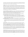
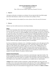
a) Frame Structure:
Information is sent around an Ethernet network in discreet messages known as frames. The frame structure
consists of the following fields:
Preamble - This consists of seven bytes, all of the form "10101010". This allows the receiver's clock to
be synchronized with the sender's.
Start Frame Delimiter - This is a single byte ("10101011") which is used to indicate the start of a
frame.
Destination Address - This is the address of the intended recipient of the frame. The addresses in 802.3
use globally unique hardwired 48 bit addresses.
Source Address - This is the address of the source, in the same form as above.
Length - This is the length of the data in the Ethernet frame, which can be anything from 0 to 1500
bytes.
Data - This is the information being sent by the frame.
Pad - 802.3 frame must be at least 64 bytes long, so if the data is shorter than 46 bytes, the pad field
must compensate. The reason for the minimum length lies with the collision detection mechanism. In
CSMA/CD the sender must wait at least two times the maximum propagation delay before it knows that
no collision has occurred. If a station sends a very short message, then it might release the ether without
knowing that the frame has been corrupted. 802.3 sets an upper limit on the propagation delay, and the
minimum frame size is set at the amount of data which can be sent in twice this figure.
CRC: Cyclic Redundancy Check to detect errors that occur during transmission (DIX version of FCS).
or FCS: Frame Check Sequence to detect errors that occur during transmission (802.3 version of CRC).
This 32 bit code has an algorithm applied to it which will give the same result as the other end of the
link, provided that the frame was transmitted successfully.
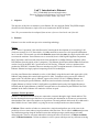
Figure 1 Structure of an Ethernet frame.
3
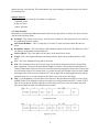
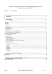
Ethernet vs. 802.3: Although the Ethernet and 802.3 standards are effectively the same thing, there are
some subtle differences between Ethernet II and 802.3. The IEEE 802.3 standard was part of a bigger
standard, 802. This contains a number of different network technologies, such as token ring, and token bus,
as well as Ethernet. These technologies are brought together by a layer on top of these MAC Layers called
Logical Link Control (LLC) as shown in the figure below. Ethernet II, however, does not use this LLC
layer.
Figure 2 Illustration of LLC layer.
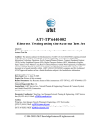
b) Physical Layer:
The Physical Layer is concerned with the low level electronic way in which the signals are transmitted. In
Ethernet, signals are transmitted using Manchester Phase Encoding (MPE) – see Appendix A. This
encoding is used to ensure that clocking data is sent along with the data, so that the sending and receiving
device clocks are in sync. The logic levels are transmitted along the medium using voltage levels of
±0.85V.
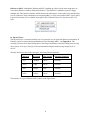
The table below lists some of the cable types utilized by Ethernet networks.
Cable type
Max speed
Max Length
Operating Frequency
CAT5
100 Mbps
100 m
100 MHz
CAT5e
1 Gbps
100 m
100 MHz
CAT6
10 Gbps
50 m
250 MHz
CAT6a
10 Gbps
100 m
500 MHz
The structure of a typical Ethernet cable is shown in the figure below.
4
Figure 3 Ethernet cable structure.
c) Media Access Control (MAC) Operation:
Ethernet is a CSMA/CD (Carrier Sense Multiple Access/Collision Detection) network. To send a frame, a
station on an 802.3 network first listens to check if the medium is busy. If it is, then, the station uses the 1persistent strategy, and transmits after only a short fixed delay (the inter-frame gap) after the medium
becomes idle. If there is no collision, then this message will be sent normally. If the device detects a
collision however, the frame transmission stops and the station sends a jamming signal to alert other
stations of the situation. The station then decides how long to wait before re-sending using a truncated
binary exponential backoff algorithm. The station waits for some multiple of 51.2us slots. The station first
waits for either 0 or 1 slots, then transmits. If there is another collision, then the station waits for 0,1,2 or 3
slots before transmitting. This continues with the station choosing to wait a random number of slots from 0
to 2^k - 1 if there have been k collisions in the current transmission, until k=10 where the number of slots
chosen from stops growing. After 16 continuous collisions, the MAC layer gives up and reports a failure to
the layer above.
Many companies offer Ethernet MAC (EMAC) Controllers as SW or HW cores.
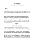
3. Open Systems Interconnection (OSI) Model
The Open Systems Interconnection (OSI) model is a prescription of characterizing and standardizing the
functions of a communications system in terms of abstraction layers. Similar communication functions are
grouped into logical layers. A layer serves the layer above it and is served by the layer below it.
5
Figure 4 Illustration of the 7 layers of the OSI model. An example.
A brief explanation of each of these seven layers follows:
7. Application layer: The top-most layer of the OSI model. The primary role of the application layer is that
it checks resource usability and synchronization with the remote partner. The application layer is the
closest to the end user, which means that both the OSI application layer and the user interact directly
with the software application.
6. Presentation layer: The function of this layer is very critical as it provides encryption services. Other
services apart from encryption include decryption, data compression, and decompression.
5. Session layer: The session layer controls the dialogues (connections) between computers. It establishes,
manages and terminates the connections between the local and remote application. It provides for fullduplex, half-duplex, or simplex operation, and establishes checkpointing, adjournment, termination, and
restart procedures. This layer also separates the data of different applications from each other.
4. Transport layer: The transport layer provides transparent transfer of data between end users, providing
reliable data transfer services to the upper layers. The transport layer controls the reliability of a given
link through flow control, segmentation/desegmentation, and error control. The transport layer is
responsible basically for segmentation and reassembly (S&R).The data from upper layer is combined
together and sent as a single data stream. The Transmission Control Protocol (TCP) and the User
Datagram Protocol (UDP) of the Internet Protocol Suite are commonly categorized as layer-4 protocols
within OSI.
3. Network layer: The network layer provides the functional and procedural means of transferring variable
length data sequences from a source host on one network to a destination host on a different network (in
contrast to the data link layer which connects hosts within the same network), while maintaining the
quality of service requested by the transport layer. This layer basically is used for routing. It tracks
location of devices. Data travels organized as packets - data packets and route-update packets.
2. Data Link Layer (DLL): The data link layer provides the functional and procedural means to transfer
data between network entities and to detect and possibly correct errors that may occur in the physical
layer. This layer is usually divided into 2 sublayers – 1) the upper one is LLC (Logical Link Control)
and the lower one is MAC (Medium Access Control). The DLL deals with the movement of data on
Local Area Networks (LANs). The data movement is in the form of frames and forwarded on the basis
of hardware address called the MAC address.
6
1. Physical layer: The physical layer defines electrical and physical specifications for devices. It defines the
relationship between a device and a transmission medium, such as a copper or fiber optical cable. This
includes the layout of pins, voltages, line impedance, cable specifications, signal timing, hubs,
repeaters, network adapters, etc. Data travels in form of digital signals, e.g., 01110001000. The real
transmission takes place here, i.e., traveling through a medium like cable, fiber optic, or air.
4. The Internet Protocol (a.k.a. TCP/IP Protocol)
The Internet Protocol suite is the set of communications protocols used for the Internet and similar
networks. It is generally the most popular protocol stack for wide area networks. It is commonly known as
TCP/IP, because of its most important protocols: Transmission Control Protocol (TCP) and Internet
Protocol (IP), which were the first networking protocols defined in this standard. It is also referred to as the
DoD model - due to the foundational influence of the ARPANET in the 1970s (operated by DARPA, an
agency of the United States Department of Defense).
TCP/IP provides end-to-end connectivity specifying how data should be formatted, addressed, transmitted,
routed and received at the destination. It has four abstraction layers (see figure below) which are used to
sort all Internet protocols according to the scope of networking involved. From lowest to highest, the layers
are:
1. Link layer: contains communication technologies for a local network.
2. Internet layer (IP): connects local networks, thus establishing internetworking.
3. Transport layer: handles host-to-host communication.
4. Application layer: contains all protocols for specific data communications services on a process-toprocess level. It focuses more on network services, APIs, utilities, and operating system environments.
For example, HTTP specifies the web browser communication with a web server. See Appendix B for
more info.
Figure 5 Comparison of TCP/IP and OSI layer stacks.
Note 1: Sometimes, people mix or are not aware of the meaning and differences between Ethernet and
TCP/IP. Generally speaking, they are different levels or layers of a network. Ethernet covers the physical
medium plus some low level things like message collision detection. TCP/IP worries about getting a
message to where it is going.
TCP/IP is usually found on Ethernet based networks, but it can be used on other networks as well. Also, you
can have Ethernet without TCP/IP, and in fact a lot of proprietary industrial networks do exactly that. In
addition, you can also run TCP/IP in parallel with other things like UDP on the same Ethernet connection.
7
Note 2: In the seven-layer OSI model of computer networking, “packet” strictly refers to a data unit at
layer 3, the Network Layer. At this layer, a packet is also commonly called a “datagram”. The correct term
for a data unit at the Data Link Layer - Layer 2 of the seven-layer OSI model - is a “frame”, and at Layer
4, the Transport Layer, the correct term is a “segment”. Hence, e.g., a TCP segment is carried in one or
more IP Layer datagrams (or packets), which are each carried in one or more Ethernet frames - though
the mapping of TCP, IP, and Ethernet, to the layers of the OSI model is not exact (as we’ll discuss in the
next section).
Some prefer to refer to all these simply as (network) packets. Network packets are described like Russian
dolls (a.k.a. Matroishka). An IP-packet resides within an Ethernet-packet. A TCP-packet resides within an
IP-packet. A HTTP-packet resides within a TCP-packet. See figure below for an illustration of this point.
Figure 6 TCP packet (or segment) vs. IP datagram (or packet) vs. Ethernet packet (or frame).
A network packet is nothing more than a chunk of data that an application wants to deliver to another
system on the network. This chunk of data has information added to the front and back that contains
instructions for where the data needs to go and what the destination system should do with it once it arrives.
The addition of this routing and usage information is called encapsulation.
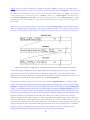
The figure below illustrates the process. We start with a chunk of application data, to which we add a
header. We take that data (application data plus application header) and package it up as a series of TCP
segments by adding TCP headers. We then add an IP header to each TCP segment, making IP datagram.
Finally, we add Ethernet headers and trailers to the IP datagrams, making an Ethernet frame that we can
send over the wire. Each layer has its own function: TCP (the transport layer) makes sure data gets from
point A to point B reliably and in order; IP (the network layer) handles routing, based on IP addresses and
should be familiar to you; and Ethernet (the link layer) adds low-level MAC (media access control)
addresses that specify actual physical devices. It's also important to note that there are several choices at
each layer of the model: at the transport layer, you can see either TCP, UDP, or ICMP. Each layer of the
network stack is unaware of the layers above and below. The information coming from the layers above are
simply treated as data to be encapsulated. Many application protocols can be packed into TCP. When the
packet is received at its final destination, the same process is repeated in reverse. The packet is deencapsulated and the headers stripped off when it is received by the intended target.
8
Figure 7 Illustration of encapsulation.
5. The Internet
The Internet is a global system of interconnected computer networks that use the standard Internet Protocol
suite (TCP/IP) to serve billions of users worldwide. It is a network of networks that consists of millions of
private, public, academic, business, and government networks, of local to global scope, that are linked by a
broad array of electronic, wireless and optical networking technologies. The Internet carries an extensive
range of information resources and services, such as the inter-linked hypertext documents of the World
Wide Web (WWW) and the infrastructure to support email.
A simplified architecture of the Internet network is shown in the figure below.
Figure 8 Simplified Internet architecture.
9
Another view of the Internet, that illustrates various components at different hierarchy levels, is shown in
figure below.
Figure 9 Illustration of the hierarchy of the Internet.
6. Ethernet Block of LPC1768
The Ethernet block contains a full featured 10 Mbps or 100 Mbps Ethernet MAC (Media Access
Controller) designed to provide optimized performance through the use of DMA hardware acceleration.
Features include a generous suite of control registers, half or full duplex operation, flow control, control
frames, hardware acceleration for transmit retry, receive packet filtering and wake-up on LAN activity.
Automatic frame transmission and reception with Scatter-Gather DMA off-loads many operations from the
CPU.
The Ethernet block is an AHB master that drives the AHB bus matrix. Through the matrix, it has access to
all on-chip RAM memories. A recommended use of RAM by the Ethernet is to use one of the RAM blocks
exclusively for Ethernet traffic. That RAM would then be accessed only by the Ethernet and the CPU, and
possibly the GPDMA, giving maximum bandwidth to the Ethernet function.
The Ethernet block interfaces between an off-chip Ethernet PHY using the RMII (Reduced Media
Independent Interface) protocol and the on-chip MIIM (Media Independent Interface Management) serial
bus, also referred to as MDIO (Management Data Input/Output).
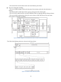
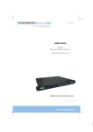
The block diagram of the Ethernet block - shown in the figure below - consists of:
The host registers module containing the registers in the software view and handling AHB accesses to
the Ethernet block. The host registers connect to the transmit and receive data path as well as the MAC.
The DMA to AHB interface. This provides an AHB master connection that allows the Ethernet block to
access on-chip SRAM for reading of descriptors, writing of status, and reading and writing data buffers.
The Ethernet MAC, which interfaces to the off-chip PHY via an RMII interface.
The transmit data path, including:
– The transmit DMA manager which reads descriptors and data from memory and writes status to
memory.
– The transmit retry module handling Ethernet retry and abort situations.
10
– The transmit flow control module which can insert Ethernet pause frames.
The receive data path, including:
– The receive DMA manager which reads descriptors from memory and writes data and status to
memory.
– The Ethernet MAC which detects frame types by parsing part of the frame header.
– The receive filter which can filter out certain Ethernet frames by applying different filtering schemes.
– The receive buffer implementing a delay for receive frames to allow the filter to filter out certain
frames before storing them to memory.
Figure 10 Block diagram of the Ethernet block of LPC17xx microcontrollers.
The fields of the Ethernet packet are as shown in the figure below.
Figure 11 Fields of the Ethernet packet.
11
7. Example 1: EasyWEB
This is the EasyWEB example that comes as part of the code bundle from NXP. You can also find it inside
the downloadable archive with the files of this lab.
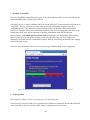
The EMAC project is a simple embedded web server for the NXP LPC17xx microcontrollers also known as
“EasyWEB”. This tiny web server was taken from the “Design & Elektronik” magazine extra issue
“Embedded Internet”. This software was adapted to work with a Keil MCB1700 board and the ARM
RealView C-Compiler with as few modifications as possible. The served web page shows the value of one
analog input (AN2) which can be controlled via the blue potentiometer on the MCB1700 board.
Please read the 1_code.bundle.lpc17xx.keil.emac.pdf file (included in the downloadable archive for this
lab) to see how to set-up and run this example (use the CAT 5E cable from your TA). Compile, and
download to the board. Observe operation and comment. When up and running you should see the webpage
shown in the figure below.
Take some time and read the source code in order to get a good understanding of what’s happening.
Figure 12 Webpage that shows the value of the ADC value of the MCB1700 board.
8. Lab assignment
This is optional. If done correctly, you may get up to 2% of the final grade.
Create a new uVision project and write a program that uses Ethernet to connect two boards and transmit the
value of the ADC from one board to the other, where it is displayed on the LCD screen.
12
9. Credits and references
[1]
--Ethernet Introduction, Ross MCIlroy, 2004; http://www.dcs.gla.ac.uk/~ross/Ethernet/index.htm
--Data Network Resource, Rhys Haden, 2013; http://www.rhyshaden.com/eth_intr.htm
--OSI Model, Wikipedia entry; http://en.wikipedia.org/wiki/OSI_model
--Internet Protocol, Wikipedia entry; http://en.wikipedia.org/wiki/TCP/IP_model
--How the Application Layer Works; http://learn-networking.com/tcp-ip/how-the-application-layer-works
--Introduction to Internet Architecture and Institutions , Ethan Zuckerman and Andrew McLaughlin, 2003;
http://cyber.law.harvard.edu/digitaldemocracy/internetarchitecture.html
--Internet: "The Big Picture"; http://navigators.com/internet_architecture.html
--Internet Technical Resources; http://www.cs.columbia.edu/~hgs/internet/
--Internet; Wikipedia entry; http://en.wikipedia.org/wiki/Internet
[2] LPC17xx user manual, 2010; http://www.nxp.com/documents/user_manual/UM10360.pdf
APPENDIX A: Manchester Phase Encoding (MPE)
802.3 Ethernet uses Manchester Phase Encoding (MPE). A data bit '1' from the level-encoded signal (i.e.,
that from the digital circuitry in the host machine sending data) is represented by a full cycle of the inverted
signal from the master clock which matches with the '0' to '1' rise of the phase-encoded signal (linked to the
phase of the carrier signal which goes out on the wire). i.e., -V in the first half of the signal and +V in the
second half.
The data bit '0' from the level-encoded signal is represented by a full normal cycle of the master clock
which gives the '1' to '0' fall of the phase-encoded signal. i.e., +V in the first half of the signal and -V in the
second half.
The following diagram shows graphically how MPE operates. The example at the bottom of the diagram
indicates how the digital bit stream 10110 is encoded.
Figure 13 Illustration of MPE operation.
13
A transition in the middle of each bit makes it possible to synchronize the sender and receiver. At any
instant the ether can be in one of three states: transmitting a 0 bit (-0.85v), transmitting a 1 bit (0.85v) or
idle (0 volts). Having a normal clock signal as well as an inverted clock signal leads to regular transitions
which means that synchronization of clocks is easily achieved even if there are a series of '0's or '1's. This
results in highly reliable data transmission. The master clock speed for Manchester encoding always
matches the data speed and this determines the carrier signal frequency, so for 10Mbps Ethernet the carrier
is 10MHz.
APPENDIX B: How the Application Layer of TCP/IP layer stack model works
One may ask why an Application Layer is needed for TCP/IP, since the Transport Layer handles a lot of
interfacing between network and applications. While this is true, the Application Layer focuses more on
network services, APIs, utilities, and operating system environments.
By breaking the TCP/IP Application Layer into three separate layers, we can better understand what
responsibilities the Application Layer actually has.
The OSI Equivalent of the TCP/IP Application Layer:
1. Application Layer - The seventh OSI model layer (which shouldn’t be confused with the TCP/IP stack’s
Application Layer). It supports network access, as well as provides services for user applications.
2. Presentation Layer - The Sixth OSI model layer is the Presentation Layer. It translates data into a
format that can be read by many platforms. With all the different operating systems, programs, and
protocols floating around, this is a good feature to have. It also has support for security encryption and
data compression.
3. Session Layer - The fifth layer of the OSI model is the Session Layer. It manages communication
between applications on a network, and is usually used particularly for streaming media or using web
conferencing.
To better see the concepts of the Application Layer, let’s take a look at a few examples of the Application
Layer in action:
Application Layer APIs
A good example of an API is DirectX. If you’ve ever run a multimedia application and used Windows at
the same time, odds are you have come into contact with DirectX. DirectX is made up of many different
components that allow programmers to create multimedia applications (such as video games).
There are many types of APIs. You may have heard of NetBIOS, Winsock, or WinAPI among others. The
world of APIs has also extended to web services. You may have heard of a Google API, for instance. In this
case Google allows developers to use its internal functions, yet also keeps Google’s internal code safe.
Network Services
The Application Layer handles network services; most notably file and printing, name resolution, and
redirector services.
14
Name resolution is the process of mapping an IP address to a human-readable name. You may be familiar
with the name Google more so than the IP address of Google. Without name resolution, we would have to
remember four octets of numbers for each website we wanted to visit…
A redirector, otherwise known as a requester, is a service that is largely taken for granted. It is a handy
service that looks at requests a user may make: if it can be fulfilled locally, it is done so. If the request
requires a redirection to another computer, then the request is forwarded onto another machine. This enables
users to access network resources just like they were an integral part of the local system. A user could
browse files on another computer just like they were located on the local computer.
Lastly we have file and print services. If a computer needs to access a file server or a printer, these services
will allow the computer to do so. While fairly self-explanatory it’s worth reviewing...
Network Utilities
This is where most people have experience - within the network utilities section of the Application Layer.
Every time you use a Ping, Arp, or Traceroute command, you are taking full advantage of the Application
Layer.
It’s quite convenient that the Application Layer is located on the top of the TCP/IP stack. We can send a
Ping and, if successful, can verify that the TCP/IP stack is successfully functioning. It’s a good idea to
commit each utility to memory, as they are very useful for maintaining, configuring, and troubleshooting
networks.
Listed below are seven of the most used utilities.
1. ARP - Arp stands for Address Resolution Protocol. It is used to map an IP address to a physical address
found on your NIC card. Using this command can tell us what physical address belongs to which IP
address.
2. Netstat - Netstat is a tool that displays local and remote connections to the computer. It displays IP
addresses, ports, protocol being used, and the status of the connection.
3. Ping - Ping is a simple diagnostic tool that can check for connectivity between two points on a network.
It is one of the most used TCP/IP utilities when setting up a network or changing network settings.
4. TraceRT - Tracert, or traceroute, is a command that shows the path that packets of data take while being
sent. It’s handy for checking to see where a possible network failure lies, or even for ensuring that data
packets are taking the fastest route possible on a network.
5. FTP/TFTP - FTP and TFTP are both used for transferring files. It is important to note that FTP is a TCP
utility, while TFTP is a UDP utility. TFTP tends to be less secure than FTP, and is generally only used
for transferring non-confidential files over a network when speed is concerned.
6. Hostname - Hostname is a simple command that displays the hostname of the current computer: simple
yet effective.
7. Whois - Whois information is just like an online phonebook. It shows the contact information for owners
of a particular domain. By using a Whois search, you will find that Google is based in California .
APPENDIX C: Key Features of TCP/IP
Five of the most important features of TCP/IP are:
a) Application support
15
b)
c)
d)
e)
Error and flow control
Logical Addressing
Routing
Name resolution
a) Application Support
Assume you are multitasking - you are uploading files to your website, sending an email, streaming music,
and watching video all at the same time. How does the computer know where to send each packet of data if
multiple applications are running? We sure wouldn’t want to use our email program to watch video, and
vice versa!
This problem is addressed by using channels called ports. These numbered ports each correspond to a
certain action. For example, the email is likely using port 25 for operation. Files you upload to your website
use the FTP port, which is usually port 20 and 21. Browsing a webpage uses a specific port - the HTTP port
80.
In total, there are 65,535 ports for controlling the flow of information.
b) Error and Flow Control
TCP/IP is considered a connection-oriented protocol suite. This means that if data isn’t received correctly, a
request to resend the data is made. This is compared to User Datagram Protocol (UDP), which is
connectionless. UDP is a suite of protocols just like TCP/IP, with a few notable differences. UDP is great
for broadcasting data - such as streaming radio music. If part of the data was lost, we wouldn’t want to go
back and retrieve it - it would waste bandwidth, and would create collisions or noise in our signal. With
UDP, the lost data might be represented as a silent spot.
c) Logical Addressing
Most computers today come standard with Network Interface Cards (NICs). These cards are the actual
hardware used to communicate to other computers. Each card has a unique physical address that is set at
the factory, and can’t be changed. Essentially this is an identifier for the computer it is installed on.
Networks rely on the physical address of a computer for data delivery, but we have a problem. The NIC
card is constantly looking for transmissions that are addressed to it - what if the network was very large in
size? To put it into perspective, imagine your computer looking at every single bit of data on the internet to
see if any of the millions of data packets are addressed to it.
This is where logical addressing comes in. You are probably more familiar with the term IP address,
however. These IP addresses can be subnetted on a network to divide a large network into tiny pieces.
Instead of looking at every bit of data on the internet, logical addressing allows for computers to just look at
data on a home network or subnet.
d) Routing
A router is a device used to read logical addressing information, and to direct the data to the appropriate
destination. Routers are commonly used to separate networks into portions - this greatly reduces network
traffic if done correctly.
16
TCP/IP includes protocols that tell routers how to find a path through the network. This is a vital feature of
the TCP/IP suite that enables massive LAN connections to be created.
e) Name Resolution
Finally, we have name resolution. If you wanted to conduct a search on the internet, you would probably
just type Google’s URL into your address bar. What you probably didn’t know is that you aren’t necessarily
connecting to “google.com”, but rather an IP address. Instead of having to remember an IP address, name
resolution allows you to remember Google’s name.
It might not be so bad if IP addresses were not so lengthy in size. Which is easier to remember
http://74.125.224.72/ or google? This handy service is accomplished on name servers, which are just
computers that store tables that translate domain names to and from IP addresses.
17