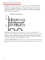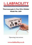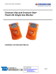
1
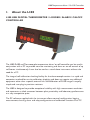
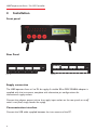
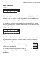
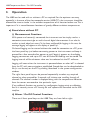
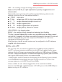
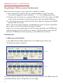
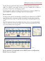
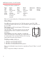
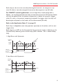
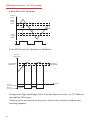
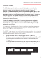
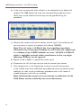
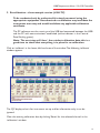
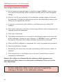
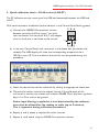
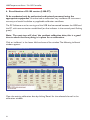
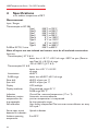
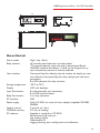
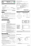
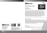
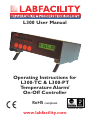
L300 User Manual
Operating Instructions for
L300-TC & L300-PT
Temperature Alarm/
On-Off Controller
RoHS compliant
Certificate No. 4746
www.labfacility.com
L300 Temperature Alarm / On-Off Controller
Contents
1. About the L300 . . . . . . . . . . . . . . . . . . . . . . . . . . . . . . . . . . . . . . . . . . . . . . . . . . . . . . . . . . . . . . . . . . . 3
2. Installation. . . . . . . . . . . . . . . . . . . . . . . . . . . . . . . . . . . . . . . . . . . . . . . . . . . . . . . . . . . . . . . . . . . . . . . 4-5
Front panel . . . . . . . . . . . . . . . . . . . . . . . . . . . . . . . . . . . . . . . . . . . . . . . . . . . . . . . . . . . . . . . . . . . . . . . . . . 4
Rear panel . . . . . . . . . . . . . . . . . . . . . . . . . . . . . . . . . . . . . . . . . . . . . . . . . . . . . . . . . . . . . . . . . . . . . . . . . . . 4
Supply connection . . . . . . . . . . . . . . . . . . . . . . . . . . . . . . . . . . . . . . . . . . . . . . . . . . . . . . . . . . . . . . . . . . . 4
Communication interface . . . . . . . . . . . . . . . . . . . . . . . . . . . . . . . . . . . . . . . . . . . . . . . . . . . . . . . . . . . . 4
Sensor connections . . . . . . . . . . . . . . . . . . . . . . . . . . . . . . . . . . . . . . . . . . . . . . . . . . . . . . . . . . . . . . . . . . 5
Relay connections . . . . . . . . . . . . . . . . . . . . . . . . . . . . . . . . . . . . . . . . . . . . . . . . . . . . . . . . . . . . . . . . . . . . .
3. Operation . . . . . . . . . . . . . . . . . . . . . . . . . . . . . . . . . . . . . . . . . . . . . . . . . . . . . . . . . . . . . . . . . . . . . . 6-22
a) Stand alone. . . . . . . . . . . . . . . . . . . . . . . . . . . . . . . . . . . . . . . . . . . . . . . . . . . . . . . . . . . . . . . . . . . . . . . 6
Measurement Functions
To read sensor temperatures directly . . . . . . . . . . . . . . . . . . . . . . . . . . . . . . . . . . . . . . . . . . . . 6
To scroll through all channels . . . . . . . . . . . . . . . . . . . . . . . . . . . . . . . . . . . . . . . . . . . . . . . . . . . . 6
Alarm /On-Off Control Functions . . . . . . . . . . . . . . . . . . . . . . . . . . . . . . . . . . . . . . . . . . . . . . . . . . 6
b) Use with a PC. . . . . . . . . . . . . . . . . . . . . . . . . . . . . . . . . . . . . . . . . . . . . . . . . . . . . . . . . . . . . . . . . . . . 7
Install the software . . . . . . . . . . . . . . . . . . . . . . . . . . . . . . . . . . . . . . . . . . . . . . . . . . . . . . . . . . . . . . . 7
Control panel . . . . . . . . . . . . . . . . . . . . . . . . . . . . . . . . . . . . . . . . . . . . . . . . . . . . . . . . . . . . . . . . . . . . 8
Measurement Functions . . . . . . . . . . . . . . . . . . . . . . . . . . . . . . . . . . . . . . . . . . . . . . . . . . . . . . 8
Sensor type selection . . . . . . . . . . . . . . . . . . . . . . . . . . . . . . . . . . . . . . . . . . . . . . . . . . . . . . . . . . . . 9
System Configuration . . . . . . . . . . . . . . . . . . . . . . . . . . . . . . . . . . . . . . . . . . . . . . . . . . . . . . . . . . . 10
Comms port . . . . . . . . . . . . . . . . . . . . . . . . . . . . . . . . . . . . . . . . . . . . . . . . . . . . . . . . . . . . . . . 10
L300 settings . . . . . . . . . . . . . . . . . . . . . . . . . . . . . . . . . . . . . . . . . . . . . . . . . . . . . . . . . . . . . . . 10
Chart recorder display . . . . . . . . . . . . . . . . . . . . . . . . . . . . . . . . . . . . . . . . . . . . . . . . . . . . . . . . . . 11
PC logging . . . . . . . . . . . . . . . . . . . . . . . . . . . . . . . . . . . . . . . . . . . . . . . . . . . . . . . . . . . . . . . . . . . . . . 11
L300 on-board logging . . . . . . . . . . . . . . . . . . . . . . . . . . . . . . . . . . . . . . . . . . . . . . . . . . . . . . . . . . 12
Alarm / On-Off Control Functions
Calibration checking; L300-TC, thermocouple version . . . . . . . . . . . . . . . . . . . . . . . . . 17
Re-calibration;
L300-TC, thermocouple version . . . . . . . . . . . . . . . . . . . . . . . . . 19
Calibration checking; L300-PT, Pt100 version . . . . . . . . . . . . . . . . . . . . . . . . . . . . . . . . . . . 21
Re-calibration;
L300-PT, Pt100 version . . . . . . . . . . . . . . . . . . . . . . . . . . . . . . . . . . . 22
4. Specifications . . . . . . . . . . . . . . . . . . . . . . . . . . . . . . . . . . . . . . . . . . . . . . . . . . . . . . . . . . . . . . . . . 24-26
5. Application notes . . . . . . . . . . . . . . . . . . . . . . . . . . . . . . . . . . . . . . . . . . . . . . . . . . . . . . . . . . . . 27-30
Temperature measurements made with the L300 are in accordance with
IEC584 & IEC751, ITS90 refers.
Information in this publication may be subject to change. E & O E.
2
L300 Temperature Alarm / On-Off Controller
1.
About the L300
L300 USB DIGITAL THERMOMETER / LOGGER / ALARM / ON-OFF
CONTROLLER
The L300 Pt100 and Thermocouple temperature alarm/ on-off controller can be used in
conjunction with a PC to provide accurate monitoring and alarm or on-off control of up
to 8 zones simultaneously. It can also be used as a stand-alone instrument without the
need for a PC.
The integral, self-calibration checking facility for the thermocouple version is a rapid and
convenient method for on-site calibration checking and does not require any additional
equipment other than a special, external link. Self-calibration of Pt100 ranges is equally
simple and uses plug-in precision resistors.
The L300 is designed to provide exceptional stability with high measurement resolution
and represents an ideal crossover between plant practicality and laboratory performance
at a very competitive price.
The PC software supplied with the instrument allows control, configuration, logging,
measurement, charting, alarm and relay configuration and calibration functions via a PC.
3
L300 Temperature Alarm / On-Off Controller
2.
Installation
Front panel
Rear Panel
L300-TC
L300-PT
Supply connection
The L300 operates from a 6 to 9V dc supply. A suitable 90 to 250V 50/60Hz adaptor is
supplied with the instrument, complete with alternative pin configurations for
international supply outlets.
Connect the adaptor output jack to the supply input socket on the rear panel; an on-off
switch is not fitted, simply connect the supply.
Communication interface
Connect the USB cable supplied between the instrument and the PC.
4
L300 Temperature Alarm / On-Off Controller
Sensor connections
L300-TC, thermocouple inputs
L300-TC
Only the appropriate, miniature (flat pin) , colour coded and polarised thermocouple
plug can be used for each input. Any type of thermocouple (eg K,N,T etc) can be
connected to any input but each must be terminated in the correct type of plug, colour
coded to suit the attached thermocouple type.The particular thermocouple type must
be selected for each channel via the PC software.
Any unused input channels are simply ignored; in such cases, the appropriate channel
display will indicate an upscale (high value) reading on both the instrument front panel
and in the PC control panel.
L300-PT, Pt100 inputs
L300-PT
The L300 uses a 3-wire configuration for each input and connections are made to
‘plug-in’ terminal blocks. If a 4-wire probe is used, the 4th wire (either red or white) is
left unconnected and , if necessary, insulated to avoid any cross-connection contact.
If a 2 wire connection is used, connect the red and white wires as shown in the diagram
and link terminals C & B.
C B A
Sensor connections can be made with the terminal block in-situ
(plugged in to the rear panel) or the block can be unplugged
from the instrument if preferred.
Any unused inputs are simply ignored; in such cases, the
appropriate channel display will indicate an upscale (high value)
reading on both the instrument front panel and in the PC
control panel.
Red
White
Red
5
L300 Temperature Alarm / On-Off Controller
3.
Operation
The L300 can be used with or without a PC as required. For the optimum accuracy,
especially in the case of the thermocouple version (L300-TC), the instrument should be
allowed due time to ‘settle’ in the ambient temperature of its location before use.This is
important if it is moved between locations of greatly different ambient temperatures.
a) Stand alone without PC
i) Measurement Functions
With power and sensor(s) connected, the instrument can be simply used as a
convenient, accurate single or multi-channel digital thermometer. It can also be
used on a stand alone basis even if it has been configured for logging; in this case, the
message ‘logging’ will appear on the display at ‘power up’.
On-board logging can be started without the need for connection to a PC; press
the front panel key just before connecting power to the instrument and keep it
pressed for a few seconds after power-up until ‘logging’ appears on the display.
Logging commences and up to 512 sets of 8 channel readings can be stored.The
logging interval will be whatever value was last selected via the PC software.
Logging will cease when the instrument is powered-down or when ‘off’ is selected
from the PC with communications established. Stored data can be downloaded to
file (in .csv format) on the PC by clicking ‘download’ in the system configuration
window.
The right front panel key can be pressed sequentially to select any required
channel or, when pressed for 3 seconds, will initiate auto scrolling through all
channels.The channel number is displayed along with the temperature indication
from the sensor connected to that particular input.
If any additional functions are required, e.g. configuration, logging set-up or calibration,
then it is necessary to use a PC running the user software and connected via the USB
interface.
ii) Alarm / On-Off Control Functions
There are 4 front panel keys on the L300.They are, from left to right:
LEFT / UP / DOWN / RIGHT
6
L300 Temperature Alarm / On-Off Controller
LEFT – for scrolling through the configuration parameters.
Refer to P14, 15 & 16 for a full explanation of relay configurations and
alarm modes.
Sequentially pressing this key will scroll through the following selections, for
example, assuming that we have selected channel 1:
1_1234.5 – input value
1T High
– output type: Off, On, High, Low and Band
1C
5 – output associated to input channel to 5
1V 1234 – output triggered value
1B
10 – output triggered band or hysteresis
1P Norm – output polarity: Normal or Inverse
UP & DOWN – for changing values
RIGHT – for scrolling through channels and selecting Auto Scrolling
This key is pressed sequentially to select any required channel or, when pressed
and held for 3 seconds, will initiate auto-scrolling through all channels.The channel
number is displayed along with the temperature indication from the sensor
connected to that particular input.
All of the alarm /on-off control functions can be configured in the PC software
supplied with the instrument.
b) Use with a PC
For use with a PC, the software supplied with the L300 must be installed on
the PC* and communication established via the USB lead supplied (online, green
indicator flashing). System requirements for installing the L300 software:Windows
XP with at least one USB port. All WINDOWS operating systems prior to XP do
not support USB natively and are not recommended.
* Ideally, English should be selected as the language for the Operating System (selected
via the WINDOWS Control Panel). Alternative language selection can result in error
messages appearing in the L300 Control Panel window.
Create a folder for the software; logged data will be saved to this folder.
Connect the USB cable supplied between a PC USB port and the L300 USB port
before running the PC software.
7
L300 Temperature Alarm / On-Off Controller
Using Multiple L300 Instruments Simultaneously
More than one instrument can be used with a single PC as follows:
i) Load a separate PC software file into a separate folder on the PC for each
instrument ( suggestion; name the folders ...1, ...2 etc to differentiate them).
ii) Connect each instrument via a separate USB port on the PC; the number of L300s
which can be connected is limited only by the number of available USB ports.
iii) In the configuration panel of each Control Panel, select the appropriate COMMS
port for each instrument.
Note 1. Ensure that communication is established with each instrument connected;
this is shown in the Control Panel by the green indicator.
Note 2. On instrument power-down, the PC will only remember the COMMS port
used for the last instrument which is shut down. It will be necessary to re-connect
the other COMMS ports when powering –up the additional instruments.
Control panel
i) Measurement Functions
In the L300 software folder, double click on the ‘L300 Control Panel’ icon.
The following window is opened:
L300-TC
L300-PT
The online indicator flashes green when communications between the L300 and the PC
are established (see System configuration on next page).
8
L300 Temperature Alarm / On-Off Controller
The PC software automatically opens the Control Panel appropriate to either the
L300-TC or L300-PT as connected. To reset at any time, if needed, click on ‘Refresh’ in
the System Configuration (config/logging) window.
The eight channels readout will display either temperature or millivolts (L300-TC) or
Ohms (L300-PT) is selected in the ‘display’ box on the control panel.
Sensor selection
To find out which type of thermocouple is selected for each channel with the L300-TC,
simply double click on the channel readout; the selection can be simply changed by
clicking on the arrow in the ‘T/C type’ box and clicking on the desired type and then
‘send’.
Note:The ‘calibration’ box in the window, may show y =mx +c with pre-determined
values for m&c which are offset correction values allocated during production.These
must not be altered and can be ignored.
L300-TC
L300-PT
Sensor selection is not applicable to the L300-PT which is configured for
Pt100, 3 wire on all inputs.
9
L300 Temperature Alarm / On-Off Controller
System configuration:
Click on ‘configure/logging’ in the lower, left-hand corner of the window; the following
‘system configuration’ window is opened:
In this window, the Comms Port is selected and instrument settings are made.
Comms Port – Select the required port if this is not done automatically.
The online indicator flashes green when communications between the L300 and the PC
are established.
L300 settings
a) The L300 internal clock date & time are set to user defined values or PC clock
if ‘use PC Time’ is checked. The internal clock can be set by the user; PC or Internet
date & time can be set in the L300 internal clock by checking the ‘PC time’ box &
clicking ‘Send’, unchecking ‘PC time’ & clicking ‘Refresh’.
b) Auto Scan interval can be entered (2 to 10 seconds) and Autoscan switched on
or off.
c) °C or °F are selected.
d) Instrument button ‘beep’ can be selected or switched off.When settings are
completed, click ‘send’ and close the system configuration window. Changes to
settings can be made at any time.
10
L300 Temperature Alarm / On-Off Controller
Chart recorder display
For a chart recorder (analogue) display of all 8 channels, click on ‘chart’; the chart
recorder can be opened and closed as required.The default chart indicates all 8 channels
(regardless of the presence or absence of input connections, to any channel) and
operates ‘Auto’ scaling to determine the values on the X and Y axes.
The user can select any desired channels via the tick boxes under ‘channel’, the display of
2D or 3D Style by clicking on the appropriate circle and can select ‘Auto’ (variable) or
‘fixed’ scaling (fixed at values when ‘chart’ is selected).
The chart as displayed can be saved (in wmf format) by clicking ‘save’ to the left of the
chart.The file will be saved in the same folder as that in which the L300 software resides.
Logging
Logging can be carried out on one of two bases;
c) Real-time PC logging is started by clicking ‘Start’ in the control panel at any time, and
stopped by clicking ‘Stop’. Readings are saved in Notepad in ‘.csv’ format, in the same
folder as that in which L300 software resides.
The value of the display on the main window will be logged on the PC.This could be
temperature millivolts or resistance depending on the display setting in the main window.
11
L300 Temperature Alarm / On-Off Controller
d) L300 on-board logging is set up by clicking ‘Configure/logging’ in the control panel.
The following ‘logging control’ window is opened.
The logging interval for each chanel is set up (common) and sent to the instrument by
clicking ‘send’.
Logging is started by selecting ‘on’ in the ‘status’ box and clicking ‘send’. It is stopped by
selecting ‘off’ and clicking ‘send’.
Logged readings are downloaded to file in ‘.csv’ format in the PC by clicking ‘download’.
Downloading takes approximately 2.5 minutes; status is indicated in the window.The file
will be created in the same folder as used for the PC software.
The PC connection is not required during logging, only when configuring the logging regime.
Alternatively, logging will commence immediately when the front panel key is
pressed at the same time as the instrument is powered up. Logging will cease
when the instrument is powered down.
The L300 can be used ‘manually’ during logging, ie. channels can be selected
individually (or auto-scanned) via the front panel key for temperature readings.
When the on-board, logged values memory is full (512 sets of 8 readings),
those readings stored first will be overwritten by new values.
12
L300 Temperature Alarm / On-Off Controller
ii) Alarm / On-Off Control Functions
Open the Control Panel window as described in 3b ‘Use with a PC’ Control Panel.
Click on ‘Configure / Logging’. In the lower, left-hand corner of the window; the
following ‘System Configuration’ window is opened:
Output Channels Configuration
Eight output relays are available and they can be configured to suit any application
according to selection options in the table to the right of the ‘System Configuration’
window.
Select instrument ‘Read’ to enable configuration (this shows settings currently stored
in the instrument).
The cells to the right of the Output column are selected by clicking on the required
cell; double click on the selected cell to edit the setting (selected from drop down
options). Right click to read or write 1 channel.
When the required configuration is completed, click instrument ‘write’ to send all of
the data to the instrument. Settings for individual rows can be sent by right clicking
on the output ‘cell’ and clicking ‘write’ in the drop down box.
Clicking ‘Read at any time will show the relay configuration currently selected;
individual output configurations can be read by right clicking on the output ‘cell’ and
clicking ‘read’ in the drop down box.
The configuration can be saved to file or loaded from file via the ‘File’ panel.
13
L300 Temperature Alarm / On-Off Controller
Configuration options available are:
Type
Input
Value
Band
Hysteresis
Polarity
OFF
ON
HIGH
LOW
BAND
Select
input channel
1 to 8
(allocates
input channel
to output
channel)
Enter
trigger
(set point)
value
Enter
band value
if band
selected in
‘type’
column
Enter
value
Normal
inverted
Refer to the section below for a full description of each of these options.
Alarm Relays
The L300 has 8 output relays, each has 3 Volt-free contacts rated 10A / 250V.
The Volt-free contacts allow the user to wire whichever signals are required, a.c or
d.c up to 250V.
The contacts are NO (normally open), COM (common),
NC
NO
NC (normally closed).
‘Normally Open’ is the contact position with the relay deenergised (& when there is no power connected to the
instrument).
The Outputs can be used as required in a closed loop
system (on-off control) or open loop (e.g. to apply power to
or remove power from any external device such as warning
lamps, external contacts, alarm klaxons).
COM
The Alarm modes available are:
1. High Alarm with adjustable hysteresis
2. Low Alarm with adjustable hysteresis
3. Band Alarm with adjustable band and hysteresis.
Relays can be allocated to input channels as required, e.g: Channel 1 Relay 1 as on-off
control.
Relay 2 as high alarm & Relay 3 as low alarm.
14
L300 Temperature Alarm / On-Off Controller
Each relay can be set to be normally de-energised (normal) , to energise on trip
(non fail-safe) or normally energised (inverse) to de-energise on trip (fail-safe).
For ON/OFF control applications, use the High Alarm mode configured as
follows: set the designated control relay to Inverted and use the NO contact. Power
will only be applied when the process temperature is below the set-point (trigger
value). As soon as the process temperature exceeds the trigger value, the relay will
de-energise and power to the heater will be disconnected (fail-safe).
Refer to the Application Note 5.1 on page 26
Each relay is independent; one relay operates separately to the others, with its own
trigger value.
Each relay has an LED on the front panel of the instrument (and an indicator on the
Control Panel) indicating status of that relay (LED/ indicator ON = relevant Relay
ON).
1. High Alarm with Hysteresis
p
Process
Temp
s
es
m
Te
oc
Pr
Trigger
Value
Hysteresis
Time
Relay on
(normal mode)
1
ALARM
ALARM
Relay off
(normal mode)
2. Low Alarm with Hysteresis
Process
Temp
p
em
sT
s
ce
Pro
Trigger
Value
Hysteresis
Time
Relay on
(normal mode)
1
ALARM
ALARM
Relay off
(normal mode)
15
L300 Temperature Alarm / On-Off Controller
3. Band Alarm with Hysteresis
Process
Temp
Upper
Trigger
Value
Hysteresis
Pr
es
oc
Band
p
em
sT
Time
Hysteresis
Lower
Trigger
Value
1
ALARM
ALARM
4. On-Off Control with Hysteresis as Deadband
Process
Temperature
Hysteresis
(Deadband)
Pr
o
ce
ss
Te
m
p
Trigger Value
(Set Point)
Relay on
(inverted mode)
Relay off
(inverted mode)
Time
1
Power
applied
Power
applied
Configuration: High mode/Trigger Value = Set Point/Hystersis value 1 or 2°C*/Polarity
inverted/Use NO contact.
*Observe warm-up & setting time; hystersis value can be increases to reduce relay
switching frequency.
16
L300 Temperature Alarm / On-Off Controller
Calibration Checking
The L300 is designed to be highly accurate and highly stable as indicated in the
specification. Self-calibration is performed during each A/D (analogue to digital)
conversion cycle for example; routine re-calibration is basically unnecessary.
However, a calibration checking facility is incorporated in the L300-TC and
this allows the user to easily and conveniently ascertain if re-calibration is
necessary. This feature will also provide validation of calibration without the need to
submit the instrument to a certified laboratory, an expensive and time consuming
procedure. All that is required in terms of additional equipment for this purpose is a
calibrated DVM (digital voltmeter).
Caution. Re-calibration of the L300-TC requires highly accurate calibration
equipment; normal thermocouple instrument calibrators are not sufficiently
accurate for this purpose. Please contact our Technical Sales Department for
guidance on re-calibration.
It is important to allow due time for all items to stabilise at the ambient temperature
before proceeding; this is especially important if any items have been moved from a
location with a different ambient temperature.
The L300-PT simply requires the use of 2 precision resistors to achieve the same level of
calibration accuracy. However, these resistors are of exceptionally close tolerance; please
contact our Technical Slaes Department for guidance.
1.
Quick calibration check – thermocouple version (L300-TC)
PC software must be running and the USB lead connected between L300 and PC
with communications established (online indicator in the the control panel
flashing green).
a) Connect the ‘Ref’ link supplied to the ‘Ref’ output on the rear panel and to
any of the input sockets as required (it is logical to start with input 1)
17
L300 Temperature Alarm / On-Off Controller
b) In the main control panel, click ‘millivolt’ in the display box (just below ch6
readout) The L300 display will show the corresponding temperature for a
10mV input to the relevant channel; they can be ignored during this
procedure.
c) Observe the readout value of the chosen channel input. If the calibration of
the instrument is correct, the readout will indicate 10.00(00).
Note:The ‘ref ’ value is 10.00mV; the least significant two digits
indicated in the control panel display are 1µV and 0.1µV respectively
i.e. a display of say, 10.0085 indicates an ‘error’ of 8.5µV in 10.00mV
which is negligible and well within specification. In fact, any digits
following 10.00(x,y) can be ignored.
d) Repeat a) and c) above as required for other inputs
e) Disconnect the ‘ref’ link from the jack and the channel input socket.
f) Click ‘temperature’ in the Display box to resume normal measurement.
In the unlikely event of re-calibration being deemed necessary please contact
Labfacility or refer to the re-calibration procedure later in this section if
suitable equipment and skills are available.
Note: Untrained personnel must not attempt re-calibration of the
L300. Please contact Labfacility for more information.
18
L300 Temperature Alarm / On-Off Controller
2. Re-calibration – thermocouple version (L300-TC)
To be conducted only by authorised & trained personnel using the
appropriate equipment. Unauthorised re-calibration may invalidate the
instrument warranty and would invalidate any applicable calibration
certificate.
The PC software must be running and the USB lead connected between the L300
and the PC with communications established (online indicator in the Control
Panel flashing green);
Note: The next step will ‘clear’ the resident calibration data; this is a
good time to check that everything is in place for re-calibration.
Click on ‘calibrate’ in the lower, left-hand area of the window.The following ‘calibrate’
window appears.
The CJC display value is for instrument set-up and for information only, it can be
ignored.
Clear the existing calibration data by clicking ‘Reset’ for the selected channel in the
‘calibration’ window.
19
L300 Temperature Alarm / On-Off Controller
Zero & Span Calibration L300-TC
a) Link all eight thermocouple inputs in parallel and apply 0.0000mV signal to them.
A 61⁄2 digit DVM preferably UKAS certified should be used to check the applied
voltage.
b) Click on the ‘All’ box to the left of the ‘calibration’ window (selects all channels
for calibration). If preferred, individual channels can be calibrated by selecting and
clicking on the appropriate tick box.
c) In the main control panel, click millivolt in the Display box (just below Ch6
readout).
d) Click ‘reset’ and ‘restart’ (this clears the existing calibration data and prepares the
selected channel for calibration).
e) Click ‘next’ when ready.
f) Then follow the procedure as instructed in the dialogue screen to the lower left
of the ‘calibration’ window for span calibration. A 50.0000mV signal is applied to
the input(s). Click next when ready and follow the procedure instructed.
g) When the 50mV calibration is completed, click ‘send’ to complete the procedure.
h) Close the ‘calibration’ window.
i) Remove the mV source from the input connection(s) and re-connect sensors as
required.
j) Click ‘temperature’ in the ‘Display’ box in the main Control Panel to resume
temperature measurement.
Note: m & c values are allocated by the software which computes any
measurement offset values to ensure precise calibration.These are not for
user adjustment.
Factory calibration values can be restored if required by
clicking on ‘Restore’ in the calibration window.
20
L300 Temperature Alarm / On-Off Controller
3. Quick calibration check – Pt100 version (L300-PT)
The PC software must be running and the USB lead connected between the L300 and
the PC.
With communications established (online indicator in the Control Panel flashing green);
a) Connect the 100.000 Ohm precision resistor
between terminals A & B on input 1 (or other
input to choice). Link terminals B & C with copper
wire if a third wire is not fitted to the resistor.
C B A
Red
White
Red
b) In the main Control Panel, click ‘resistance’ in the display box (just below ch6
readout).The L300 display will show the corresponding temperature for a
100 Ohm input (0°C) to the relevant channel; this can be ignored during this
procedure.
c) Select the desired channel for calibration by clicking the appropriate check box.
d) Observe the readout value of the chosen channel. If the calibration of the
instrument is correct, the readout will indicate 100.000 Ohms (the least significant
digit is 1m Ohm and can be ignored.
Active input filtering is applied at a level determined by the software;
time must be allowed for the reading to settle (up to 5 minutes).
This is important during calibration procedures.
e) Repeat a) and c) above as required for other channels.
f) Repeat a) to d) above using the 350.00 Ohm precision resistor.
21
L300 Temperature Alarm / On-Off Controller
4. Re-calibration of Pt100 version (L300-PT)
To be conducted only by authorised and trained personnel using the
appropriate equipment. Unauthorised re-calibration may invalidate the instrument
warranty and would invalidate any applicable calibration certificate.
The PC Software must be running and the USB lead connected between the L300 and
the PC, with communications established (on-line indicator in the control panel flashing
green).
Note: The next step will ‘clear’ the resident calibration data; this is a good
time to check that everything is in place for re-calibration.
Click on ‘calibrate’ in the lower left-hand area of the window.The following ‘calibrate’
window appears:
Clear the existing calibration data by clicking ‘Reset’ for the selected channel in the
calibration window.
22
L300 Temperature Alarm / On-Off Controller
Zero & Span calibration L300-PT
a) Connect a 100.00 Ohm precision resistor to input 1 as indicated in 3a) and enter
this value in the top R box to the left.
b) Click on the ch1 check box to select ch1 for calibration.
c) In the main control panel, click ‘resistance’ in the display box (just below ch6
readout).
d) Click ‘reset’ and ‘restart’ (this clears the existing calibration data and prepares the
selected channel for calibration).
e) Click ‘next’ when ready.
f) Then follow the procedure as instructed in the dialogue screen to the lower left
of the ‘calibration’ window. Connect a 350.00 Ohm precision resistor in to input
1, in place of the 100.00 Ohm resistor and enter this value in the lower R box.
g) Click ‘next’ when ready and follow the procedure as instructed.
h) When the 350.00 Ohm calibration is completed, channel 1 is calibrated.
i) Click ‘send’
j) Repeat steps a) to j). for the other channels, clicking the checkbox for each
channel as selected.
k) When finished, click ‘send’ to send the calibration data to the instrument.
l) Close the ‘calibration’ window.
m) Re-connect the sensors as required and click ‘temperature’ in the ‘display’ box in
the main ‘control panel’ to resume temperature measurement.
Other values of calibration resistor can be used if preferred; the chosen value must be
entered in the R box as appropriate.
Note: m & c values are allocated by the software which computes any
measurement offset values to ensure precise calibration.These are not for
user adjustment.
Factory calibration values can be restored if required by
clicking on ‘Restore’ in the calibration window.
23
L300 Temperature Alarm / On-Off Controller
4.
Specifications
at an ambient temperature of 20°C
Measurement
Input / Ranges
Thermocouple to IEC 584
Type J
-200°C to 750°C
Type K
-200°C to1200°C
Type T
-200°C to 350°C
Type E
-200°C to 900°C
Type N
0°C to 1300°C
Type R
0°C to 1760°C
Type S
0°C to 1760°C
Type B
300°C to 1800°C
Pt100 to IEC751, 3 wire
-200°C to 850°C
Note: all inputs are non-isolated and sensors must be of insulated construction.
Accuracy
Thermocouples J K T E & N
better than +/- 0.1°C +/-0.1% of range -100°C to span (Zero to
span Type N) +/-0.15% of range
-101 to -200°C (J K T & E)
Thermocouples R S & B
better than+/-0.1°C +/-0.15%
of range
Linearisation
±0.05°C
Pt100 range
better than ±0.05°C ±0.1% of range
Zero drift
±0.01% of span per °C
Span drift
±0.01% of span per °C
Display
LCD, backlight
Display resolution
Thermocouple ranges 0.1°C
Pt100 range 0.01°C
Indication
Channel No., measured temperature (°C or °F)
Reference junction
Automatic, accurate reference
compensation for
junction compensation is incorporated
thermocouples
for thermocouple ranges
Self calibration
User facility incorporated.The instrument auto-calibrates on every
A/D cycle *
Sensor open circuit
detection & indication
Ambient operating
temperature
24
Upscale indication
0 to 50°C
L300 Temperature Alarm / On-Off Controller
214
Labfacility Limited
www.labfacility.co.uk
ALARM CONTROLLER
145
78
Model L300-TC
Serial No 2223001
Alarm/Control
Alarm modes
Relay contacts
User interface
Storage temperature
Display
Input Terminations
Relay Terminations
PC Interface
Power supply
Logging interval
On-board memory
PC software
High / Low / Band
x3 normally open*/common/ normally closed
* The contact position when the relay is de-energised Rated
10A/250V, resisitive load. Relays ( 1to 8) can be assigned to any
input and polarity (normal or Inverse) selected.
Front panel keys for selecting channel number for display or autoscan selection; front panel keys for relay configuration and alarm
parameters.
8 x LED indicators for relay actuation.
-20°C to 70°C
LCD with backlight
8 x thermocouple: mini connectors
8 x Pt100, terminal blocks
4 x 6 way connector
USB
6Vdc (5.5-9.0V) via universal mains adaptor (supplied) 120-250V
50/60Hz
5 seconds to 1 hour
512 sets of readings
Supplied as standard on CD-ROM
Remote control & measure:Log readings to file
Download to PC
Logging, charting, alarm configuration and calibration
25
L300 Temperature Alarm / On-Off Controller
* The integral, self-calibration facility for the thermocouple version is a rapid and convenient method
for on-site calibration and does not require any additional equipment other than the special, external
link (optional). Self-calibration of Pt100 ranges is quickly and conveniently performed using plug-in
precision resistors (optional).
Traceable calibration can be achieved by the user conveniently and without recourse to a accredited
Laboratory if there is access to a certified DVM; this can be used to measure the L200 internally
generated calibrated Voltage via the “cal port” presented externally to the instrument case.
Considerable time and cost saving are achieved by this method.
Ordering
Thermocouple input x8
Pt100 input x8
Custom calibration
Standard accessories
26
L300-TC–00
L300-PT–00
details on application
The L300 is supplied with a power supply adaptor, USB lead, PC
software, and instruction manual (on CD). L300-TC includes
external link..
L300 Temperature Alarm / On-Off Controller
5.
Application Notes
Using the L300 to achieve accurate reliable temperature control of up to 8 zones or 4
zones with over or under temperature alarms.
1. ON OFF Control
The L300 provides On-Off control, the simplest form of control, which, with a
carefully chosen hysteresis value (explained later) and ideally a reasonable thermal
mass will result in accurate temperature regulation. Processes with potentially rapid
changes in temperature will benefit from a greater degree of hysteresis to ensure the
best stability.
With On-Off temperature control, the output from the instrument is either on or
off; the output is switched from one state to the other when the process
temperature goes above or below the set point (trigger value). For the control of
heating, the output is ‘on’ when the temperature is below the trigger value and ‘off’
when it is above the trigger value.
Since the process temperature rises above and falls below the trigger point to cause
the output to change state, the temperature will cycle above and below the trigger
point to some extent (the actual extent to which this occurs will be a function of the
amount of heating energy applied to the process and of the thermal mass of the
process).
Hysteresis is an On-Off differential (deadband) applied to the trigger point region to
minimise or eliminate excessively rapid output switching around the trigger point
region (ie: due to rapid cycling of process temperature around the trigger point).The
Hysteresis will ensure that the process temperature exceeds the trigger value by a
certain amount (user selectable) before the output will switch on or off again (the
diagram indicates how this works).The hysteresis value (or ‘deadband’) is normally
adjusted when the process is commissioned.
Optimising Hysteresis
1. Set the Hysteresis to, say 1°C initially and start up the process.
2. Note the start up conditions, for example, does the process temperature rise
rapidly or slowly to the trigger value.
a. A rapid rate may dictate the need for a rather larger, hysteresis value to avoid
relay ‘chatter’ (perhaps 2°C).
b. A slow rate may allow for a 1°C hysteresis and therefore ‘tighter’ control.
27
L300 Temperature Alarm / On-Off Controller
3. Allow the process to settle down for a period of, say 15 to 30 minutes and
observe switching on-off cycle times (ideally not too rapid). If the resultant
control is satisfactory, then further adjustment should not be necessary. If
resultant control is unsatisfactory, try reducing the hysteresis value but not so
much as to induce relay ‘chatter’.
Process Cooling, if required , can be controlled by
allocating an additional relay to the ‘ control ‘ channel/
input. Configuring this output as a High Alarm with
Normal relay operation and using the Normally Open
contact to operate some form of cooling device.
Such a device is typically a fan or fluid control valve
(on-off type, not proportioning in the case of on-off
control).
heated
chamber
Process
Heater
control
sensor
process
sensor
The hysteresis must be set to allow optimum application of the cooling medium.
Sensor Location
Sensor location is an important consideration to achieve the best possible control.
Heater temperature and process temperature are separate , although closely related
parameters. Ideally, the ‘ control’ sensor would be located reasonably close to the
heater to allow ‘ tight’ control to be achieved.
The Process temperature is the most important consideration for product quality;
measurement is ideally carried out with a separate sensor located in this zone.
The relationship between the two sensor locations is also a function of the thermal
mass of the process; for example, changes in heater temperature will usually occur
more rapidly than those in the process. Hysteresis values may need to be adjusted to
achieve the best compromise.
The L300 can be used to provide this monitoring by using an alternative input
channel for this purpose; an alarm can be allocated if required.
Refer to page 13 for instructions on setting up the instrument including hysteresis
settings.
28
L300 Temperature Alarm / On-Off Controller
2. Alarm Modes
The temperature Alarm Modes available with the L300 are High, Low and Band. A
High Alarm is activated when the temperature of the process exceeds a certain, predetermined trigger point and de-activated if the process temperature falls below the
trigger point by a value determined by any hysteresis setting. See the diagram below:
High Alarm with hysteresis
p
Process
Temp
s
es
m
Te
oc
Pr
Trigger
Value
Hysteresis
Time
Relay on
(normal mode)
1
ALARM
ALARM
Relay off
(normal mode)
A Low Alarm is activated when the temperature of the process falls below a
certain, pre-determined trigger point and de-activated if the process temperature
rises above the trigger point by a value determined by any hysteresis setting. See the
diagram below:
Low Alarm with hysteresis
Process
Temp
p
ss
e
roc
P
Trigger
Value
m
Te
Hysteresis
Time
Relay on
(normal mode)
1
ALARM
ALARM
Relay off
(normal mode)
29
L300 Temperature Alarm / On-Off Controller
A Band alarm, also referred to as an “out of limit” alarm is activated by either or
both High or Low alarm situations.The “band” is defined as the value set for the
temperature range above and below the trigger point; the band is centred on the
trigger point specified to define the “high” and “low” values.The band value applies
above and below the trigger point.
Band Alarm with hysteresis
Process
Temp
Upper
Trigger
Value
Hysteresis
Pr
es
oc
Band
p
em
sT
Time
Hysteresis
Lower
Trigger
Value
1
ALARM
ALARM
Hysteresis is adjustable to suit the application or the user’s requirements; the
hysteresis defines a dead band within which relay switching will not occur.This is used
to prevent excessive relay cycling which could compromise relay contact reliability
and process stability.The alarm mode diagrams illustrate how hysteresis works (refer
to the relay on/off states below each diagram for clarity).
The Alarm LED indicator for each channel on the front panel and on the Control
Panel are on (glowing red) when the relay corresponding to that channel is energised
(on).
30
To receive our regular email newsletter, please register your details on our website
www.labfacility.com
SOUTHERN UK & EXPORT DIVISION: Units 5,6 & 7, Block K, Southern Cross
Industrial Estate, Shripney Road, Bognor Regis, West Sussex PO22 9SE
Export Sales: tel: +44(0)1243 871287 fax: +44(0)1243 871281
email: [email protected]
Southern UK Sales: tel: +44(0)1243 871280 fax: +44(0)1243 871281
email: [email protected]
NORTHERN UK DIVISION: Eden Place, Unit 3b Outgang Lane, Dinnington, Sheffield S25 3QT
Northern UK Sales: tel: +44(0)1909 569446 fax: +44(0)1909 550632
email: [email protected]
Certificate No. 4746
Data ref: 050115/OM/A